Siemens sitrans LR 400 Instruction Manual
Hide thumbs
Also See for sitrans LR 400:
- Quick start manual (114 pages) ,
- Instruction manual (112 pages) ,
- Instruction manual and users manual (106 pages)
Table of Contents
Advertisement
Quick Links
Advertisement
Table of Contents

Related Manuals for Siemens sitrans LR 400


Summary of Contents for Siemens sitrans LR 400
- Page 1 Instruction Manual January 2003 sitrans LR 400...
- Page 2 Contact SMPI Technical Publications at the following address: Technical Publications Siemens Milltronics Process Instruments Inc. 1954 Technology Drive, P.O. Box 4225 Peterborough, Ontario, Canada, K9J 7B1 Email: techpubs@siemens-milltronics.com For the library of SMPI instruction manuals, visit our Web site: www.siemens-milltronics.com © Siemens Milltronics Process Instruments Inc. 2003...
-
Page 3: Table Of Contents
Multi-display ............................20 Local Programming ..........................20 Auto-Setup ..............................20 Operation ..........................21 General Information ..........................21 Measuring Principle ..........................21 Operating the SITRANS LR 400 ......................24 Changing a Parameter Value ......................25 Disabling and Enabling Programming ....................27 Operating Examples ..........................28 Parameters (HART) ......................30 Required Parameters ..........................30 Additional Parameters .........................32... - Page 4 Programming Chart ..........................75 ..................................77 Appendix III ........................78 Ambient/Operating Temperature Specification ................78 Appendix IV ........................79 Process Pressure/Temperature De-rating ..................79 Appendix V .........................81 HART Communications for the SITRANS LR 400 ................81 Appendix VI ........................86 Profibus-PA Communications for the SITRANS LR 400 ...............86...
-
Page 5: General Information
The contents of the manual shall not become part of or modify any prior or existing agreement, commitment or relationship. The Sales Contract contains the entire obligation of Siemens Milltronics. The warranty contained in the contract between the parties is the sole warranty of Siemens Milltronics. - Page 6 Installation shall only be performed by qualified personnel and in accordance with local governing regulations. • The SITRANS LR 400 is to be used only in the manner outlined in this manual, otherwise protection provided by equipment may be impaired. Qualified personnel Qualified personnel are familiar with the installation, commissioning, and operation of this equipment.
-
Page 7: Sitrans Lr 400
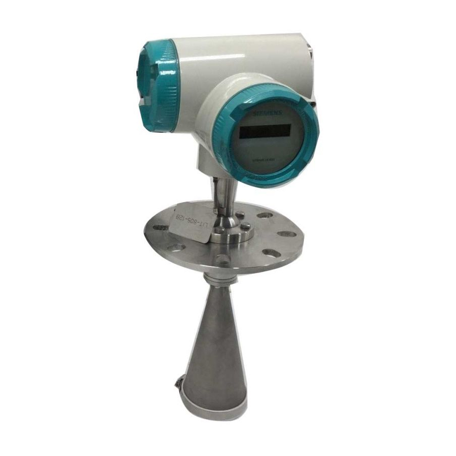
SITRANS LR 400 The SITRANS LR 400 Radar Level Instrument is designed for medium to long range level- measuring of solids and liquids in storage vessels. SITRANS LR 400 uses a high microwave frequency and operates reliably even with poorly reflecting measuring media. -
Page 8: Specifications
Specifications Note: Siemens Milltronics makes every attempt to ensure the accuracy of these specifications, but reserves the right to change them at any time. Please ensure these are the most recent specifications. Contact your representative, or check our web site at www. siemens-milltronics.com for the most up-to-date information. - Page 9 Refer to Appendix IV for charts, or obtain the reference drawing listed on the flange device tag. Flange material may be either 316/316L or 1.4571 at the discretion of Siemens Milltronics Process Instruments Inc. Actual flange material will be noted on the side of the flange.
- Page 10 19.2 kg (42.1 lbs) Easy Aimer 11.8 kg (26 lbs) Note: Please ensure these are the most recent specifications. Contact your Siemens Milltronics representative, or check our web site at www.siemens-milltronics.com for the most up-to-date information. WARNING: This product is designated as a Pressure Accessory per Directive 97/23/EC and is not intended for use as a safety device.
- Page 11 IBM-compatible RAM ≥ 64 Mbytes Hard disk ≥ 100 Mbytes RS 232-C interface VGA graphic card (≥ 640 x 480) • Software for PC/Laptop Windows 95/98/2000 or NT 4.0 SIMATIC PDM 7ML19985FH03 SITRANS LR 400 – INSTRUCTION MANUAL Page 7...
- Page 12 This product is designated as a Pressure Accessory per directive 97/23/EC and is not intended for use as a safety device. Note: Please ensure these are the most recent specifications. Contact your Siemens Milltronics representative, or check our web site at www.siemens-milltronics.com for the most up-to-date information.
-
Page 13: Dimensions
**A purging system installed between the flange and the horn antenna is an option for the SITRANS LR 400. The system provides an inlet on the flange where cooling air or cleaning fluid passes through the flange and exits the inside of the horn to clean it. The customer will supply the purging medium by manual or automatic valve system. - Page 14 SITRANS LR 400 with optional Temperature Extension 204 mm (8.0") connection cover electronics cover SI TR ANS LR intermediate flange 384 mm threaded (15.1") ring process flange* 191 mm (7.5") 238 mm horn (9.4") 74 mm (2.9") 93 mm (3.7") *Flange acc.
- Page 15 SITRANS LR 400 with optional Easy Aimer LR connection 204 mm (8.0") connection cover electronics cover intermediate 285 mm (11.2") SITRANS LR flange 412 mm (16.2") with threaded temperature extension ring Easy Aimer Flange 9.6 mm (0.38") 188.2 mm horn (7.4")
- Page 16 The user is responsible for the selection of bolting and gasket materials which will fall within the limits of the flange and its intended use and which are suitable for the service conditions. Page 12 SITRANS LR 400 – INSTRUCTION MANUAL 7ML19985FH03...
- Page 17 The user is responsible for the selection of bolting and gasket materials which will fall within the limits of the flange and its intended use and which are suitable for the service conditions. 7ML19985FH03 SITRANS LR 400 – INSTRUCTION MANUAL Page 13...
- Page 18 The user is responsible for the selection of bolting and gasket materials which will fall within the limits of the flange and its intended use and which are suitable for the service conditions. Page 14 SITRANS LR 400 – INSTRUCTION MANUAL 7ML19985FH03...
- Page 19 - 3 places, to suit M8 or 3/8" bolt holes, 120° apart, ø 7/16" (11 mm) on ø 6.2" (157 mm) clamping screw - 3 places ø 177.8 mm (7") 7ML19985FH03 SITRANS LR 400 – INSTRUCTION MANUAL Page 15...
-
Page 20: Installation
Installation Notes: • The SITRANS LR 400 is rated for Type 4X/NEMA 4X, Type 6/NEMA 6, IP 67. Follow all installation and operating instructions to meet the requirements of this type of protection. Use only approved, suitable sized hubs for watertight applications. - Page 21 (10 mm) 0.07")), as required customer mounting plate with at Long horn 9.3"( 235 mm ) least ø 4" (102 mm) central Short Horn 7.4"(188 mm) opening, as required 30° max. 7ML19985FH03 SITRANS LR 400 – INSTRUCTION MANUAL Page 17...
-
Page 22: Electrical Connection
4-20 mA, Profibus-PA, DC input circuits, 14 - 20 AWG, shielded copper wire • AC input circuit, min 14 AWG copper wire • Recommended torque on terminal clamping screws, 0.5 - 0.6 Nm Page 18 SITRANS LR 400 – INSTRUCTION MANUAL 7ML19985FH03... - Page 23 2G EEx dem [ib] IIC T6 II 2G EEx dem [ia] IIC T6 and II 2G EEx dem [ib] IIC T6, only the cover of the connection box may be unscrewed for test purposes. The cover on the power supply terminals may not be removed! 7ML19985FH03 SITRANS LR 400 – INSTRUCTION MANUAL Page 19...
-
Page 24: Start Up
Menu is displayed in the first line of the LCD. Then program the unit beginning with the Auto-Setup parameters. Auto-Setup After switching on the SITRANS LR 400, and after a successful self test, touch access the parameters. Set the Auto-Setup parameters to make the system operational: (see page 30) •... -
Page 25: Operation
Measuring Principle The SITRANS LR 400 operates according to the FMCW (Frequency Modulated Continuous Wave) method. Its antenna sends microwaves to the surface of the measuring medium, the frequency of which is modulated continuously (see Determining the Differential Frequency on page 22). - Page 26 Every reflection at a surface generates a different frequency. The reception signal therefore consists of a frequency mix from which the disturbance frequencies must be filtered. These can be caused by fixed targets such as struts inside the vessel. Page 22 SITRANS LR 400 – INSTRUCTION MANUAL 7ML19985FH03...
- Page 27 The connection of the PC/Laptops and Profibus-PA to the 4-20 mA signal cable is shown below. Connection, Profibus Schematic Diagram Class 1 Class 2 Master Master DP/PA ET200 Coupler Profibus-PA HART SITRANS LR 400 SITRANS LR 400 SITRANS LR 400 7ML19985FH03 SITRANS LR 400 – INSTRUCTION MANUAL Page 23...
-
Page 28: Operating The Sitrans Lr 400
Two lines of 16 characters each Optical control element Selecting a Parameter After a successful self-test, the SITRANS LR 400 displays the two-line multi-display. Touch to access the parameter menus. The first line of the display tells you the current parameter menu level. -
Page 29: Changing A Parameter Value
It does not save a changed setting! For an example of assigning a value from a selection list, see Operating Examples on page 28. 7ML19985FH03 SITRANS LR 400 – INSTRUCTION MANUAL Page 25... - Page 30 If you touch when the value is at the top of the representable range, SITRANS LR 400 automatically places the value at the next highest position. If 0.9 is displayed and you touch the control element , the value becomes 1.0.
-
Page 31: Disabling And Enabling Programming
We strongly recommend that a customer code be entered after all programming is completed to secure the programmed values from change. The code must be set for outdoor applications where rain drops may inadvertently activate the optical control elements. 7ML19985FH03 SITRANS LR 400 – INSTRUCTION MANUAL Page 27... -
Page 32: Operating Examples
Follow the path traced with a bold line in the diagram above for input. The other paths lead to other device functions and parameters which are not required in this example. Touch the control elements shown next to the numbered operating steps. Page 28 SITRANS LR 400 – INSTRUCTION MANUAL 7ML19985FH03... - Page 33 And end the input with the control element 4.2.2 M e a s u r.c o n d i t (“Enter” function) f i l l i n g s p e e d 7ML19985FH03 SITRANS LR 400 – INSTRUCTION MANUAL Page 29...
-
Page 34: Parameters (Hart)
The following parameters are absolutely essential for proper operation of the device. They apply to all applications and are required to make the system operational. 1. Auto-Setup Language Local (F = English) Language of the local user interface English Value Deutsch Page 30 SITRANS LR 400 – INSTRUCTION MANUAL 7ML19985FH03... - Page 35 Set the LRV as the level above the bottom of the vessel (see Functional Dimensions on page 30) in the units system selected with Function 4.1.1. It corresponds to an output current of 4 mA. 7ML19985FH03 SITRANS LR 400 – INSTRUCTION MANUAL Page 31...
-
Page 36: Additional Parameters
Display of two measured values. Values are determined in Parameter 4.5. 1 .1 (Line 1 Local) and in Parameter 4.5.1.4 (Line 2 Local). 2.2: Level (F = m) Current level of measured medium (set unit using Length Unit in Auto-Setup) Page 32 SITRANS LR 400 – INSTRUCTION MANUAL 7ML19985FH03... - Page 37 Approximate value for the previous life of the device in % (100% = approx. 10 years) This parameter outputs a calculated percentage which estimates the wear of the device due to aging. 7ML19985FH03 SITRANS LR 400 – INSTRUCTION MANUAL Page 33...
- Page 38 3.1.x: Software Diagnostic messages of the software and/or 3.1.x: Application Diagnostic messages to the application and/or 3.1.x: Parameters Display of the false parameters and/or 3.1.x: Service For service purposes only Page 34 SITRANS LR 400 – INSTRUCTION MANUAL 7ML19985FH03...
- Page 39 When this parameter is accessed and a value is entered, the device sets the defined current value that can be validated. Complete the parameter function by touching so the analog output again gives the measured value. 7ML19985FH03 SITRANS LR 400 – INSTRUCTION MANUAL Page 35...
- Page 40 S/N ratio provides a relative measure of the strength of reflection of the measuring medium in dB. Its display can be evaluated as follows: • x > 20: very good • 20 > x > 10: good • x < 10: satisfactory Page 36 SITRANS LR 400 – INSTRUCTION MANUAL 7ML19985FH03...
- Page 41 < 20: no plausible measured value 3.4.5: Sensor Temp Sensor temperature 4. Device Data 4.1: Units 4.1.1: Length Unit = Parameter 1.2 4.1.2: Volume unit (F = m bush Value bbl (liq) ImpGal 7ML19985FH03 SITRANS LR 400 – INSTRUCTION MANUAL Page 37...
- Page 42 By selecting yes or no, you specify whether the device is mounted on a stilling pipe. If you select yes, Parameter 4.2.1.3.2 is enabled so you can specify the internal diameter of the stilling pipe. Page 38 SITRANS LR 400 – INSTRUCTION MANUAL 7ML19985FH03...
- Page 43 If your measuring medium forms waves more than 1 cm in height, you should select the wavy setting. The turbulent setting is recommended for waves greater than 10 cm. 7ML19985FH03 SITRANS LR 400 – INSTRUCTION MANUAL Page 39...
- Page 44 This assigns a greater probability to measuring targets which move at this speed. Page 40 SITRANS LR 400 – INSTRUCTION MANUAL 7ML19985FH03...
- Page 45 4.2.3: Sensor Parameter Here you can view and change the sensor parameters which you have selected according to Parameter 4.2.2. Note: The factory settings for the user vessels are not editable. 7ML19985FH03 SITRANS LR 400 – INSTRUCTION MANUAL Page 41...
- Page 46 Dynamic processes in the vessel are included in the evaluation of the measuring targets. The typical filling speed can be set in Parameter 4.2.2.5. If the measured value still does not follow the level height, switching off echo motion may improve the result. Page 42 SITRANS LR 400 – INSTRUCTION MANUAL 7ML19985FH03...
- Page 47 Switch off window tracking for applications where the SITRANS LR 400 is unable to keep up to level changes or if the output remains By using SIMATIC PDM, you can display a list of all echoes in your vessel. It provides the distance between the flange and the measuring medium’s surface, as well as...
- Page 48 To calculate the volume of the measuring medium, you need the level parameters (see Parameter 4.2.4) in the units selected according to Parameter 4.1.1 and additionally a vessel characteristic (Parameter 4.2.5.7). Page 44 SITRANS LR 400 – INSTRUCTION MANUAL 7ML19985FH03...
- Page 49 4.2.5.7: Tank Characteristic (F = Calibrate/table) Determining the vessel characteristic Calibrate/table Value Calculate Select the option Calibrate/table or Calculate as required. The selection controls the display of Parameter 4.2.5.8. 7ML19985FH03 SITRANS LR 400 – INSTRUCTION MANUAL Page 45...
- Page 50 The 4.2.5.8 Calibrate/table parameter offers the following selection possibilities: 4.2.5.8.1: Calibrate Here you can enter up to 50 reference values whose levels SITRANS LR 400 measures. Enter the appropriate volume (determined by manual calibration). If you access this parameter, first the currently measured level is displayed. Accept it by pressing .
- Page 51 ≤ 1 % may occur. As well, the necessary data which you can get from the design documents of your vessel must still correspond to the real conditions. The 4.2.5.8: Calculate parameter requires the following parameters: 7ML19985FH03 SITRANS LR 400 – INSTRUCTION MANUAL Page 47...
- Page 52 D+F+W: Error Signal When D is selected, all errors are displayed. When D+F is selected, there is special handling for failsafe. When D+F+W is selected, there is special handling for warnings. Page 48 SITRANS LR 400 – INSTRUCTION MANUAL 7ML19985FH03...
- Page 53 The URV is always at 20 mA. If you set the current limit to a higher value, you can have the measured values output outside the measuring range (up to approx. 115%). 7ML19985FH03 SITRANS LR 400 – INSTRUCTION MANUAL Page 49...
- Page 54 (device error, measurement error; see Parameter 3. 1 ) to the control system. If you select the No function option, the digital output is switched off. Selection of a limit value enables Parameter 4.4.3. Page 50 SITRANS LR 400 – INSTRUCTION MANUAL 7ML19985FH03...
- Page 55 The following parameters are only enabled when the digital output supplies a limit value. 4.6.8.6: Antenna offset (see page 56) 4.6.8.7: Reference distance (see page 56) 4.4.4: Level Parameter (= Parameter 4.2.4) 4.4.4: Volume Parameter (= Parameter 4.2.5) 7ML19985FH03 SITRANS LR 400 – INSTRUCTION MANUAL Page 51...
- Page 56 Display in line 2 Level Volume Temperature Validity Value S/N ratio Amplitude Digital output Analog output 4.5.1.5: Level Parameter (= Parameter 4.2.4) 4.5.1.5: Volume Parameter (= Parameter 4.2.5) 4.5.2: Language Local (= parameter 1.1) Page 52 SITRANS LR 400 – INSTRUCTION MANUAL 7ML19985FH03...
- Page 57 4.6.4: Antenna and Flange 4.6.4.1: Flange Size (according to customer specifications) Size of the flange DN 80, 3 in DN 100, 4 in Value DN 150, 6 in Special Design 7ML19985FH03 SITRANS LR 400 – INSTRUCTION MANUAL Page 53...
- Page 58 Horn type short Special design 4.6.4.6: Flange Material (according to customer specifications) 316/316L* Value Special Design 4.6.4.7: Seal Material (according to customer specifications) Sealing material Teflon Kalrez Value Viton Special Design Page 54 SITRANS LR 400 – INSTRUCTION MANUAL 7ML19985FH03...
- Page 59 4.6.8.3: Fld Dev Rev (F = Number) Device version Value non-editable *Flange material may be either 316/316L or 1.4571 at the discretion of Siemens Milltronics Process Instruments Inc. Actual flange material will be noted on the side of the flange. 7ML19985FH03 SITRANS LR 400 –...
- Page 60 The device compares a code number which you enter here with the code defined in Parameter 5.2. If your entry matches the customer code completely, it releases the programming lock for all parameters. Any other code number locks and disables programming. Page 56 SITRANS LR 400 – INSTRUCTION MANUAL 7ML19985FH03...
- Page 61 5.3: Factory Reset (F = no) Reset all parameters to factory setting Value This parameter allows you to reset all parameters to the original factory setting as described in Parameters (HART) on page 30. 7ML19985FH03 SITRANS LR 400 – INSTRUCTION MANUAL Page 57...
-
Page 62: Parameters (Profibus-Pa)
2.2: Level Level of measured non-editable medium 2.3: Volume Volume of measured non-editable medium 2.5: Current Output Value of the analog output non-editable in mA 3: Diagnostics 3.1: Status Page 58 SITRANS LR 400 – INSTRUCTION MANUAL 7ML19985FH03... - Page 63 3.3.2: Echo Amplitude Measure of quality of reflection 3.3.3: S/N ratio Signal-to-noise ratio of the measured value in dB 3.3.4: Validity Validity of the measured value in % 3.3.5: SensorTemp Sensor temperature 4: Device data 7ML19985FH03 SITRANS LR 400 – INSTRUCTION MANUAL Page 59...
- Page 64 Silo1 (solids-pel- lets) Silo2 (solids-pow- ders) User tank1 User tank2 4.2.2.2: Surface Surface structure of the wavy smooth measured medium wavy Not displayed if a user turbulent tank is selected in [4.2.2.3]. Page 60 SITRANS LR 400 – INSTRUCTION MANUAL 7ML19985FH03...
- Page 65 These signals are then ignored during oper- ation. 4.2.3.9: Auto False Defines the end point of variable Echo Suppression the Auto False echo Distance suppression distance 4.2.4: Level param. 7ML19985FH03 SITRANS LR 400 – INSTRUCTION MANUAL Page 61...
- Page 66 4.2.5.8: HYST volume Hysteresis of the volume numerical value 0.5 m limit values 4.2.5.9: Tank charac- Determining the tank Calibrate/ Calibrate/table teristic characteristic table Calculate 4.2.5.9: Calibrate/table 4.2.5.9: Calculate Page 62 SITRANS LR 400 – INSTRUCTION MANUAL 7ML19985FH03...
- Page 67 = [4.2.5] 4.4.1.3: Volume param. 4.4.1.4: Line 2 local Display in line 2 S/N ratio Level Volume Temperature Validity S/N ratio Amplitude Digital output Analog output 4.4.1.5: Level param. = [4.2.4] 7ML19985FH03 SITRANS LR 400 – INSTRUCTION MANUAL Page 63...
- Page 68 Special design specifications 4.5.5.7: Seal material Sealing material according to Teflon customer Kalrez specifications Viton Special design 4.5.6: Tag Device identification according to up to any eight customer characters specifications Page 64 SITRANS LR 400 – INSTRUCTION MANUAL 7ML19985FH03...
- Page 69 Input of customer code to Customer code enable programmability 5.2: Customer code Determination of cus- up to 9 digit code tomer code 5.3: Factory reset Reset all parameters to factory setting 7ML19985FH03 SITRANS LR 400 – INSTRUCTION MANUAL Page 65...
-
Page 70: Troubleshooting
The SITRANS LR 400 has left the factory in a fully tested condition. Carefully selected components and compliance with prescribed quality standards guarantee the high reliability of the SITRANS LR 400. In the unlikely event of a fault, please consult the instructions in this chapter before contacting the responsible customer services. -
Page 71: Fault Messages
Liquid Store application type 4.2.2.1. SITRANS LR 400 reads instead of first echo. low or empty when Aim the SITRANS LR 400 using shims or order an material level is high Easy Aimer kit. Contact your Siemens Highly sloped surface representative for service and possible User parameter support. - Page 72 Check whether the filling speed has been correctly set (Function 4.2.2.5). d. Reduce the reflectivity (Function 4.2.2.6). e. Switch off the automatic fixed target detection (Function 4.2.3.6) if necessary. f. Switch off the multiple echo detection (Function 4.2.3.2) if necessary. Page 68 SITRANS LR 400 – INSTRUCTION MANUAL 7ML19985FH03...
-
Page 73: Maintenance
Note: The glass pressure window is available on Zone 0 / Zone 20 ATEX versions. It is located under the threaded collar of the antenna and protects the electronics from conditions within the tank. 7ML19985FH03 SITRANS LR 400 – INSTRUCTION MANUAL Page 69... -
Page 74: Certificates
Certificates The necessary certificates are enclosed separately. Page 70 SITRANS LR 400 – INSTRUCTION MANUAL 7ML19985FH03... -
Page 75: Glossary
Metal instrument formed as a cubic segment with right angles. Upper limit of the valid measuring range as a distance from the bottom inside of the vessel. Validity Measure of the certainty of the current measured value in %. 7ML19985FH03 SITRANS LR 400 – INSTRUCTION MANUAL Page 71... -
Page 76: Alphabetical Parameter List
Digital output Display Display local 4.5. 1 .2 Display parameter Display test 3.2.2 Echo amplitude 3.4.2 Echo motion 4.2.3.3 Electrical connection 4.6.3 Enter code Enter table 4.2.5.8.2 Error signal 4.3.5 Factory reset Page 72 SITRANS LR 400 – INSTRUCTION MANUAL 7ML19985FH03... - Page 77 4.2. 1 .1 Operating hours 3. 1 . 1 . 1 Operating Parameters Options Order no. 4.6.8.2 Other units 4. 1 .5 Pipe diameter (if 4.2.1.3 = yes) 4.2. 1 .3 7ML19985FH03 SITRANS LR 400 – INSTRUCTION MANUAL Page 73...
- Page 78 4.2. 1 .2 Tank volume 4.2.5.8.3 Temperature unit 4.1.4 Units Validity 3.4.4 Volume Volume damping 4.2.5.3 Volume LRV 4.2.5.2 Volume Parameters 4.2.5 Volume unit 4.1.2 Volume URV 4.2.5.1 Wear 3.1.1 Window tracking 4.2.3.4 Page 74 SITRANS LR 400 – INSTRUCTION MANUAL 7ML19985FH03...
-
Page 79: Programming Chart
4. 1 .5 Other units 4.2.1.1 Nozzle height 4.2.1.2 Tank height 4.2.1.3 Stilling pipe? 4.2.1.3 Pipe diameter (if 4.2. 1 .3 = yes) 4.2.2.1 Application type 4.2.2.2 Surface 4.2.2.3 Dead band 7ML19985FH03 SITRANS LR 400 – INSTRUCTION MANUAL Page 75... - Page 80 Level parameter 4.3.3 Volume parameter 4.3.4 Current limit 4.3.5 Error signal 4.4.1 Function DO 4.4.2 Error Level 4.4.3 Signal type DO 4.4.4 Level parameter 4.4.4 Volume parameter 4.5.1.1 Line 1 local Page 76 SITRANS LR 400 – INSTRUCTION MANUAL 7ML19985FH03...
- Page 81 Manufacturer identification 4.6.8.1 Serial no. 4.6.8.2 Order no. 4.6.8.3 Device Revision 4.6.8.4 Software revision 4.6.8.5 Hardware revision 4.6.8.6 Antenna offset 4.6.8.7 Reference distance Options 5. 1 Enter code Customer code Factory reset 7ML19985FH03 SITRANS LR 400 – INSTRUCTION MANUAL Page 77...
-
Page 82: Ambient/Operating Temperature Specification
The chart temperature also does not take into consideration heating from direct sunshine exposure. flange temperature Warning: Internal temperature must not exceed 85°C! Warranty process temperature may be void. Page 78 SITRANS LR 400 – INSTRUCTION MANUAL 7ML19985FH03... -
Page 83: Process Pressure/Temperature De-Rating
Temperature (°C) * standard process seal is rated to a max. of 200°C of continuous duty. **process seal for hazardous location is rated to a max. of 250°C of continuous duty. 7ML19985FH03 SITRANS LR 400 – INSTRUCTION MANUAL Page 79... - Page 84 • Never attempt to loosen, remove, or disassemble process connection or instrument housing with vessel contents. • Improper installation may result in loss of process pressure. Page 80 SITRANS LR 400 – INSTRUCTION MANUAL 7ML19985FH03...
-
Page 85: Hart Communications For The Sitrans Lr 400
HART Communication Foundation www.hartcomm.org The SITRANS LR 400 can be configured over the HART network using either the HART Communicator 275 by Fisher-Rosemount, or a software package. There are a number of different software packages available, and the SITRANS LR 400 should work well with any of them. - Page 86 1. Serial number 5. Fld. dev. rev. 2. Device order number 6. Software rev. 3. Actual order number 7. Hardware rev. 4. Software version 5. Hardware version 6. Antenna offset 7. Reference distance Page 82 SITRANS LR 400 – INSTRUCTION MANUAL 7ML19985FH03...
- Page 87 2. Off 3. Not used 1. Poll address Burst Option 2. Num req preams 3. Num resp preams 1. Primary variable 4. Burst mode 2. %range/current 5. Burst option 3. Process var/current 7ML19985FH03 SITRANS LR 400 – INSTRUCTION MANUAL Page 83...
- Page 88 7. Digital output 8. Analog output Supported HART Commands: The SITRANS LR 400 conforms to HART rev. 5 and supports the following: Universal Commands 0, 1, 2, 3, 6, 11, 12, 13, 14, 15, 16, 17, 18, 19 Common Practice Commands...
- Page 89 The HART commands are rarely if ever used by end users. For details on the Universal and Common Practice Commands, please contact the HART Communication Foundation. For details on the Device Specific Commands, please contact Siemens Milltronics. 7ML19985FH03 SITRANS LR 400 – INSTRUCTION MANUAL...
-
Page 90: Profibus-Pa Communications For The Sitrans Lr 400
Profibus-PA is an open industrial protocol. Full details about Profibus PA can be obtained from Profibus International at www.profibus.com The SITRANS LR 400 is a Class A, Profile Version 3.0, PA device. It supports Class 1 Master for Cyclic data exchange, and Class 2 for acyclic services: (See below for details). - Page 91 Input and output information is always requested at every bus scan and is set up as cyclic data. Configuration information is only needed periodically and is set up as acyclic data. Cyclic Data When you configure the SITRANS LR 400 on the Profibus-PA bus, there are two slots available for modules. Note: Each of the slots has to have a module defined in it.
- Page 92 1 byte 2 byte 3 byte 4 byte 5 Example 2: Floating Point Status byte1 byte 2 byte 3 byte 4 byte 5 Level Free — — — — — Place Page 88 SITRANS LR 400 – INSTRUCTION MANUAL 7ML19985FH03...
- Page 93 0x40 non-specific 0x8E high limited active critical alarm 0x8D low limited active critical alarm 0x8A high limited active advisory alarm 0x89 low limited active advisory alarm 0x84 active update event 0x80 7ML19985FH03 SITRANS LR 400 – INSTRUCTION MANUAL Page 89...
- Page 94 Import the GSD file SM_062A.GSD from the Siemens Milltronics Web site: www.siemens-milltronics.com into Step 7 software. Add the SITRANS LR 400 “rack”: click and drag the SITRANS LR 400 folder from the hardware catalog. Fill the rack with desired modules, by dragging and dropping them from the hardware catalog.
- Page 95 FMCW 21 temperature charts 78 status word 89 glossary 71 structure 3 GSD file 86 troubleshooting 66 HART Communications detailed information 81 hysteresis 44 maintenance 69 mounting location 16 operation 24 output 7ML19985FH03 SITRANS LR 400 – INSTRUCTION MANUAL Page 91...
- Page 96 Siemens Milltronics Process Instruments Inc. Siemens Milltronics Process Instruments Inc. 2002 1954Technology Drive, P .O. Box 4225 Subject to change without prior notice Peterborough, ON, Canada K9J 7B1 Rev. 3.0 Tel: (705) 745-2431 Fax: (705) 741-0466 *7ml19985FH03* Email: techpubs@siemens-milltronics.com...
Need help?
Do you have a question about the sitrans LR 400 and is the answer not in the manual?
Questions and answers