Siemens Sitrans LR400 Instruction Manual
Hide thumbs
Also See for Sitrans LR400:
- Quick start manual (114 pages) ,
- Instruction manual (109 pages) ,
- Instruction manual and users manual (106 pages)
Table of Contents
Advertisement
Quick Links
Advertisement
Table of Contents

Related Manuals for Siemens Sitrans LR400


Summary of Contents for Siemens Sitrans LR400
- Page 1 Instruction Manual May 2008 sitrans LR400...
- Page 2 The user is responsible for all changes and repairs made to the device by the user or the user’s agent. • All new components are to be provided by Siemens Milltronics Process Instruments Inc. • Restrict repair to faulty components only.
-
Page 3: Table Of Contents
Disabling and Enabling Programming ....................23 Parameter Operating Examples ......................24 Parameters (HART) ......................26 Vessel Functional Dimensions ......................27 Required Parameters ..........................27 Additional Parameters .........................29 Parameters (PROFIBUS PA) ....................68 Troubleshooting .........................81 Classification of Faults .........................81 Self-test ..............................81 7ML19985FH06 SITRANS LR400 (7ML5421) – INSTRUCTION MANUAL... - Page 4 HART Device Description (DD) ....................93 SIMATIC Process Device Manager (PDM) ................93 HART Communicator 275/375: ....................94 Appendix V .........................97 PROFIBUS PA Communications for SITRANS LR400 ..............97 Device Description ........................97 The GSD file ..........................97 Bus address (Device Address) ....................97 Bus Termination ...........................98 Power Demands ..........................98...
-
Page 5: General Information
Please ensure that any safety-related information is confirmed with a qualified Siemens Milltronics representative. WARNINGS: • Changes or modifications not expressly approved by Siemens Milltronics could void the user’s authority to operate the equipment. • This equipment is intended to be used only in fully enclosed metal and concrete containers. -
Page 6: Abbreviations And Identifications
• Installation shall only be performed by qualified personnel and in accordance with local governing regulations. • The SITRANS LR400 is to be used only in the manner outlined in this manual, otherwise protection provided by equipment may be impaired. -
Page 7: Sitrans Lr400
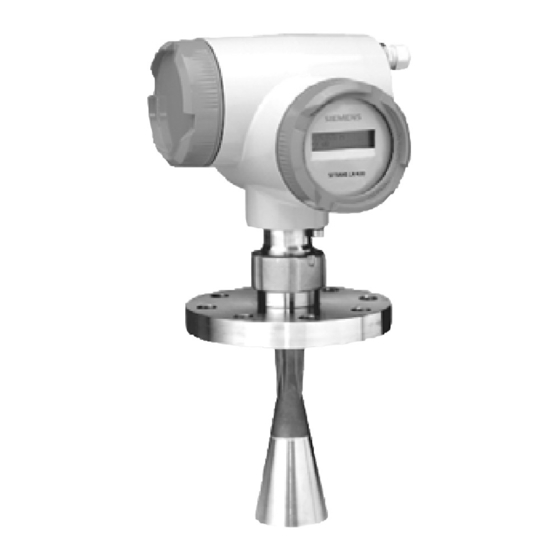
SITRANS LR400 SITRANS LR400 is a long-range FMCW radar level transmitter. It is suitable for use in liquids and solids, for low dielectric liquids, and high pressure applications or applications with extreme dust. This version also incorporates a purging option for sticky solids applications. -
Page 8: System Implementation
SITRANS LR400 SITRANS LR400 Programming SITRANS LR400 carries out its level measurement function according to the set of built-in parameter tables. You can make parameter changes via the hand programmer, a PC running SIMATIC PDM or a HART handheld communicator. -
Page 9: Specifications
Specifications Siemens Milltronics makes every attempt to ensure the accuracy of these Note: specifications, but reserves the right to change them at any time. SITRANS LR400 Power Power Supply ± • 100 to 230 V AC, 15%, 50/60 Hz, 6 W •... - Page 10 Programmer (infrared keypad) Siemens Milltronics Infrared IS (Intrinsically Safe) hand programmer for hazardous and all other locations (battery is non-replaceable) • approval: ATEX II 1 G, EEx ia IIC T4, certificate SIRA 01ATEX2147 CSA and FM Class I, Div.
- Page 11 Use only approved, suitable sized hubs for watertight applications. See Process/Ambient de-rating curves in Appendix III. -20 °C (-4 °F) temperature rating available on SITRANS LR400 with ATEX rating. 7ML19985FH06 SITRANS LR400 (7ML5421) – INSTRUCTION MANUAL...
- Page 12 - Lloyd’s Register of Shipping, Categories ENV1, ENV2, ENV3, and ENV5 - ABS This product is designated as a Pressure Accessory per WARNING: directive 97/23/EC and is not intended for use as a safety device. Page 8 SITRANS LR400 (7ML5421) – INSTRUCTION MANUAL 7ML19985FH06...
-
Page 13: Dimensions
Dimensions SITRANS LR400 (7ML5421 version) (without Temperature Extension) 204 mm earth (8.0") terminal connection cover electronics cover 257 mm SITRANS LR 4 00 intermediate (10.1")** flange threaded ring process flange* 191 mm (7.5") 238 mm horn (9.4") 74 mm (2.9") 93 mm (3.7") - Page 14 SITRANS LR400 (7ML5421 version) with optional Temperature Extension 204 mm (8.0") connection cover electronics cover SITRANS L R 400 intermediate flange 384 mm (15.1") threaded ring process flange* 191 mm (7.5") horn 238 mm (9.4") 74 mm (2.9") 93 mm (3.7")
- Page 15 The user is responsible for the selection of bolting and WARNING: gasket materials which will fall within the limits of the flange and its intended use and which are suitable for the service conditions. 7ML19985FH06 SITRANS LR400 (7ML5421) – INSTRUCTION MANUAL Page 11...
- Page 16 The user is responsible for the selection of bolting and WARNING: gasket materials which will fall within the limits of the flange and its intended use and which are suitable for the service conditions. Page 12 SITRANS LR400 (7ML5421) – INSTRUCTION MANUAL 7ML19985FH06...
-
Page 17: Air Purging System (Optional)
• Some dust particles are highly abrasive and can be drawn into the inside of the horn during purge cleaning, damaging the internal PTFE emitter of the antenna. A replacement kit is available from your local Siemens Milltronics representative. • It is the customer’s responsibility to ensure that any vacuum or pressure in the measured vessel is maintained, considering the hole that passes through the process connection and SITRANS LR400 antenna system. - Page 18 The user is responsible for the selection of bolting and WARNING: gasket materials which will fall within the limits of the flange and its intended use and which are suitable for the service conditions. Page 14 SITRANS LR400 (7ML5421) – INSTRUCTION MANUAL 7ML19985FH06...
-
Page 19: Installation
Installation Notes: • SITRANS LR400 is rated for Type 4X/NEMA 4X, Type 6/NEMA 6, IP67. Follow all installation and operating instructions to meet the requirements of this type of protection. Use only approved, suitable sized hubs for watertight applications. •... -
Page 20: Beam Width
Above flange size SITRANS LR 400 DN 150/6", the antenna need not project beyond the nozzle unless the radiation cone (the extension of the antenna’s angle) touches the nozzle wall. 10 mm Page 16 SITRANS LR400 (7ML5421) – INSTRUCTION MANUAL 7ML19985FH06... -
Page 21: Electrical Connection
4-20 mA, PROFIBUS PA, DC input circuits, 14 - 20 AWG, shielded copper wire • AC input circuit, min 14 AWG copper wire • Recommended torque on terminal clamping screws, 0.5 - 0.6 Nm. 7ML19985FH06 SITRANS LR400 (7ML5421) – INSTRUCTION MANUAL Page 17... - Page 22 2G EEx dem [ib] IIC T6 II 2G EEx dem [ia] IIC T6 and II 2G EEx dem [ib] IIC T6 (7ML5421 version), only the cover of the connection box may be unscrewed for test purposes. The cover on the power supply terminals may not be removed! Page 18 SITRANS LR400 (7ML5421) – INSTRUCTION MANUAL 7ML19985FH06...
-
Page 23: Start Up
LCD line. Then program the unit beginning with the Auto-Setup parameters. Auto-Setup After switching on the SITRANS LR400, and after a successful self test, press LEFT access the parameters. Set the Auto-Setup parameters to make the system operational: (see page 27) •... -
Page 24: Operation
Operating SITRANS LR400 Use the arrow keys at the bottom of the hand programmer to program SITRANS LR400. The two-line LCD displays the parameters. You can alter the setting or change to other parameters using the arrows on the hand programmer (see page 22 for information on navigating the menus using the arrow keys). -
Page 25: Selecting A Parameter
Selecting a Parameter After a successful self-test, SITRANS LR400 displays the two-line multi-display. Press LEFT ARROW to access the parameter menus. The first line of the display shows the current parameter menu level. The second line shows one of the parameters you can access in the current parameter group. -
Page 26: Changing A Parameter Value
If you press UP when the value is at the top of the representable range, SITRANS LR400 automatically places the value at the next highest position. If 0.9 is displayed and you press UP , the value becomes 1.0. So, 9 becomes 10, 90 or 99 become 100 (depending on whether you have set the input position to the second or first 9), etc. -
Page 27: Disabling And Enabling Programming
If Customer Code (Parameter 5.2) is 0, programming of parameters is always Note: enabled. We strongly recommend that a customer code be entered after all programming is completed to secure the programmed values from change. 7ML19985FH06 SITRANS LR400 (7ML5421) – INSTRUCTION MANUAL Page 23... -
Page 28: Parameter Operating Examples
2. Operat. param. 4.3 Analog output 4.3.1 Error level 4. Device data 1 Error level D: Error signal 3 Analog output 4.3 Analog output 4.3.2 AO select 2 AO select 1 Level Page 24 SITRANS LR400 (7ML5421) – INSTRUCTION MANUAL 7ML19985FH06... - Page 29 End the input with RIGHT (ENTER). 4 . 2 . 2 . M e a s u r. c o n d F i l l i n g s p e e d 7ML19985FH06 SITRANS LR400 (7ML5421) – INSTRUCTION MANUAL Page 25...
-
Page 30: Parameters (Hart)
: Failsafe Level 4.2.2. : Failsafe Timer 4.2.2. : Failsafe Timer 4.2.2. : Range Extension 4.2.2. : Range Extension Default values are indicated as "F=" following the parameter number and name. Page 26 SITRANS LR400 (7ML5421) – INSTRUCTION MANUAL 7ML19985FH06... -
Page 31: Vessel Functional Dimensions
1.1 Language Local (F = English) Selects the language to be used on the LCD English Value Deutsch 1.2 Length Unit (F = m) Specifies measurement units used for dimensional values Value 7ML19985FH06 SITRANS LR400 (7ML5421) – INSTRUCTION MANUAL Page 27... - Page 32 Sets the damping of the level value in seconds Value numerical value The damping acts on the analog output, the limit value monitor and the local display. For damping of the sensor signal, set Parameter 4.2.3.1. Page 28 SITRANS LR400 (7ML5421) – INSTRUCTION MANUAL 7ML19985FH06...
-
Page 33: Additional Parameters
2.2 Level (F = m) Current level of material (set unit using Length Unit in Auto-Setup) 2.3 Volume (F = m Volume of material (set unit using Parameter 4.1.2 [Volume Unit]) 7ML19985FH06 SITRANS LR400 (7ML5421) – INSTRUCTION MANUAL Page 29... - Page 34 This parameter outputs a calculated percentage which estimates the wear of the device due to aging. 3.1.1. 5 Hours > 85 °C Total time the maximum permissible internal temperature (85 °C) was exceeded, in hours Page 30 SITRANS LR400 (7ML5421) – INSTRUCTION MANUAL 7ML19985FH06...
- Page 35 Diagnostic messages regarding the application and/or 3.1.x Parameters Display any of non-compatible programmed parameters and/or 3.1.x Service MC For factory service purposes only 3.1.x Service DSP For factory service purposes only 7ML19985FH06 SITRANS LR400 (7ML5421) – INSTRUCTION MANUAL Page 31...
- Page 36 Complete the parameter entry by pressing LEFT so the analog output again gives the measured value. 3.3.2 Simulate DO (F = End) Simulation of the digital output signal Relay on Value Relay off Page 32 SITRANS LR400 (7ML5421) – INSTRUCTION MANUAL 7ML19985FH06...
- Page 37 Its display can be evaluated as follows: • x > 1: very good • 1 > x > 0.5: good • 0.5 > x > 0.05: satisfactory • x < 0.05: uncertain 7ML19985FH06 SITRANS LR400 (7ML5421) – INSTRUCTION MANUAL Page 33...
- Page 38 Internal electronics sensor temperature 4. Device Data 4.1 Units 4.1.1 Length Unit = Parameter 1.2 4.1.2 Volume unit (F = m Specifies volume units used for dimensional values bush Value bbl (liq) ImpGal Page 34 SITRANS LR400 (7ML5421) – INSTRUCTION MANUAL 7ML19985FH06...
- Page 39 (see Parameters 4.3 and 4.4). 4.2.1 Tank Geometry 4.2.1.1 Nozzle Height = Parameter 1.3 4.2.1.2 Tank Height = Parameter 1.4 4.2.1.3 Stilling Pipe? (F = no) [7ML5421 version] Stilling pipe available? Value 7ML19985FH06 SITRANS LR400 (7ML5421) – INSTRUCTION MANUAL Page 35...
- Page 40 • 4.2.3.3 (Echo Motion) • 4.2.3.4 (Window Tracking) • 4.2.3.5 (Tank Empty Detect) The parameters that remain under 4.2.2.x will be renumbered. See page 26 for more information on parameter renumbering. Page 36 SITRANS LR400 (7ML5421) – INSTRUCTION MANUAL 7ML19985FH06...
- Page 41 K = correction factor, p = pressure inside the vessel in bar, Tgas = gas temperature in °C, ε = dielectric of the overlying gas, e.g. ερ = 1.00059 r, Gas , air Enter the correction factor as a dimensionless value. 7ML19985FH06 SITRANS LR400 (7ML5421) – INSTRUCTION MANUAL Page 37...
- Page 42 The failsafe timer begins when there is a loss of echo condition. This loss of echo condition will occur when there is no signal available above the Auto False-Echo Suppression threshold as defined in Parameter 4.2.3.9. Page 38 SITRANS LR400 (7ML5421) – INSTRUCTION MANUAL 7ML19985FH06...
- Page 43 Evaluate multiple echoes. The multiple echo evaluation suppresses multiple reflections by assigning them a lower probability than the measuring signal. Value This parameter is not displayed when a user vessel is selected in Parameter 4.2.2.1. 7ML19985FH06 SITRANS LR400 (7ML5421) – INSTRUCTION MANUAL Page 39...
- Page 44 Switch off window tracking for applications where SITRANS LR400 is unable to keep up to level changes. By using SIMATIC PDM, you can display a list of all echoes in your vessel. It provides the distance between the flange and the measuring medium’s surface, as well as the distances of fixed targets.
- Page 45 If all signals fall below this defined threshold, then the failsafe timer is initiated. 4.2.3.9 Auto False-Echo Suppression Distance (F = 2/3 tank height) Defines the end point of the auto false echo suppression distance. Value variable to maximum range 7ML19985FH06 SITRANS LR400 (7ML5421) – INSTRUCTION MANUAL Page 41...
- Page 46 Defines (in percent) how high the TVT (Time Varying Threshold) curve is placed above the echo profile, relative to the largest echo. When SITRANS LR400 is located in the center of the vessel, lower the hover level to prevent multiple echo detections.
- Page 47 Set the hysteresis of the limit values in the units system selected according to Parameter 4. 1 .1 (see diagram below). Limit value alarm measuring variable measuring variable upper limit value hysteresis hysteresis limit value lower limit alarm value limit value alarm time time 7ML19985FH06 SITRANS LR400 (7ML5421) – INSTRUCTION MANUAL Page 43...
- Page 48 4.2.5.6 HYST Volume (F = 0.5 m Hysteresis of the volume limit values Value numerical value 4.2.5.7 Tank Characteristic (F = Calculate) Determining the vessel characteristic Calibrate/table Value Calculate Page 44 SITRANS LR400 (7ML5421) – INSTRUCTION MANUAL 7ML19985FH06...
- Page 49 The 4.2.5.8 Calibrate/table parameter offers the following selection possibilities: 4.2.5.8.1 Calibrate Here you can enter up to 50 reference values whose levels SITRANS LR400 measures. Enter the appropriate volume (determined by manual calibration). If you access this parameter, first the currently measured level is displayed. Accept it...
- Page 50 ≤ 1 % may occur. As well, the necessary data which you can get from the design documents of your vessel must still correspond to the real conditions. The 4.2.5.8: Calculate parameter requires the following parameters: Page 46 SITRANS LR400 (7ML5421) – INSTRUCTION MANUAL 7ML19985FH06...
- Page 51 4.2.6.2 Mass LRV (for qualified personnel only) 4.2.6.3 Mass Damping (for qualified personnel only) 4.2.6.4 MinLim Mass (for qualified personnel only) 4.2.6.5 MaxLim Mass (for qualified personnel only) 4.2.6.6 HYST Mass (for qualified personnel only) 7ML19985FH06 SITRANS LR400 (7ML5421) – INSTRUCTION MANUAL Page 47...
- Page 52 4.3: Analog Output 4.3.1 Error Level (F = D: Error Signal) Level for the error signal to alarm in Analog or Digital output D: Error Signal Value D+F: Error Signal D+F+W: Error Signal Page 48 SITRANS LR400 (7ML5421) – INSTRUCTION MANUAL 7ML19985FH06...
- Page 53 20 - 22.5 mA Here you can set the upper current limit of the output signal in steps of 0.1 mA. Current limiting current 22.5 mA setting range 20.0 mA measured value 7ML19985FH06 SITRANS LR400 (7ML5421) – INSTRUCTION MANUAL Page 49...
- Page 54 No function Selection of a limit value enables Parameter 4.4.4. If you select Alarm or No Note: function in this parameter, Parameter 4.4.4 will not be visible. Page 50 SITRANS LR400 (7ML5421) – INSTRUCTION MANUAL 7ML19985FH06...
- Page 55 The value of 4.5.1.3 is determined by the selection (Level, Volume or Mass) in Note: Parameter 4.5.1.1 (Line 1 Local). 4.5.1.2 Display Local (F = Eng Unit) Line 1 of local display Eng unit Value Bar graph 7ML19985FH06 SITRANS LR400 (7ML5421) – INSTRUCTION MANUAL Page 51...
- Page 56 If 4.5.1.4 (Line 2 Local) = Mass 4.5.1.5 Mass Parameter (= Parameter 4.2.6) 4.5.2 Language Local (= Parameter 1.1) 4.5.3 LCD Backlight (F = off) Background illumination of the LCD Value Page 52 SITRANS LR400 (7ML5421) – INSTRUCTION MANUAL 7ML19985FH06...
- Page 57 4.6.4.2 Flange Type (according to customer specifications) Type of flange ANSI Value Universal solid Universal liquid Easy Aimer Special design 4.6.4.3 Pressure Range (according to customer specifications) Pressure range of the process connection Value non-editable 7ML19985FH06 SITRANS LR400 (7ML5421) – INSTRUCTION MANUAL Page 53...
- Page 58 4.6.4.7 Seal Material (according to customer specifications) Sealing material PTFE FFKM Value Special design PTFE: Polytetrafluoroethylene; FFKM: Perfluoroelastomer; FKM: Fluoroelas- tomer 4.6.5 Tag (according to customer specifications) Device identification Value up to any eight characters Page 54 SITRANS LR400 (7ML5421) – INSTRUCTION MANUAL 7ML19985FH06...
- Page 59 Distance from sensor to flange The antenna offset defines the propagation time of the measuring signal between the sensor and the flange as a distance. It is preset at the factory and cannot be changed. 7ML19985FH06 SITRANS LR400 (7ML5421) – INSTRUCTION MANUAL Page 55...
- Page 60 5.3 Factory Reset (F = no) Reset all parameters to factory setting Value This parameter allows you to reset all parameters to the original factory setting as described in Parameters (HART) beginning on page 26. Page 56 SITRANS LR400 (7ML5421) – INSTRUCTION MANUAL 7ML19985FH06...
- Page 61 To modify the value via SIMATIC PDM: a. Modify limit values as required. b. See 6.1.5 Maintenance Alert Activation to set Alert Activation options. Data for this parameter must be entered in seconds on the device. 7ML19985FH06 SITRANS LR400 (7ML5421) – INSTRUCTION MANUAL Page 57...
- Page 62 Enter the desired value (or click Snooze to add a year to the current value), then click on Write to accept the change. c. Click on Read to view the effect of the modification. Data for this parameter must be entered in seconds on the device. Page 58 SITRANS LR400 (7ML5421) – INSTRUCTION MANUAL 7ML19985FH06...
- Page 63 Open the menu View - Device Status (PROFIBUS PA) or View – Status (HART), and click on the Maintenance tab. b. In the Device Lifetime window click on Acknowledge Warnings. DO NOTHING Options (read only) ACKNOWLEDGE 7ML19985FH06 SITRANS LR400 (7ML5421) – INSTRUCTION MANUAL Page 59...
- Page 64 To modify the value via SIMATIC PDM: a. Modify limit values as required. b. Enable 6.2.5 Maintenance Alert Activation to set the Alert Activation options. Data for this parameter must be entered in seconds on the device. Page 60 SITRANS LR400 (7ML5421) – INSTRUCTION MANUAL 7ML19985FH06...
- Page 65 Click on Read to view the effect of the modification. 6.2.7 Units Allows you to set desired units using SIMATIC PDM. SECONDS HOURS Options DAYS YEARS Data for this parameter must be entered in seconds on the device. 7ML19985FH06 SITRANS LR400 (7ML5421) – INSTRUCTION MANUAL Page 61...
- Page 66 Options (read only) ACKNOWLEDGE 6.3 Service Interval Allows for scheduling of service inspections. To access these parameters via SIMATIC PDM, open the menu Device – Maintenance and click on the Service Interval tab. Page 62 SITRANS LR400 (7ML5421) – INSTRUCTION MANUAL 7ML19985FH06...
- Page 67 6.3.5 Total Service Interval Set time between scheduled service inspections Range: 0 to 20 years Values Default: 1.0 year Data for this parameter must be entered in seconds on the device. 7ML19985FH06 SITRANS LR400 (7ML5421) – INSTRUCTION MANUAL Page 63...
- Page 68 Open the menu View - Device Status (PROFIBUS PA) or View – Status (HART), and click on the Maintenance tab. b. In the Service Interval window, click on Acknowledge Warnings. DO NOTHING Options (read only) ACKNOWLEDGE Page 64 SITRANS LR400 (7ML5421) – INSTRUCTION MANUAL 7ML19985FH06...
- Page 69 Timer On, Maintenance Required and ON, LIMITS 1 + 2 Demanded Enabled ON, LIMIT 2 Timer On, Maintenance Demanded Enabled Data for this parameter must be entered in seconds on the device. 7ML19985FH06 SITRANS LR400 (7ML5421) – INSTRUCTION MANUAL Page 65...
- Page 70 ACK MAINT DEM Maintenance Demanded Acknowledged In SIMATIC PDM, open the menu View - Device Status (PROFIBUS PA) or View – Status (HART), click on the Maintenance tab and check the Calibration Interval window. Page 66 SITRANS LR400 (7ML5421) – INSTRUCTION MANUAL 7ML19985FH06...
- Page 71 Open the menu View - Device Status (PROFIBUS PA) or View – Status (HART), and click on the Maintenance tab. b. In the Calibration Interval window, click on Acknowledge Warnings. DO NOTHING Options (read only) ACKNOWLEDGE 7ML19985FH06 SITRANS LR400 (7ML5421) – INSTRUCTION MANUAL Page 67...
-
Page 72: Parameters (Profibus Pa)
2.2: Level Level of material Read-only 2.3: Volume Volume of material Read-only 2.4: Mass For qualified personnel only 3: Diagnostics 3.1: Status 3. 1 .1: Wear Page 68 SITRANS LR400 (7ML5421) – INSTRUCTION MANUAL 7ML19985FH06... - Page 73 3.2: Device test 3.2.1: Self-test Check device state Read-only 3.2.2: Display test Visual check of LCD Read-only 3.3: Simulation 3.3.1: Error Simula- For factory service purposes only tion for Micro High Word 7ML19985FH06 SITRANS LR400 (7ML5421) – INSTRUCTION MANUAL Page 69...
- Page 74 = [1.2] 4. 1 .2: Volume unit Specifies volume units used for dimensional val- bush bbl (liq) ImpGal 4. 1 .3: Mass unit Specifies mass units used for dimensional val- LTon STon Page 70 SITRANS LR400 (7ML5421) – INSTRUCTION MANUAL 7ML19985FH06...
- Page 75 4.2.2.5: Filling speed Typical speed of change 200 mm/min numerical value of the level Not displayed if a user tank is selected in [4.2.2.1]. 7ML19985FH06 SITRANS LR400 (7ML5421) – INSTRUCTION MANUAL Page 71...
- Page 76 These signals are then ignored during oper- ation. 4.2.3.9: Auto False Defines the end point of 2/3 tank variable Echo suppression the Auto False-Echo height distance Suppression distance Page 72 SITRANS LR400 (7ML5421) – INSTRUCTION MANUAL 7ML19985FH06...
- Page 77 Lower limit value of the numerical value volume 4.2.5.6: MaxLim vol- Upper limit value of the numerical value 20 m volume 4.2.5.7: MaxWarn Limit before reaching 20 m numerical value volume upper limit value 7ML19985FH06 SITRANS LR400 (7ML5421) – INSTRUCTION MANUAL Page 73...
- Page 78 4.2.6.5: MinLim mass For qualified personnel only 4.2.6.6: MaxLim mass For qualified personnel only 4.2.6.7: MaxWarn For qualified personnel only Mass 4.2.6.8: HYST Mass For qualified personnel only 4.2.6.9: Tank Charac- For qualified personnel only Page 74 SITRANS LR400 (7ML5421) – INSTRUCTION MANUAL 7ML19985FH06...
- Page 79 4.4.1: Multi display 4.4.1.1: Line 1 local Choice of measured Level Level value in line 1 Volume Mass 4.4.1.2: Display local Method of display in line Eng unit Eng unit Bargraph 7ML19985FH06 SITRANS LR400 (7ML5421) – INSTRUCTION MANUAL Page 75...
- Page 80 4.5.2: Flange temp. Temperature range of the according to Read-only flange in °C customer specifica- tions 4.5.3: Electrical con- according to Read-only nection customer specifica- tions 4.5.4: Antenna and flange Page 76 SITRANS LR400 (7ML5421) – INSTRUCTION MANUAL 7ML19985FH06...
- Page 81 4.5.5: Tag Device identification according to up to any eight customer characters specifica- tions 4.5.6: Descriptor Measuring point descrip- according to up to any 16 char- tion customer acters specifica- tions 7ML19985FH06 SITRANS LR400 (7ML5421) – INSTRUCTION MANUAL Page 77...
- Page 82 Operating Time only 6.1.2: Restlife For qualified personnel Read-only only 6. 1 .3: Maintenance For qualified personnel Read/Write only Required Limit 6. 1 .4: Maintenance For qualified personnel Read/Write Demanded Limit only Page 78 SITRANS LR400 (7ML5421) – INSTRUCTION MANUAL 7ML19985FH06...
- Page 83 6.3: Remaining Service Interval 6.3.1: Time Elapsed For qualified personnel Read-only Since Last Service only 6.3.2: Maintenance For qualified personnel Read/Write Required Limit only 6.3.3: Maintenance For qualified personnel Read/Write Demanded Limit only 7ML19985FH06 SITRANS LR400 (7ML5421) – INSTRUCTION MANUAL Page 79...
- Page 84 For qualified personnel Read/Write Status only 6.4.8: Acknowledge For qualified personnel Read-only Status only 6.4.9: Acknowledge For qualified personnel Read-only only Data for these parameters must be entered in seconds on the device. Page 80 SITRANS LR400 (7ML5421) – INSTRUCTION MANUAL 7ML19985FH06...
-
Page 85: Troubleshooting
LR400. Please review the instructions below for troubleshooting assistance before contacting Siemens Milltronics. Classification of Faults Faults occurring in SITRANS LR400 can be classified in the following groups: • faults caused by ambient influences: over- and under-temperature, moisture, contamination by the material and other substances, mains faults, vibration •... -
Page 86: Fault Messages
Liquid Store application type 4.2.2.1. low or empty when instead of first echo. material level is high Highly sloped surface Aim SITRANS LR400 using Easy Aimer ball. Damping too high Decrease 4.2.3.1 Sensor Damping SITRANS LR400 Decrease Level Damping Window Tracking reading is too slow. - Page 87 Calibration interval has exceeded the Calibration ’Maint Required Limit’ (Calibration Perform calibration. Schedule Limit1 Schedule Limit 1). Calibration interval has exceeded the Calibration ’Maint Demanded Limit’ (Calibration Perform calibration. Schedule Limit2 Schedule Limit 2). 7ML19985FH06 SITRANS LR400 (7ML5421) – INSTRUCTION MANUAL Page 83...
-
Page 88: Unit Repair And Excluded Liability
Please note the following: • The user is responsible for all changes and repairs made to the device. • All new components must be provided by Siemens Milltronics Process Instruments Inc. • Restrict repair to faulty components only •... - Page 89 Notes: 7ML19985FH06 SITRANS LR400 (7ML5421) – INSTRUCTION MANUAL Page 85...
-
Page 90: Antenna Maintenance
If the antenna is contaminated, any built-up material can be removed using air or soft brushes. Be careful not to damage the PTFE emitter cone inside the antenna. An optional purge kit is available from Siemens Milltronics if required. Contact your local Siemens Millltronics representative for more details. -
Page 91: Hazardous Installation
Hazardous Installation The necessary certificates are enclosed separately. Please refer to the SITRANS LR400 Certificate manual 7ML19985FP82. 7ML19985FH06 SITRANS LR400 (7ML5421) – INSTRUCTION MANUAL Page 87... -
Page 92: Ambient/Operating Temperature Specification
Warning: Internal temperature must not exceed 85 °C (185 °F)! process temperature Warranty may be void. Page 88 SITRANS LR400 (7ML5421) – INSTRUCTION MANUAL 7ML19985FH06... -
Page 93: Process Pressure/Temperature De-Rating
* standard process seal is rated to a max. of 200 °C of continuous duty. **process seal for hazardous location is rated to a max. of 250 °C of continuous duty. 7ML19985FH06 SITRANS LR400 (7ML5421) – INSTRUCTION MANUAL Page 89... - Page 94 • Never attempt to loosen, remove, or disassemble process connection or instrument housing with vessel contents. • Improper installation may result in loss of process pressure. Page 90 SITRANS LR400 (7ML5421) – INSTRUCTION MANUAL 7ML19985FH06...
-
Page 95: Measuring Principle
Appendix III Measuring Principle SITRANS LR400 operates according to the FMCW (Frequency Modulated Continuous Wave) method. Its antenna sends microwaves to the surface of the material. The wave frequency is modulated continuously (see Determining the Differential Frequency on 92). A receiver registers the reflection at the surface of the measuring medium and links it with the simultaneously radiated signal. - Page 96 Every reflection at a surface generates a different frequency. The reception signal therefore consists of a frequency mix from which the disturbance frequencies must be filtered. These can be caused by fixed targets like struts inside the vessel. Page 92 SITRANS LR400 (7ML5421) – INSTRUCTION MANUAL 7ML19985FH06...
-
Page 97: Hart Communications For Sitrans Lr400
SITRANS LR400 should work well with any of the different software packages available. HART Device Description (DD) The SITRANS LR400 cannot be set up using a Generic DD. To configure a HART device, the configurator must have the HART Device Description for the SITRANS LR400. All HART DDs are collected by the HART Communication Foundation (HCF) and are placed in the HCF library. -
Page 98: Hart Communicator 275/375
1. Serial number 5. Fld. dev. rev. 2. Device order number 6. Software rev. 3. Actual order number 7. Hardware rev. 4. Software version 5. Hardware version 6. Antenna offset 7. Reference distance Page 94 SITRANS LR400 (7ML5421) – INSTRUCTION MANUAL 7ML19985FH06... - Page 99 3. Mass damping 4. Clear table 4. MinLim Mass 5. MaxLim Mass calculate 6. HYST Mass 1. Tank design 7. Tank characteristic 2. Bottom design 8. Calibrate/table 3. Tank volume or Calculate 7ML19985FH06 SITRANS LR400 (7ML5421) – INSTRUCTION MANUAL Page 95...
- Page 100 1. Eng unit 2. % 3. Bar graphic Line 2 Local 1. Level 2. Volume 3. Mass 4. Temperature 5. Validity 6. S/N ratio 7. Amplitude 8. Digital output 9. Analog output Page 96 SITRANS LR400 (7ML5421) – INSTRUCTION MANUAL 7ML19985FH06...
-
Page 101: Profibus Pa Communications For Sitrans Lr400
PROFIBUS PA is an open industrial protocol. Full details about PROFIBUS PA can be obtained from PROFIBUS International at www.profibus.com SITRANS LR400 is a Profile 3.0, Class A, PA device. It supports Class 1 Master for Cyclic data exchange, and Class 2 for acyclic services: (See below for details). -
Page 102: Bus Termination
Configuration information is only needed periodically and is set up as acyclic data. Cyclic Data When you configure SITRANS LR400 on the PROFIBUS PA bus, there are two slots available for modules. Each of the slots has to have a module defined in it. - Page 103 Floating Point Status byte1 byte 2 byte 3 byte 4 byte 5 Level Free — — — — — Place Mass byte 6 byte 7 byte 8 byte 9 byte 10 7ML19985FH06 SITRANS LR400 (7ML5421) – INSTRUCTION MANUAL Page 99...
-
Page 104: Status Word
0x0F constant device failure 0x0C device failure 0x13 constant sensor failure 0x12 high limited sensor failure 0x11 low limited sensor failure 0x10 sensor failure 0x07 constant configuration error Page 100 SITRANS LR400 (7ML5421) – INSTRUCTION MANUAL 7ML19985FH06... -
Page 105: Extended Diagnostics
0 = not set 1 = set Acyclic Data SITRANS LR400 supports up to three simultaneous connections by a class 2 Master (C2 connection). It does not support Master Class 1 (C1 connection). Configuration Example: To configure and use PROFIBUS PA with an S7-300/400 PLC Import the GSD file SM_062A.GSD. -
Page 106: Appendix Vi: Firmware Revision History
"Advanced Echo Processing" • Added support for new parameters (hover level and window trigger) • Changes to the echo profile graph in SIMATIC PDM to correspond to other Siemens Milltronics products. • Cleanup/addition of default values and help messages •... - Page 107 Fixed issue regarding Volume/Mass table entry deletion density units • Fixed issue using g/cm • PROFIBUS PA, quality 0x40 and diagnosis octet 1, 3.14 May 17, 2008 bit 5 set only after LOE expired 7ML19985FH06 SITRANS LR400 (7ML5421) – INSTRUCTION MANUAL Page 103...
-
Page 108: Glossary
(DK): the ability of a dielectric to store electrical potential energy under the influence of an electric field. Also known as Relative Permittivity. An increase in the Many conductive liquids/electrolytes exhibit dielectric properties; the relative dielectric constant of water is 80. Page 104 SITRANS LR400 (7ML5421) – INSTRUCTION MANUAL 7ML19985FH06... - Page 109 7ML19985FH06 SITRANS LR400 (7ML5421) – INSTRUCTION MANUAL Page 105...
- Page 110 URV: Upper limit of the valid measuring range as a distance from the bottom inside of the vessel validity: measure of the certainty of the current measured value in %. waveguide antenna: a hollow, metallic tube that transmits a microwave signal to the product target. Page 106 SITRANS LR400 (7ML5421) – INSTRUCTION MANUAL 7ML19985FH06...
-
Page 111: Index
GSD file ............97 status word ..........100 structure ............3 hand programmer ......19 HART Communications troubleshooting ..........81 detailed information ......93 hysteresis ............ 43 maintenance ..........86 mounting location ..........15 operation ............. 20 7ML19985FH06 SITRANS LR400 (7ML5421) – INSTRUCTION MANUAL Page 107... - Page 112 Siemens Milltronics Process Instruments Inc. Siemens Milltronics Process Instruments Inc. 2008 1954Technology Drive, P .O. Box 4225 Subject to change without prior notice Peterborough, ON, Canada K9J 7B1 7ML5421 Tel: (705) 745-2431 Fax: (705) 741-0466 *7ml19985FH06* Rev. 6.4 Email: techpubs.smpi@siemens.com...
Need help?
Do you have a question about the Sitrans LR400 and is the answer not in the manual?
Questions and answers