Advertisement
Quick Links
Download this manual
See also:
User Manual
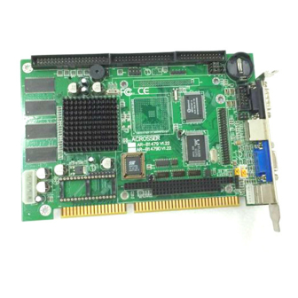
AR-B1479 Manual
Version 1.2
1. SETTING UP THE SYSTEM
1.1 PACKING LIST
!
The quick setup manual
!
1 AR-B1479 CPU board
!
1 Hard disk drive adapter cable for 3.5" HDD
!
1 Hard disk drive adapter cable for 2.5" HDD.
!
1 Floppy disk drive adapter cable
!
1 Parallel port adapter cable & 1 RS-232C interface
cable mounted on one bracket
!
1 PS/2 Y-type cable
!
1 Software utility CD
CAUTION:
1.The detail description manual file was attached in
the software utility CD.
2. The bug of STPc CPU causes the AR-B1479
can't support the floppy only in Win95. But STPc
will try to solve this problem, and we decided to
adopt no support as the temporary strategy.
Page 1 of 4
1.2 PC/104 CONNECTOR
(1) 64 Pin PC/104 Connector Bus A & B (PC1)
2
1
60 Pin PC/104 Connector
(2) 40 Pin PC/104 Connector Bus C & D (PC1)
1
2
40 Pin PC/104 Connector
1.3 FDD PORT CONNECTOR (CN4)
2
1
1.4 PARALLEL PORT CONNECTOR
(CN3)
Parallel Port Connector
2
1
13
25
D-Type Connector
1.5 ETHERNET RJ-45
CONNECTOR (LAN1)
8
1
PIN (LAN1)
FUNCTION
1
TPTX+
2
TPTX-
3
TPRX+
4
Not Used
5
Not Used
6
TPRX-
7
Not Used
8
Not Used
1.6 PS/2 MOUSE CONNECTOR
(CN2&PS1)
KBCLK
64
MSCLK
63
KBDAT
MSDAT
39
40
1.7 PS-ON HEADER (CN1)
1 PS-ON
2 VCC
3 5VSB
CN1
1.8 RESET HEADER (J1)
Shorting these two pins will reset the system.
26
25
1
14
1.9 POWER CONNECTOR (PWR1)
The PWR1 is a 4-pin power connector. It's the standard
connectors on all Acrosser boards.
1 KBDAT
6
1 2
2 MSDAT
5
3
4
VCC
4
3 GND
3
GND
4 VCC
6
5
2
5 KBCLK
PS1
1
6 MSCLK
6 Pin Mini-DIN
CN2
* When AT power supplier is
applied, jumper 2&3 should
be tied together.(Factory
preset)
* When ATX power supplier is
applied, pin1&pin 3 should
be connect to proper
2
1
J1
4 +5V
3 GND
2 GND
1 +12V
PWR1
AR-B1479 Manual
Advertisement

Related Manuals for Acrosser Technology AR-B1479


Summary of Contents for Acrosser Technology AR-B1479
-
Page 1: Setting Up The System
1.The detail description manual file was attached in 2 GND TPTX- the software utility CD. TPRX+ 1 +12V 2. The bug of STPc CPU causes the AR-B1479 Not Used can’t support the floppy only in Win95. But STPc Not Used PWR1 TPRX-... - Page 2 1.12 TOUCH SCREEN CONNECTOR Address Note (J6 & J7) D000:0000 1. RXDF RS-232 RS-485 D200:0000 Factory Preset D400:0000 Factory Preset 2. TXDF D600:0000 3 2 1 3. CGND (Only for AR-B1479B) JP3: D.O.C. MEMORY ADDRESS Page 2 of 4 AR-B1479 Manual...
- Page 3 The resolution can support CRT on 640*480 800*600 SA 0 SA 2 1024*768 CS 0 CS 1 1280*1024 HD LED A GROUND 3.3V (Factory Preset) The resolution can support LCD on 640*480 800*600 1024*768 Page 3 of 4 AR-B1479 Manual...
- Page 4 2) 44-Pin Hard Disk (IDE) Connector (IDE2) 1.19 ATX POWER EXTERNAL 1.23 IRQ12 FOR EXPANSION CARDS AR-B1479 also provides 44-pin connector (IDE2) BOTTOM CONNECTOR (J2) (J12) interface to connect with the hard disk device. Furthermore, user could also apply AR-B9462A...
Need help?
Do you have a question about the AR-B1479 and is the answer not in the manual?
Questions and answers