
Related Manuals for Acrosser Technology AR-B1479


Summary of Contents for Acrosser Technology AR-B1479
- Page 1 AR-B1479 INDUSTRIAL GRADE CPU BOARD User’ s Guide Edition: 1.21 Book Number: AR-B1479-05.05.25...
-
Page 3: Table Of Contents
AR-B1479 User’s Guide Table of Contents 0. PREFACE ..................................3 0.1COPYRIGHT NOTICE AND DISCLAIMER ........................3 0.2 WELCOME TO THE AR-B1479 CPU BOARD......................3 0.3 BEFORE YOU USE THIS GUIDE..........................3 0.4 RETURNING YOUR BOARD FOR SERVICE ......................3 0.5 TECHNICAL SUPPORT AND USER COMMENTS ....................3 0.6 ORGANIZATION...............................4... - Page 4 AR-B1479 User’s Guide 5.9 PASSWORD SETTING............................38 5.10 LOAD DEFAULT SETTING...........................38 5.10.1 Auto Configuration with Optimal Setting..........................38 5.10.2 Auto Configuration with Fail Safe Setting ..........................38 5.11 BIOS EXIT................................38 5.11.1 Save Settings and Exit................................39 5.11.2 Exit Without Saving................................39 5.12 BIOS UPDATE ..............................40...
-
Page 5: Preface
B1479. Check the packing list before you install and make sure the accessories are completely included. The AR-B1479 CD provides the newest information about the card. Please refer to the files of the enclosed utility CD. It contains the modification, hardware & software information. And it also has updated the product functions that may not be mentioned here. -
Page 6: Organization
AR-B1479 User’s Guide 0.6 ORGANIZATION This manual covers the following topics (see the Table of Contents for a detailed listing): Chapter 1, “Overview”, provides an overview of the system features and packing list. Chapter 2, “System Controller” describes the major structure. -
Page 7: Overview
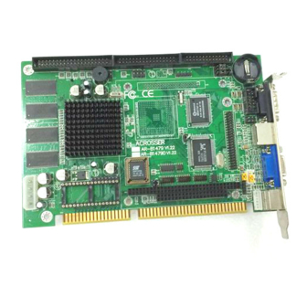
Dimensions: 185 mm x 122 mm (7.3”x4.8”) 1.2 PACKING LIST Some accessories are included with the system. Before AR-B1479 has been installed, please take a moment to make sure that the following items have been included inside the AR-B1479 package. -
Page 8: Features
1.4 POINT FOR ATTENTION The AR-B1479 CPU is a consumer II with C4 as a version that included some bugs on it. The effect is the use of floppy in WIN95 would be unable. The bug can be revised in CPU with C5 as a version. But according to ST as the original manufacturer, C5 just can normally be produced at least in October. -
Page 9: System Controller
PCI Master/Slave/Arbiter 2.1 POWERFUL X86 PROCESSOR The AR-B1479 uses the Consumer II/Elite PC-133 BGA, it is an advanced 64-bit x86 processor block compatible processor offering high performance, fully accelerated 2D graphics, a 64-synchronous DRAM controller, all on a single chip. It includes a 64-bit SDRAM controller, a high speed PCI local-bus controller and Industry standard PC chip set functions (Interrupt controller, DMA Controller, Interval timer and ISA BUS). -
Page 10: 64-Bit Sdram Uma Controller
AR-B1479 User’s Guide 2.2 64-BIT SDRAM UMA CONTROLLER 64-bit data bus. Up to100 MHz SDRAM clock speed. Integrated system memory, graphic frame memory and video frame memory. Supports 2MB up to 128 MB system memory Supports 16-, 64-, and 128-Mbit SDRAMs. -
Page 11: Crt Controller
AR-B1479 User’s Guide This chapter defines the STPC Consumer-II Strap Options and their location. Some strap options are left programmable for future versions of silicon. Strap Options 2.3 CRT CONTROLLER Integrated 135 MHz triple RAMDAC allowing for 1280 x 1024 x 75 Hz displays. -
Page 12: Graphics Engine
AR-B1479 User’s Guide 2.4 2D GRAPHICS ENGINE 64-bit windows accelerator. Backward compatibility to SVGA standards. Hardware acceleration for text, bitblts, transparent blts and fills Up to 64 x 64 graphics hardware cursor. Up to 4MB long linear frame buffer. 8-, 16-, 24-and 32-bit pixels. -
Page 13: Dma Controller
AR-B1479 User’s Guide 2.6 DMA CONTROLLER DMA channel 2X8237/AT compatible 7-channel DMA controller. 2X8259/AT compatible interrupt Controller. 16 interrupt inputs – ISA and PCI. Three 8254 compatible Timer/Counters. Co-processor error support logic. The figure below describes a complete implementation of the external glue logic for DMA Request time- multiplexing and DMA Acknowledge demultiplexing. -
Page 14: Timer / Counters
AR-B1479 User’s Guide 2.7 TIMER / COUNTERS System Activity Detection. Three power down timers. Doze timer for detecting lack of system activity for short durations. Stand-by timer for detecting lack of system activity for medium durations. Suspend timer for detecting lack of system activity for long durations. -
Page 15: Pci Master / Slave / Arbiter
AR-B1479 User’s Guide 2.11 PCI MASTER / SLAVE / ARBITER Fully compliant with PCI 2.1 specification. Integrated PCI arbitration interface. Up to 3 masters can connect directly. External PAL allows for greater then 3 masters. Translation of PCI cycles to ISA bus. -
Page 16: Setting Up The System
Overview System Setting 3.1 OVERVIEW AR-B1479 is a Pentium Grade CPU Board, which supports Ethernet, DOC, SSD, and Compact Flash (AR-B9462A) functions. This section provides the hardware’ s jumper settings, the connectors’ locations, and the pin assignments. External System Location 3.2 SYSTEM SETTING... -
Page 17: Hard Disk (Ide) Connector
AR-B1479 User’s Guide 3.2.1 Hard Disk (IDE) Connector (1) 40-Pin Hard Disk (IDE) Connector (IDE1) A 40-pin header type connector (IDE1) is provided to interface with up to two embedded hard disk drives (IDE AT bus). This interface, through a 40-pin cable, allows the user to connect up to two drives in a “daisy chain” fashion. -
Page 18: Fdd Port Connector (Cn4)
AR-B1479 User’s Guide (2) 44-Pin Hard Disk (IDE) Connector (IDE2) AR-B1479 also provides 44-pin connector (IDE2) interface to connect with the hard disk device. Furthermore, user could also apply AR-B9462A (option) to connect with Compact Flash storage device. Signal Signal... -
Page 19: Ethernet Rj-45 Connector (Lan1)
To use the PS/2 interface, an adapter cable has to be connected to the CN2 (6-pin header type) connector. This adapter cable is mounted on a bracket and is included in your AR-B1479 package. The connector for the PS/2 KB/mouse is a Mini-DIN 6-pin connector. Pin assignments for the PS/2 port connector are as follows:... -
Page 20: Power Connector (Pwr1)
AR-B1479 User’s Guide 3.2.7 Power Connector (PWR1) The PWR1 is a 4-pin power connector. It’ s the standard connector on all Acrosser boards. 4 +5V 3 GND 2 GND 1 +12V PWR1 PWR1: 4-Pin Power Connector 3.2.8 CRT Connector (DB1) -
Page 21: Lcd Panel Display Connector (Lcd1)
AR-B1479 User’s Guide 3.2.10 LCD Panel Display Connector (LCD1) Attach a display panel connector to this 44-pin connector with pin assignments as shown below: (Only for AR-B1479B) Figure 0-4 LCD1: LCD Display Connector Signal Signal SHFCLK +12V +12V ENABLK Table 0-2 LCD Display Pin Assignment... -
Page 22: Pc/104 Connector
AR-B1479 User’s Guide 3.2.12 PC/104 Connector (1) 64-Pin PC/104 Connector Bus A & B (PC1A) 64-Pin PC/104 Connector Figure PC1A: 64-Pin PC/104 Connector Bus A & B PC104 -IOCHCK --- GND SD7 --- --- RSTDRV SD6 --- --- +5 VDC... -
Page 23: Parallel Port Connector (Cn3)
AR-B1479 User’s Guide 3.2.13 Parallel Port Connector (CN3) The connector for the parallel port is a 26 pins female connector. Signal Signal -Strobe -Auto Form Feed Data 0 -Error Data 1 -Initialize Data 2 -Printer Select In Data 3 Ground... -
Page 24: Com1, Com2 (Db2, Cn5)
AR-B1479 User’s Guide 3.2.17 COM1, COM2 (DB2, CN5) DB2 (COM1) CN5(COM2) Figure 0-5 DB2 & CN5: RS-232 Connector Signal Signal /DCD /CTS /DSR /DTR /RTS Table 0-3 RS-232 Connector Pin Assignment (1) RS-232/RS-485 Select for COM1 (P6 & P7) The P6&P7 jumper is used to choose between the use of the on-board RS-232 or RS-485 for the DB2 – COM1. -
Page 25: Touch Screen Connector (J6 & J7)
AR-B1479 User’s Guide (3) RS-485 Header (J9) 1. N485+ 2. N485- 3 2 1 3. GND 3.2.18 Touch Screen Connector (J6 & J7) 1. RXDF 2. TXDF 3 2 1 3. CGND Figure 0-8 J6&J7: Touch Screen Connector 3.2.19 D.O.C. Memory Bank Address Select (JP3) This section provides the information about how to use the D.O.C. -
Page 26: Atx Power External Bottom Connector (J2)
2 EXP 3.3 WATCHDOG TIMER This section describes the use of Watchdog Timer, including disable, enable, and trigger. AR-B1479 is equipped with a programmable time-out period watchdog timer that occupies I/O port 214H. Users can use simple program to enable the watchdog timer. Once you enable the watchdog timer, the program should trigger it every time before it times out. -
Page 27: Watchdog Timer Setting
AR-B1479 User’s Guide 3.3.1 Watchdog Timer Setting The watchdog timer is a circuit that maybe be used from your program software to detect crash or hang up. The Watchdog timer is automatically disabled after reset. Once you enabled the watchdog timer, your program should trigger the watchdog timer every time before it times out. - Page 28 AR-B1479 User’s Guide C:>debug O 443 88H Generally, watchdog function would generate IRQ 9 after 8 seconds O 443 83H Disable last watchdog function. Watchdog function would Generate IRQ 9 after 3 seconds. C:>debug O 443 CFH Generally, watchdog function would...
-
Page 29: Installation
4.2.1 Driver Installation Generally, the CD that comes with AR-B1479 should be able to carry out ‘ Auto run’ function, please follows the instruction displayed on the screen to install drives. In case, if the ‘ Auto run’ function is fail, please execute... -
Page 30: Bios Console
AR-B1479 User’s Guide 5. BIOS CONSOLE This chapter describes the AR-B1479 BIOS menu displays and explains how to perform common tasks needed to get up and running, and presents detailed explanations of the elements found in each of the BIOS menus. The... - Page 31 AR-B1479 User’s Guide CAUTION: 1. AR-B1479 BIOS the factory-default setting is used to the <Auto Configuration with Optimal Settings> Acrosser recommends using the BIOS default setting, unless you are very familiar with the setting function, or you can contact the technical support engineer.
-
Page 32: Standard Cmos Setup
AR-B1479 User’s Guide 5.2 STANDARD CMOS SETUP The <Standard CMOS Setup> option allows you to record some basic system hardware configuration and set the system clock and error handling. If the CPU board is already installed in a working system, you will not need to select this option anymore. -
Page 33: Advanced Cmos Setup
AR-B1479 User’s Guide 5.3 ADVANCED CMOS SETUP The <Advanced CMOS Setup> option consists of configuration entries that allow you to improve your system performance, or let you set up some system features according to your preference. Some entries here are required by the CPU board’... - Page 34 AR-B1479 User’s Guide Boot Up Num-Lock This item is used to activate the Num-Lock function upon system boot. If the setting is on, after a boot, the Num- Lock light is lit, and user can use the number key. Floppy Drive Swap The option reverses the drive letter assignments of your floppy disk drives in the Swap A, B setting, otherwise leave on the setting of Disabled (No Swap).
- Page 35 AR-B1479 User’s Guide Internal Cache This option specifies the caching algorithm used for L1 internal cache memory. The settings are: Setting Description Neither L1 internal cache memory on the CPU or L2 Disabled secondary cache memory is enabled. Use the write-back caching algorithm.
-
Page 36: Advanced Chipset Setup
AR-B1479 User’s Guide 5.4 ADVANCED CHIPSET SETUP This option controls the configuration of the board’ s chipset. Control keys for this screen are the same as for the previous screen. AMIBIOS SETUP - ADVANCED CHIPSET SETUP (C) 1998 American Megatrends, Inc. All Rights Reserved... -
Page 37: Power Management
AR-B1479 User’s Guide RAS Precharge Time The DRAM RAS precharge time. Time Insert Wait The DRAM time insert wait: RAS Active and CAS Precharge function setting. ISA High Speed The Speed field shows the speed at which the processor runs internally. -
Page 38: Pci/Plug And Play
AR-B1479 User’s Guide Hard Disk Time Out This option specifies the length of a period of hard disk inactivity. When this period expired, the hard disk drive enters the power-conserving mode specified on the <Hard Disk Power Down Mode> option. -
Page 39: Peripheral Setup
Enabled F2/F3:Color Figure 0-9 BIOS: Peripheral Setup OnBoard FDC This option enables the floppy drive controller on the AR-B1479. OnBoard Serial Port This option enables the serial port on the AR-B1479. OnBoard Parallel Port This option enables the parallel port on the AR-B1479. -
Page 40: Auto-Detect Hard Disks
AR-B1479 User’s Guide Parallel Port DMA Channel This option is only available if the setting for the parallel Port Mode option is ECP. OnBoard PCI MASTER/SLAVE Prefetch This option specifies the onboard IDE controller channels that will be used. 5.8 AUTO-DETECT HARD DISKS This option detects the parameters of an IDE hard disk drive, and automatically enters them into the Standard CMOS Setup screen. -
Page 41: Save Settings And Exit
AR-B1479 User’s Guide 5.11.1 Save Settings and Exit This item is in the <Standard CMOS Setup>, <Advanced CMOS Setup>, <Advanced Chipset Setup> and the new password (if it has been changed) will be stored in the CMOS. The CMOS checksum is calculated and written into the CMOS. -
Page 42: Bios Update
The chips can be electronically reprogrammed, allowing you to upgrade your BIOS firmware without removing and installing chips. The AR-B1479 provides FLASH BIOS update function for you to easily upgrade newer BIOS version. Please follow the operating steps for updating new BIOS: Step 1: Turn on your system and don’...
Need help?
Do you have a question about the AR-B1479 and is the answer not in the manual?
Questions and answers