
Related Manuals for Acrosser Technology AR-B1631


Summary of Contents for Acrosser Technology AR-B1631
- Page 1 AR-B1631 User’s Guide AR-B1631 AMD GX3 , VGA , LAN , PC104+ , 4COM , 4 USB User’ s Guide Edition: 1.1...
- Page 2 VARs that want to provide all the performance, reliability, and quality at a reasonable price. In addition, the AR-B1631 provides on chip VGA. The VGA, which provides up to True Color (32 bit) 1024x768, or High Color (16 bit) 1280x1024 resolution. The VGA memory is share main memory (2M, 4M, or 8M). AR-B1631 also has 18-bit LVDS function in the system.
-
Page 3: Specifications
AR-B1631 User’s Guide SPECIFICATIONS CPU: GX3 Chipset: CS5536 or CS5535 RAM memory: Supports DDRA, on-board 200-pin SO-DIMM up to 512MB DDRAM memory module Display Interface: CRT – D-SUB 15-pin female connector LVDS – for 18 bit TFT LCD Panel. Ultra ATA/33/66/100 IDE Interface: Floppy disk drive interface: 2.88 MB, 1.44MB, 1.2MB, 720KB, or 360KB floppy disk drive. -
Page 4: Setting Up System
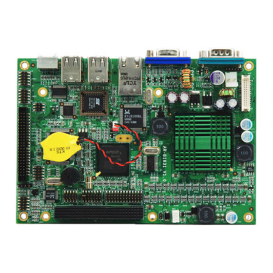
AR-B1631 User’s Guide 2. SETTING UP SYSTEM This chapter describes how to install the AR-B1631. At first, the layout of AR-B1631 is shown, and the unpacking information that you should be careful is described. Overview System Settings 2.1 AR-B1631 OVERVIEW... -
Page 5: System Settings
Press the jumper evenly onto the pins. Be careful not to bend the pins. We will show the locations of the AR-B1631 jumper pins, and the factory-default settings. CAUTION: Do not touch any electronic components unless you are safely grounded. -
Page 6: Audio1 (Audio)
AR-B1631 User’s Guide 2.2.3 JP2 (RESET) RESET BUTTON PIN HEADER 2.2.4 DIO1 (GPIO) XOUT0 XOUT1 XOUT2 XOUT3 XIN0 XIN1 XIN2 XIN3 2.2.5 AUDIO1 (AUDIO) LINE OUT R LINE OUT L LINE IN R LINE IN L MIC IN 2.2.6 COM2, COM3, COM4 (RS232) 2.2.7... -
Page 7: Cn10 (Lcd Setting)
AR-B1631 User’s Guide 2.2.8 J3 (CLEAR CMOS) NORMAL CLEAR CMOS 2.2.9 CN10 (LCD SETTING) -SHFCLK SHFCLK 3.3V LCD 5V LCD 2.2.10 CDIN1 (CDIN) CD_L CD_R 2.2.11 CN9 (POWER) +12V 2.2.12 CN8 (STAND BY POWER) +5V STANDBY PSON# 2.2.13 J5 (LCD BACKLIGHT) -
Page 8: Lpt1 (Parallel Port)
AR-B1631 User’s Guide 2.2.14 JP4 (LCD LVDS) POWER LVDS_TXC+ LVDS_TXC- LVDS_TX2- LVDS_TX2+ LVDS_TX1+ LVDS_TX1- LVDS_TX0- LVDS_TX0+ LVDS_TX3- LVDS_TX3+ POWER POWER 2.2.15 LPT1 (PARALLEL PORT) STB- AFD- ERROR- INIT- SLIN- ACK- BUSY SELECT 2.2.16 BT1 (BATTERY CONNECTOR) AND BATTERY POSITIVE BATTERY NEGATIVE BATTERY 2.2.18... - Page 9 AR-B1631 User’s Guide 2.2.19 J4 (PC104+) A1 B1 C1 D1 SERIRQ C/BE0# AD11 AD10 AD14 AD13 AD12 +3.3V C/BE1# AD15 +3.3V SERR# PULL UP PERR# +3.3V PULL UP STOP# +3.3V LOCK# +3.3V TRDY# DEVSEL# FRAME# IRDY# +3.3V AD16 +3.3V C/BE2# AD18 +3.3V...
-
Page 10: Lcd Flat Panel Display
AR-B1631 User’s Guide 3. LCD FLAT PANEL DISPLAY This chapter describes the configuration and installation procedures for LCD displays. LVDS1 AR-B1631 Panel Backlight connect to J5 Backlight Power Inverter LCD Panel Block Diagram Please visit our web site or contact with our technical support department for supports of LCD connecting. -
Page 11: Bios Console
AR-B1631 User’s Guide 4. BIOS CONSOLE This chapter describes the AR-B1631 BIOS menu displays and explains how to perform common tasks needed to get up and running, and presents detailed explanations of the elements found in each of the BIOS menus. The... - Page 12 AR-B1631 User’s Guide Date & Time Setup Highlight the <Date> field and then press the [Page Up] /[Page Down] or [+]/[-] keys to set the current date. Follow the month, day and year format. Highlight the <Time> field and then press the [Page Up] /[Page Down] or [+]/[-] keys to set the current date.
- Page 13 AR-B1631 User’s Guide Power Management[ACPI] This allows you to enable or disable the ACPI function Configuration options: [Disabled] [ACPI] CPU / MEM / PCI Frequency [Auto] This allows you to setting CPU, memory and PCI frequency. Configuration options: 333 / 266 / 33...
- Page 14 AR-B1631 User’s Guide RXD, TXD Active [Hi, Lo] Choose how system will recognize RXD and TXD signal on your serial port. Configuration options: [Hi, Hi] [Hi, Lo] [Lo, Hi] [Lo, Lo] IR Transmission Delay [Enable] This allows you to enable IR Transmission Delay.
- Page 15 AR-B1631 User’s Guide 4.4PnP/PCI PnP/PCI Reset Configuration Data [Disable] Normally, you leave this field Disabled. Select Enabled to reset Extended System Configuration Data (ESCD) when you exit Setup if you have installed a new add-on and the system reconfiguration has caused such a serious conflict that the operating system cannot boot.
- Page 16 AR-B1631 User’s Guide 4.5 BOOT BOOT First/Second/Third Boot Device HDD-0 SCSI CDROM HDD-1 USB-FDD USB-ZIP USB-CDROM USB-HDD Disabled Boot Other Device [Enabled] Configuration options: [Enabled] [Disabled].
-
Page 17: Bios Exit
AR-B1631 User’s Guide 4.6 BIOS EXIT Exit When you have made all of your selections from the various menus in the Setup program, save your changes and exit Setup. Select Exit from the menu bar to display the following menu. - Page 18 AR-B1631 User’s Guide 5. I/O address、IRQ and Memory Mapping 5.1 I/O address Mapping...
- Page 19 AR-B1631 User’s Guide 5.2 IRQ Mapping 5.3 Memory Mapping...
-
Page 20: Gpio Sample Code
AR-B1631 User’s Guide 6. GPIO Sample Code /*[]======================================================================[]*/ /*|| GPIO Test utility for W83627HF. ||*/ /*|| Date : 10/18/2005 ||*/ /*|| Author : Willy ||*/ /*[]======================================================================[]*/ /*[]======================================================================[]*/ /*|| Include files ||*/ /*[]======================================================================[]*/ #include <conio.h> #include <stdio.h> /*[]======================================================================[]*/ /*|| Assember Types Define... - Page 21 AR-B1631 User’s Guide Read_Byte=inportb(IO_PORT_BASE+1); if(Read_Byte&0x01) //GPI10 Show_Byte=Show_Byte|0x01; else Show_Byte=Show_Byte&0xFE; if(Read_Byte&0x02) //GPI11 Show_Byte=Show_Byte|0x02; else Show_Byte=Show_Byte&0xFD; if(Read_Byte&0x04) //GPI12 Show_Byte=Show_Byte|0x04; else Show_Byte=Show_Byte&0xFB; if(Read_Byte&0x08) //GPI13 Show_Byte=Show_Byte|0x08; else Show_Byte=Show_Byte&0xF7; if(Read_Byte&0x10) //GPI14 Show_Byte=Show_Byte|0x10; else Show_Byte=Show_Byte&0xEF; if(Read_Byte&0x20) //GPI15 Show_Byte=Show_Byte|0x20; else Show_Byte=Show_Byte&0xDF; if(Read_Byte&0x40) //GPI16 Show_Byte=Show_Byte|0x40; else Show_Byte=Show_Byte&0xBF; if(Read_Byte&0x80) //GPI17 Show_Byte=Show_Byte|0x80;...
- Page 22 AR-B1631 User’s Guide printf("\n>>>>> GPI Test Error <<<<<\n"); return 1; } // return fail printf("\n>>>>> GPI Test End <<<<<\n"); return 0; // return pass /*[]======================================================================[]*/ /*|| Function : GPO_TEST() ||*/ /*|| Input : BYTE IO_PORT_BASE ||*/ /*|| Change ||*/ /*|| Return : Pass return "0", Fail return "1".
- Page 23 AR-B1631 User’s Guide if ( argc != 2 ) { Show_Title(); return 1; } clrscr(); // Enter W83627HF Config Enter_Config(IO_PORT_BASE); Init_SIO(IO_PORT_BASE); switch(argv[1][0]) case 'i': case 'I': //I Key result=GPI_TEST(IO_PORT_BASE); if(result==0) printf("Test Result is Pass."); else printf("Test Result is Fail."); break;...
- Page 24 AR-B1631 User’s Guide char YES_NO_Confirm() int X_Axis,Y_Axis; char y_n; X_Axis=wherex(); /* Get Cursor X Axis */ Y_Axis=wherey(); /* Get Cursor Y Axis */ while(1) { y_n=getche(); if(y_n=='y' || y_n=='Y') return('y'); else if(y_n=='n' || y_n=='N') return('n'); else gotoxy(X_Axis,Y_Axis); /*[]======================================================================[]*/ /*|| Function...
- Page 25 AR-B1631 User’s Guide outportb(IO_PORT_BASE,0x07); outportb(IO_PORT_BASE+1,0x07); // Set GPIO Port Active outportb(IO_PORT_BASE,0x30); outportb(IO_PORT_BASE+1,0x01);...
Need help?
Do you have a question about the AR-B1631 and is the answer not in the manual?
Questions and answers