
Related Manuals for Acrosser Technology AR-B1375


Summary of Contents for Acrosser Technology AR-B1375
- Page 1 AR-B1375/AR-B1376 Half Size All-In-One 386SX CPU CARD User’ s Guide Edition: 1.4 Book Number: AR-B1376-97.B06...
-
Page 3: Table Of Contents
AR-B1375/AR-B1376 User¡ ¦ s Guide Table of Contents PREFACE............................... 0-3 COPYRIGHT NOTICE AND DISCLAIMER ..........................0-3 WELCOME TO THE AR-B1375/AR-B1376 CPU BOARD......................0-3 BEFORE YOU USE THIS GUIDE...............................0-3 RETURNING YOUR BOARD FOR SERVICE..........................0-3 TECHNICAL SUPPORT AND USER COMMENTS ........................0-3 ORGANIZATION..................................0-4 STATIC ELECTRICITY PRECAUTIONS............................0-4 OVERVIEW.............................. - Page 4 AR-B1375/AR-B1376 User¡ ¦ s Guide SOLID STATE DISK ............................6-1 OVERVIEW....................................6-1 SWITCH SETTING..................................6-1 6.2.1 Overview ....................................6-2 6.2.2 I/O Port Address Select (SW1-1)............................6-2 6.2.3 SSD Firmware Address Select (SW1-2)..........................6-2 6.2.4 SSD Drive Number (SW1-3 & SW1-4) ..........................6-3 6.2.5 ROM Type Select (SW1-5 & SW1-6)..........................6-4 JUMPER SETTING ..................................6-5...
-
Page 5: Preface
B1375/AR-B1376. You also could find general system information here. 0.3 BEFORE YOU USE THIS GUIDE If you have not already installed this AR-B1375/AR-B1376, refer to the Chapter 3, “Setting Up the System” in this guide. Check the packing list, make sure the accessories in the package. -
Page 6: Organization
AR-B1375/AR-B1376 User¡ ¦ s Guide 0.6 ORGANIZATION This information for users covers the following topics (see the Table of Contents for a detailed listing): Chapter 1, “Overview,” provides an overview of the system features and packing list. Chapter 2, “System Controller,” describes the major structure. -
Page 7: Overview
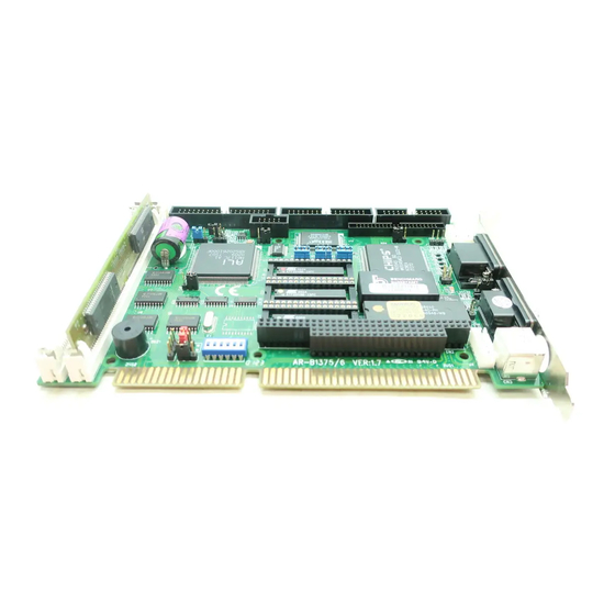
1.1 INTRODUCTION The AR-B1375 and AR-B1376 are new generation half size, 386 ISA card. This card offers much greater performance than the older cards such as support for 32MB’ s of DRAM using two 72-pin SIMMs, one RS-232C/485 and one RS-232C port and 3/1.5MB solid state disk capacity for ROM, FLASH and SRAM. -
Page 8: Features
80386SX-33/40 MHz CPU ISA and PC/104 extension bus Up to 32MB DRAM system On-board CRT and LCD panel display (AR-B1375 doesn’ t provide this function) Supports IDE hard disk drives Supports floppy disk drives Supports 1 bi-directional parallel port... -
Page 9: System Controller
Parallel Port 2.1 MICROPROCESSOR The AR-B1375 and AR-B1376 use the ALI M6117 CPU, it is designed to perform like Intel’ s 386SX system with deep green features. The 386SX core is the same as M1386SX of Acer Labs. Inc. and 100% object code compatible with the Intel 386SX microprocessor. -
Page 10: Keyboard Controller
2.4 INTERRUPT CONTROLLER The equivalent of two 8259 Programmable Interrupt Controllers (PIC) are included on the AR-B1375/AR-B1376 board. They accept requests from peripherals, resolve priorities on pending interrupts in service, issue interrupt requests to the CPU, and provide vectors which are used as acceptance indices by the CPU to determine which interrupt service routine to execute. -
Page 11: I/O Port Address Map
AR-B1375/AR-B1376 User¡ ¦ s Guide 2.4.1 I/O Port Address Map Hex Range Device 000-01F DMA controller 1 020-021 Interrupt controller 1 022-023 ALI M6117 040-04F Timer 1 050-05F Timer 2 060-06F 8042 keyboard/controller 070-071 Real-time clock (RTC), non-maskable interrupt (NMI) - Page 12 AR-B1375/AR-B1376 User¡ ¦ s Guide I/O Pin Signal Name Input/Output I/O Pin Signal Name Input/Output SA14 Input/Output -DACK1 Output SA13 Input/Output DRQ1 Input SA12 Input/Output -REFRESH Input/Output SA11 Input/Output BUSCLK Output SA10 Input/Output IRQ7 Input Input/Output IRQ6 Input Input/Output IRQ5...
-
Page 13: Real-Time Clock And Non-Volatile Ram
AR-B1375/AR-B1376 User¡ ¦ s Guide 2.5 REAL-TIME CLOCK AND NON-VOLATILE RAM The AR-B1375/AR-B1376 contains a real-time clock compartment that maintains the date and time in addition to storing configuration information about the computer system. It contains 14 bytes of clock and control registers and 114 bytes of general purpose RAM. -
Page 14: Serial Port
AR-B1375/AR-B1376 User¡ ¦ s Guide 2.7 SERIAL PORT The ACEs (Asynchronous Communication Elements ACE1 to ACE4) are used to convert parallel data to a serial format on the transmit side and convert serial data to parallel on the receiver side. The serial format, in order of transmission and reception, is a start bit, followed by five to eight data bits, a parity bit (if programmed) and one, one and half (five-bit format only) or two stop bits. - Page 15 AR-B1375/AR-B1376 User¡ ¦ s Guide (5) Line Control Register (LCR) Bit 0: Word Length Select Bit 0 (WLS0) Bit 1: Word Length Select Bit 1 (WLS1) WLS1 WLS0 Word Length 5 Bits 6 Bits 7 Bits 8 Bits Bit 2: Number of Stop Bit (STB)
-
Page 16: Parallel Port
AR-B1375/AR-B1376 User¡ ¦ s Guide (9) Divisor Latch (LS, MS) Bit 0: Bit 0 Bit 8 Bit 1: Bit 1 Bit 9 Bit 2: Bit 2 Bit 10 Bit 3: Bit 3 Bit 11 Bit 4: Bit 4 Bit 12... - Page 17 AR-B1375/AR-B1376 User¡ ¦ s Guide (4) Printer Status Buffer The system microprocessor can read the printer status by reading the address of the Printer Status Buffer. The bit definitions are described as follows: -ERROR SLCT -ACK -BUSY Figure 2-2 Printer Status Buffer NOTE: X presents not used.
-
Page 19: Setting Up The System
Overview System Setting 3.1 OVERVIEW The AR-B1375 and AR-B1376 are all-in-one half size, Pentium single CPU board. This section provides hardware’ s jumpers setting, the connectors’ locations, and the pin assignment. CAUTION: The CPU board doesn’ t support the type DRAM SIMM of two-sided, it only supports single side DRAM SIMM. -
Page 20: System Setting
Press the jumper evenly onto the pins. Be careful not to bend the pins. We will show the locations of the AR-B1375 and AR-B1376 jumper pins, and the factory-default setting. CAUTION: Do not touch any electronic component unless you are safely grounded. Wear a grounded wrist strap or touch an exposed metal part of the system unit chassis. -
Page 21: Pc/104 Connector
AR-B1375/AR-B1376 User¡ ¦ s Guide 3.2.2 PC/104 Connector (1) 40-Pin PC/104 Connector Bus C & D (CN1) 40 Pin PC/104 Connector Figure 3-4 CN1: 40-Pin PC/104 Connector Bus C & D GND --- --- GND -SBHE --- --- -MEM16 LA23 ---... - Page 22 AR-B1375/AR-B1376 User¡ ¦ s Guide (3) I/O Channel Signal Description Name Description BUSCLK [Output] The BUSCLK signal of the I/O channel is asynchronous to the CPU clock. RSTDRV [Output] This signal goes high during power-up, low line-voltage or hardware reset SA0 - SA19 The System Address lines run from bit 0 to 19.
-
Page 23: Hard Disk (Ide) Connector (Cn4)
AR-B1375/AR-B1376 User¡ ¦ s Guide Name Description -MASTER [Input] The MASTER is the signal from the I/O processor which gains control as the master and should be held low for a maximum of 15 microseconds or system memory may be... -
Page 24: Fdd Port Connector (Cn5)
To use the parallel port, an adapter cable has connected to the CN6 (26-pin header type) connector. This adapter cable is mounted on a bracket and is included in your AR-B1375 or AR-B1376 package. The connector for the parallel port is a 25 pin D-type female connector. -
Page 25: Serial Port
AR-B1375/AR-B1376 User¡ ¦ s Guide 3.2.6 Serial Port (1) RS-232/RS-485 Select for COM-B (JP2) JP2 select the on-board RS-232/RS-485 for COM B, if choose RS-232 connecting with CN7; if choose RS-485 connecting with J9. 1 2 3 1 2 3... -
Page 26: Reset Header (J1)
(5) RS-232C Connector (CN7 & DB2) There are two serial ports with EIA RS-232C interface on the AR-B1375 or AR-B1376. COM A uses one on-board D-type 9-pin male connector (DB2) which is located at the right side of the card, and COM B uses one 10-pin header (CN7) which is located at the upper of the card. -
Page 27: Power Connector (J3)
AR-B1375/AR-B1376 User¡ ¦ s Guide (3) Watchdog LED Header (J10) LED+ LED- Figure 3-19 J10: Watchdog LED Header 3.2.9 Power Connector (J3) J3 is a 8-pin power connector, you can directly connect the power supply to the on board power connector for stand alone applications. -
Page 28: Cpu Base Clock Select (Jp1)
(2) External Battery Connector (J11) J11 allows users to connector an external 4.5 to 6 VDC battery to the AR-B1375 and AR-B1376 if the on-board battery is fully discharged. The SRAM disk will draw the battery current. The battery charger on AR-B1375 and AR-B1376 doesn’... -
Page 29: Crt/Lcd Flat Panel Display
AR-B1375/AR-B1376 User¡ ¦ s Guide 4. CRT/LCD FLAT PANEL DISPLAY This section describes the configuration and installation procedure using LCD and CRT display. Connecting the CRT Monitor LCD Flat Panel Display Supported LCD Panel 4.1 CONNECTING THE CRT MONITOR 4.1.1 VGA Setting (JP5) -
Page 30: Crt Connector (Cn13)
DB1 is used to connect with a VGA monitor when you are using the on-board VGA controller as display adapter. Pin assignments for the DB1 connector is as follows: NOTE: DB1 on the AR-B1375 is not functional, always the function is used on the AR-B1376 CPU board. DB1 (CRT Connector) -
Page 31: Inverter Board Description
Figure 4-4 JP6: DE/E Signal from M or LP Select (2) LCD Control Connector (CN9) CN9 is a 5-pin connector that attaches to the Contrast and Backlight board, Its pin assignment is shown below: NOTE: AR-B1375 doesn’ t provide this function. ENABLK ENVEE... -
Page 32: Supported Lcd Panel
AR-B1375/AR-B1376 User¡ ¦ s Guide (3) LCD Panel Display Connector (CN8) Attach a display panel connector to this 44-pin connector with pin assignments as shown below: NOTE: AR-B1375 doesn’ t provide this function. Figure 4-6 CN8: LCD Display Connector Signal... -
Page 33: Installation
There are two diskettes: disk 1 is for WIN31 & MS-DOS VGA resolution, disk 2 is for WIN95 and SSD utility. Every diskette attach the README.* file. The AR-B1375 attached the SSD utility only, if you use the AR-B1375 skip the... -
Page 34: Vga Driver
AR-B1375/AR-B1376 User¡ ¦ s Guide 5.2.1 VGA Driver (1) WIN 3.1 Driver For the WIN31 operation system, user must in the DOS mode decompress the compress file. And then as to the steps: Step 1: In the DOS mode execute the SETUP.EXE file. -
Page 35: Ssd Utility
AR-B1375/AR-B1376 User¡ ¦ s Guide 5.2.2 SSD Utility To support the AR-B1375/AR-B1376 solid state disk’ s operations, the following files have been provided on the enclosed diskette’ s directory <SSD>. (A) PGM137x.EXE PGM137x.EXE PGM137x.EXE is used to program the 12V FLASH EPROM after the ROM pattern files are generated by RFG.EXE The PGM137x.EXE can also program the correctness of the ROM... - Page 36 NOTE: If you want to use AR-B137x with any DOS which is not supported by RFG, please send your requirement to Acrosser Technology Co., Ltd. or ontract with your local sales representative. The RFG.EXE provided in the utility diskette is a program that converts the files you list in the PGF and convert them into ROM pattern file.
-
Page 37: Write Protect Function
5.3 WRITE PROTECT FUNCTION The AR-B1375 and AR-B1376 provide hardware and software write protect functions for small page 5V FLASH disk and only software write protected function for SRAM disk. This is to prevent your data on 5V FLASH or SRAM disk from accidental deletion or overwrite. -
Page 38: Hardware Write Protect
AR-B1375/AR-B1376 User¡ ¦ s Guide 5.3.1 Hardware Write Protect To enable the hardware protect function for small page 5V FLASH disk, please refer to the “Switch Setting”. 5.3.2 Software Write Protect If you need the write protect function and sometimes you have to write or update data on your FLASH/SRAM disk, you can use the software write protect instead of hardware write protect. -
Page 39: Watchdog Timer
This section describes how to use the Watchdog Timer, disabled, enabled, and trigger. The AR-B1375/AR-B1376 is equipped with a programmable time-out period watchdog timer. User can use the program to enable the watchdog timer. Once you have enabled the watchdog timer, the program should trigger it every time before it times out. -
Page 40: Watchdog Timer Enabled
AR-B1375/AR-B1376 User¡ ¦ s Guide NOTE: 1. If you program the watchdog to generate IRQ15 signal when it times out, you should initial IRQ15 interrupt vector and enable the second interrupt controller (8259 PIC) in order to enable CPU to process this interrupt. -
Page 41: Solid State Disk
6.1 OVERVIEW The AR-B1375 and AR-B1376 provides three 32-pin JEDEC DIP sockets which may be populated with up to 3MB of EPROM or 1.5MB of FLASH or 1.5MB of SRAM disk. It is ideal for diskless systems, high reliability and/or high speed access applications, controller for industrial or line test instruments, and etc. -
Page 42: Overview
6.2.3 SSD Firmware Address Select (SW1-2) The AR-B1375‘ s and AR-B1376’ s SSD firmware occupies 8KB of memory. SW1-2 is used to select the memory base address. You must select an appropriate address so that the AR-B1375 or AR-B1376 will not conflict with memory installed on other add-on memory cards. -
Page 43: Ssd Drive Number (Sw1-3 & Sw1-4)
Table 6-4 SSD Drive Number for Simulate 2 Disk Drive NOTE: 1. If there is no DOS on this SSD, the disk number will be 1 (B:). If any DOS is found by the AR-B1375/AR- B1376 SSD BIOS, the disk letter will be 0 (A:). But, you can change the disk number from 0 to 1 by pressing the <ESC>... -
Page 44: Rom Type Select (Sw1-5 & Sw1-6)
AR-B1375/AR-B1376 User¡ ¦ s Guide (2) Disk Drive Name Arrangement If any logical hard disk drives exist in your system, there will also be a different disk number depending on which version DOS you are using. The solid state disk drive number with there respective DOS drive designation are listed in table as follows. The solid state disk drive number is changeable as the DOS version. -
Page 45: Jumper Setting
Before installing the memory into memory sockets MEM1 through MEM3 (U31, U32 and U33 respectively), you have to configure the memory type which will be used (ROM/RAM) on the AR-B1375 and AR-B1376. Each socket is equipped with an jumper to select the memory type. -
Page 46: Rom Disk Installation
AR-B1375/AR-B1376 User¡ ¦ s Guide 6.4 ROM DISK INSTALLATION The section describes the various type SSDs’ installation steps as follows. The jumper and switch adjust as SSD’ s different type to set. 6.4.1 UV EPROM (27Cxxx) (1) Switch and Jumper Setting Step 1: Use jumper block to set the memory type as ROM (FLASH). -
Page 47: Large Page 5V Flash Disk
AR-B1375/AR-B1376 User¡ ¦ s Guide (2) Software Programming Use the UV EPROM, please refer to the follow steps: Step 1: Turn on the power and boot DOS from hard disk drive or floppy disk drive. Step 2: Making a Program Group File (*.PGF file) Step 3: Using the RFG.EXE to generate ROM pattern files, and counting the ROM numbers as the pattern... - Page 48 Step 4: Turn on your system, and Program FLASH EPROMs. NOTE: The FLASH EPROM program is built-in the AR-B1375/AR-B1376 board. The FLASH EPROMs can be programmed on the AR-B1375/AR-B1376. Before programming the FLASH EPROMs, please insert at least the same number of FLASH EPROMs, please insert at least the same number of FLASH EPROMs, please insert at least the same number of FLASH chips as the ROM pattern files generated.
-
Page 49: Small Page 5V Flash Rom Disk
AR-B1375/AR-B1376 User¡ ¦ s Guide 6.4.3 Small Page 5V FLASH ROM Disk (1) Switch and Jumper Setting Step 1: Use jumper block to set the memory type as ROM (FLASH). Step 2: Select the proper I/O base port, firmware address, disk drive number and EPROM type on SW1. -
Page 50: Ram Disk
AR-B1375/AR-B1376 User¡ ¦ s Guide (3) Typing DOS Command You can use another way to format and copy files to the 5V FLASH EPROM. This method provides the convenience of using a RAM disk. You can use the DOS <FORMAT> and <COPY> command to format and copy files. -
Page 51: Combination Of Rom And Ram Disk
RFG.EXE to program ROM pattern files. NOTE: Users can only boot DOS from the ROM disk drive if the AR-B1375/AR-B1376 is configured as a ROM and a RAM disk. You don’ t need to copy DOS onto the RAM disk. -
Page 53: Bios Console
AR-B1375/AR-B1376 User¡ ¦ s Guide 7. BIOS CONSOLE This chapter describes the AR-B1375/AR-B1376 BIOS menu displays and explains how to perform common tasks needed to get up and running, and presents detailed explanations of the elements found in each of the BIOS menus. -
Page 54: Standard Cmos Setup
AR-B1375/AR-B1376 User¡ ¦ s Guide 7.2 STANDARD CMOS SETUP The <Standard CMOS Setup> option allows you to record some basic system hardware configuration and set the system clock and error handling. If the CPU board is already installed in a working system, you will not need to select this option anymore. -
Page 55: Advanced Cmos Setup
AR-B1375/AR-B1376 User¡ ¦ s Guide 7.3 ADVANCED CMOS SETUP The <Advanced CMOS SETUP> option consists of configuration entries that allow you to improve your system performance, or let you set up some system features according to your preference. Some entries here are required by the CPU board¡... - Page 56 AR-B1375/AR-B1376 User¡ ¦ s Guide System Keyboard This function specifies that a keyboard is attached to the computer. Primary Display The option is used to set the type of video display card installed in the system. Password Check This option enables password checking every time the computer is powered on or every time the BIOS Setup is executed.
-
Page 57: Advanced Chipset Setup
AR-B1375/AR-B1376 User¡ ¦ s Guide OnBoard FDC This option enables the floppy drive controller on the AR-B1375 and AR-B1376. OnBoard Serial Port This option enables the serial port on the AR-B1375 and AR-B1376. OnBoard Parallel Port This option enables the parallel port on the AR-B1375 and AR-B1376. -
Page 58: Password Setting
AR-B1375/AR-B1376 User¡ ¦ s Guide Time Insert Wait The DRAM time insert wait: RAS Active and CAS Precharge function setting. Memory Write Insert Wait ISA bus memory write insert wait ISA High Speed The Speed field shows the speed at which the processor runs internally. -
Page 59: Auto Configuration With Fail Safe Setting
The chips can be electronically reprogrammed, allowing you to upgrade your BIOS firmware without removing and installing chips. The AR-B1375/AR-B1376 provides FLASH BIOS update function for you to easily upgrade newer BIOS version. Please follow the operating steps for updating new BIOS: Step 1: Turn on your system and don’... - Page 60 AR-B1375/AR-B1376 User¡ ¦ s Guide Flash EPROM Programming is going to start. System will not be usable until Programming of Flash EPROM is successfully complete. In case of any error, existing Flash EPROM must be replaced by new program Flash EPROM.
-
Page 61: Specifications & Ssd Types Supported
HITACHI HM628512 (512Kx8, 4M bits) UPD434000 (512Kx8, 4M bits) SONY CXK584000P/M (512Kx8, 4M bits) The following list contains large page 5V FLASHs supported by the AR-B1375/AR-B1376: Am29F512 (64Kx8, 512K bits) Am29F010 (128Kx8, 1M bits) Am29F020 (256Kx8, 2M bits) Am29F040 (512Kx8, 4M bits) - Page 62 AR-B1375/AR-B1376 User¡ ¦ s Guide The following list contains small page 5V FLASHs supported by the AR-B1375/AR-B1376: ATMEL AT29C512 (64Kx8, 512K bits) PH29EE512 (64Kx8, 512K bits) ATMEL AT29C010 (128Kx8, 1M bits) 28EE010 (128Kx8, 1M bits) 28EE011 (128Kx8, 1M bits) PH29EE010...
-
Page 63: Using Memory Banks
On every chip, the memory bank number starts from zero. The last memory bank number depends on the size of the memory chip used on the AR-B1375 and AR-B1376. For example, if you use the 256K bytes memory chip, the bank number on every chip would be in the range of 0 to 31. The chip numbers and the bank numbers are determined by the bank select register on the AR-B1375 and AR-B1376. -
Page 65: Placement & Dimensions
AR-B1375/AR-B1376 User¡ ¦ s Guide 10. PLACEMENT & DIMENSIONS 10.1 PLACEMENT LED1 LED2 P5 P3 P1 P6 P4 P2 MEM1 LED3 MEM2 MEM3 H11 H10 BUS2 BUS1 10-1... -
Page 66: Dimensions
AR-B1375/AR-B1376 User¡ ¦ s Guide 10.2 DIMENSIONS 4000 1100 7−∅58 4150 4100 1000 1700 3000 7280 Unit: mil (1 inch = 25.4 mm = 1000 mil) 10-2... -
Page 67: Programming Rs-485 & Index
AR-B1375/AR-B1376 User¡ ¦ s Guide 11. PROGRAMMING RS-485 & INDEX 11.1 PROGRAMMING RS-485 The majority communicative operation of the RS-485 is in the same of the RS-232. When the RS-485 proceeds the transmission which needs control the TXC signal, and the installing steps are as follows:... - Page 68 AR-B1375/AR-B1376 User¡ ¦ s Guide (5) Basic Language Example a.) Initial 86C450 UART “COM1:9600,m,8,1 AS #1 LEN=1 OUT &H3FC, (INP(%H3FC) AND &HFA) RETURN b.) Send out one character to COM1 REM Enable transmitter by setting DTR ON REM Send out one character PRINT #1, OUTCHR$ IF ((INP(&H3FD) AND &H60) >0)
-
Page 69: Index
VGA setting: IRQ 9 used occupied (*) Zero wait state (ZWS) DE/E signal from M or LP select (*) RS-485 terminator M1~M3 Memory type setting IO/Port, memory and SSD select NOTE: * presents AR-B1375 does not provide these functions. 11-3...
Need help?
Do you have a question about the AR-B1375 and is the answer not in the manual?
Questions and answers