
Related Manuals for Acrosser Technology AR-B1631ET


Summary of Contents for Acrosser Technology AR-B1631ET
- Page 1 AR-B1631ET User’s Guide ® ACROSSER AR-B1631ET (Extended Temperature) powered by AMD Geode LX800, EPIC SBC with CRT, LCD, LAN, USB2.0, PCI/104 User’s Guide Edition: 1.1 1/30...
-
Page 2: Table Of Contents
AR-B1631ET User’s Guide Contents INTRODUCTION ............4 2 SYSTEM SETUP ............7 2.1 AR-B1631ET OVERVIEW .............. 7 2.2 SYSTEM SETTINGS..............8 2.2.1 JP5 (SERIRQ).................. 8 2.2.2 JP1 (POWER ON)................8 2.2.3 DIO1 (GPIO) ..................9 2.2.4 AUDIO1 (AUDIO) ................9 2.2.5... - Page 3 AR-B1631ET User’s Guide 5.1 I/O ADDRESS MAPPING............. 23 5.2 IRQ MAPPING ................24 5.3 MEMORY MAPPING..............24 6 GPIO SAMPLE CODE ..........25 3/30...
-
Page 4: Introduction
In addition, the AR-B1631ET provides on chip VGA. The VGA, which provides up to 1920x1440x32bpp at 85Hz and 1600x1200x32bpp at 100HZ resolutions. The VGA memory is shared with the main memory (2M, 4M, or 8M). AR-B1631ET also has 18-bit LVDS function in the system, with a resolution up to 1600x1200x32bpp at 60Hz. - Page 5 AR-B1631ET User’s Guide AR-B1631ET System Block Diagram SPECIFICATIONS CPU: AMD Geode LX800 Chipset: CS5536 or CS5535 RAM memory: Supports DDR400, on-board 200-pin SO-DIMM socket up to 1GB DDRAM memory module Display Interface: CRT – D-SUB 15-pin female connector LVDS – for 18 bit TFT LCD Panel.
- Page 6 AR-B1631ET User’s Guide Power Req.: +5V 2A and +12V 1A maximum PC Board: 6 layers, EMI considered GPIO: 8pin (4 output and 4 input) TTL compatible PCB Dimensions: 6.5” x 4.5”, EPIC platform Operating Temperature: -40°C ~ 75°C Operating Humidity: 5~60% @75°C (non-condensing)
-
Page 7: System Setup
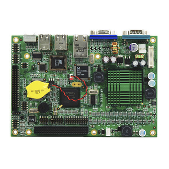
AR-B1631ET User’s Guide SYSTEM SETUP This chapter describes how to install the AR-B1631ET. At first, the layout of the AR-B1631ET is shown, and the unpacking information is described. 2.1 AR-B1631ET OVERVIEW PC104+ LX800 CS5536 W83627HG BIOS RTL8100C TOP VIEW SODIMM... -
Page 8: System Settings
Press the jumper evenly onto the pins. Be careful not to bend the pins. We will show the locations of the AR-B1631ET jumper pins, and the factory-default settings. CAUTION: Do not touch any electronic components unless you are safely grounded. Wear a grounded wrist strap or touch an exposed metal part of the system unit chassis. -
Page 9: Dio1 (Gpio)
AR-B1631ET User’s Guide 2.2.3 DIO1 (GPIO) XOUT0 XOUT1 XOUT2 XOUT3 XIN0 XIN1 XIN2 XIN3 2.2.4 AUDIO1 (AUDIO) LINE OUT R LINE OUT L LINE IN R LINE IN L MIC IN 2.2.5 COM2, COM3, COM4 (RS232) 2.2.6 J2 (CHASSIS CONTROL) +... -
Page 10: Ir1
AR-B1631ET User’s Guide 2.2.7 IRRX IRTX 2.2.8 J3 (CLEAR CMOS) NORMAL CLEAR CMOS 2.2.9 CN10 (LCD SETTING) -SHFCLK SHFCLK 3.3V LCD 5V LCD 2.2.10 CDIN1 (CDIN) CD_L CD_R 2.2.11 CN9 (POWER) +12V 2.2.12 CN8 (STAND BY POWER) +5V STANDBY PSON#... -
Page 11: J5 (Lcd Backlight)
AR-B1631ET User’s Guide 2.2.13 J5 (LCD BACKLIGHT) +12V +12V 2.2.14 JP4 (LCD LVDS) POWER LVDS_TXC+ LVDS_TXC- LVDS_TX2- LVDS_TX2+ LVDS_TX1+ LVDS_TX1- LVDS_TX0- LVDS_TX0+ LVDS_TX3- LVDS_TX3+ POWER POWER 2.2.15 LPT1 (PARALLEL PORT) STB- AFD- ERROR- INIT- SLIN- ACK- BUSY SELECT 11/30... -
Page 12: Buzzer External
AR-B1631ET User’s Guide 2.2.16 BUZZER EXTERNAL 2.2.17 J4 (PC104+) A1 B1 C1 D1 SERIRQ C/BE0# AD11 AD10 AD14 AD13 AD12 +3.3V C/BE1# AD15 +3.3V SERR# PULL UP PERR# +3.3V PULL UP STOP# +3.3V LOCK# +3.3V TRDY# DEVSEL# FRAME# IRDY# +3.3V AD16 +3.3V... -
Page 13: Jp6 (Ide Cable Select, Note 2)
AR-B1631ET User’s Guide 2.2.18 JP6 (IDE Cable Select, NOTE 2) Open ATA33 Close ATA66 above 2.2.19 USBA_1 & USBA_2 (NOTE 2) USB1- USB2- USB1+ USB2+ 2.2.20 USB1 & USB2 (NOTE 2) USB- USB+ USB- USB+ 2.2.21 JRS1 RS422 RS485 RS232... -
Page 14: Cn4 (Rs422 & Rs485)
AR-B1631ET User’s Guide 2.2.22 CN4 (RS422 & RS485) 1 RS422TX+/RS485TRX+ RS422TX-/RS485TRX- RS422RX+ RS422RX- 2.2.22 CF1 (NOTE 1) NOTE 1: For using both Hard Disk and Compact Flash, you have to use the ATA33 IDE cable. IF you want to use the ATA66/100 mode with the Hard Disk, you must put the jumper on JP6 and use the special IDE cable. -
Page 15: Lcd Flat Panel Display
AR-B1631ET User’s Guide LCD FLAT PANEL DISPLAY This chapter describes the configuration and installation procedures for LCD displays. LVDS1 Panel AR-B1631E Backlight connect to J5 Backlight Power Inverter LCD Panel Block Diagram Please visit our web site or contact our technical support department for supports of LCD connecting. -
Page 16: Bios Console
AR-B1631ET User’s Guide BIOS CONSOLE This chapter describes the AR-B1631ET BIOS menu displays and explains how to perform common tasks needed to get up and running, and presents detailed explanations of the elements found in each of the BIOS menus. The following topics are covered:... -
Page 17: Advanced
AR-B1631ET User’s Guide Date & Time Setup Highlight the <Date> field and then press the [Page Up] / [Page Down] or [+]/[-] keys to set the current date. Follow the month, day and year format. Highlight the <Time> field and then press the [Page Up] / [Page Down] or [+]/[-] keys to set the current date. -
Page 18: Power
AR-B1631ET User’s Guide Video Memory Size [8M] Configuration options: [None] [8M] [16M] [32M] [64M] [128M] [254M] Output Display [CRT] This allows you to choose the output of your system display. Configuration options: [CRT] [Flat Panel] [Panel +CRT] Flat Panel Type [Auto]... -
Page 19: Peripherals
AR-B1631ET User’s Guide PnP/PCI Reset Configuration Data [Disable] Normally, you leave this field Disabled. Select Enabled to reset the Extended System Configuration Data (ESCD) when you exit the Setup if you have installed a new add-on and the system reconfiguration has caused such a serious conflict that the operating system cannot boot. - Page 20 AR-B1631ET User’s Guide Onboard Serial Port 1 [3F8/IRQ4] Choose the serial port 1 I/O address. Do not set port 1, 2, 3 and 4 to the same address except for Disabled or Auto. Onboard Serial Port 2 [2F8/IRQ3] Choose the serial port 2 I/O address. Do not set port 1, 2, 3 and 4 to the same address except for Disabled or Auto.
-
Page 21: Boot
AR-B1631ET User’s Guide OnChip IDE Device With this option you can enable or disable your IDE channel and set the PIO mode or UDMA mode. 4.6 BOOT BOOT First/Second/Third Boot Device HDD-0 SCSI CDROM HDD-1 USB-FDD USB-ZIP USB-CDROM USB-HDD Disabled Boot Other Device [Enabled] Configuration options: [Enabled] [Disabled]. -
Page 22: Bios Exit
AR-B1631ET User’s Guide 4.7 BIOS EXIT Exit When you have made all of your selections from the various menus in the Setup program, save your changes and exit Setup. Select Exit from the menu bar to display the following menu. -
Page 23: O Address, Irq And Memory Mapping
AR-B1631ET User’s Guide I/O ADDRESS, IRQ AND MEMORY MAPPING 5.1 I/O ADDRESS MAPPING 23/30... -
Page 24: Irq Mapping
AR-B1631ET User’s Guide 5.2 IRQ MAPPING 5.3 MEMORY MAPPING 24/30... -
Page 25: Gpio Sample Code
AR-B1631ET User’s Guide GPIO SAMPLE CODE /*[]=====================================================================[]*/ /*|| GPIO Test utility for W83627HF. ||*/ /*|| Date : 10/18/2005 ||*/ /*|| Author : Willy ||*/ /*[]=====================================================================[]*/ /*[]=====================================================================[]*/ /*|| Include files ||*/ /*[]=====================================================================[]*/ #include <conio.h> #include <stdio.h> /*[]=====================================================================[]*/ /*|| Assember Types Define... - Page 26 AR-B1631ET User’s Guide /////// Input High Test /////////////////////////////////////////////////// printf("\nConnect GPI Pins to High ? [Y/N] .."); if(YES_NO_Confirm() =='n') { printf("\n>>>>> GPI Test Error <<<<<\n"); return 1; } // return fail Show_Byte=0x00; // Read W83627HF GPIO10~17 Status outportb(IO_PORT_BASE,0xF1); Read_Byte=inportb(IO_PORT_BASE+1); if(Read_Byte&0x01) //GPI10 Show_Byte=Show_Byte|0x01;...
- Page 27 AR-B1631ET User’s Guide Show_Byte=Show_Byte|0x40; else Show_Byte=Show_Byte&0xBF; if(Read_Byte&0x80) //GPI17 Show_Byte=Show_Byte|0x80; else Show_Byte=Show_Byte&0x7F; if(Show_Byte==0x00) printf("\nGPI Pins input value ==> 0x%002X",Show_Byte); else { printf("\nGPI Pins input value ==> 0x%002X (should be 0x00)",Show_Byte); printf("\n>>>>> GPI Test Error <<<<<\n"); return 1; } // return fail printf("\n>>>>>...
- Page 28 AR-B1631ET User’s Guide int main(int argc, char *argv[]) BYTE IO_PORT_BASE=0x2E; // DATA_PORT = IO_PORT_BASE + 1; int result; if ( argc != 2 ) { Show_Title(); return 1; } clrscr(); // Enter W83627HF Config Enter_Config(IO_PORT_BASE); Init_SIO(IO_PORT_BASE); switch(argv[1][0]) case 'i': case 'I': //I Key result=GPI_TEST(IO_PORT_BASE);...
- Page 29 AR-B1631ET User’s Guide /*|| Description: Confirm get 'Y' or 'N' key. ||*/ /*[]=====================================================================[]*/ char YES_NO_Confirm() int X_Axis,Y_Axis; char y_n; X_Axis=wherex(); /* Get Cursor X Axis */ Y_Axis=wherey(); /* Get Cursor Y Axis */ while(1) { y_n=getche(); if(y_n=='y' || y_n=='Y') return('y');...
- Page 30 AR-B1631ET User’s Guide void Enter_Config(BYTE IO_PORT_BASE) outportb(IO_PORT_BASE,0x87); outportb(IO_PORT_BASE,0x87); /*[]=====================================================================[]*/ /*|| Function : Exit_Config() ||*/ /*|| Input : BYTE IO_PORT_BASE ||*/ /*|| Change ||*/ /*|| Return : - ||*/ /*|| Description: Exit chip configuration key. ||*/ /*[]=====================================================================[]*/ void Exit_Config(BYTE IO_PORT_BASE) outportb(IO_PORT_BASE,0xAA);...
Need help?
Do you have a question about the AR-B1631ET and is the answer not in the manual?
Questions and answers