Table of Contents
Advertisement
Advertisement
Table of Contents

Related Manuals for Technogym Run XT


Summary of Contents for Technogym Run XT
- Page 1 & ERVICE MAINTENANCE MANUAL PRELIMINARY...
- Page 3 The information contained in this document is subject to change without notice. Technogym does not guarantee this documentation in any way. Technogym shall not be held responsible for any errors contained in this manual and declines all liability for accidents or damages resulting from the supply, characteristics or use of this manual.
-
Page 5: Table Of Contents
RUN XT: Service & Maintenance Manual - rev. 2.0 Contents 1. GENERAL NOTICES............................1.1 1.1. I ............................1.1 NTRODUCTION 1.2. R .............................1.1 ECOMMENDATIONS 1.3. G .....................1.2 ENERAL RULES FOR REPAIR PROCEDURES 2. TECHNICAL CHARACTERISTICS.......................2.1 2.1. M ........................2.1 ECHANICAL CHARACTERISTICS 2.2. E ........................2.1 LECTRICAL CHARACTERISTICS 2.3. - Page 6 RUN XT: Service & Maintenance Manual - rev. 2.0 7.2. D .........................7.2 ISASSEMBLING THE EPROM 7.3. D ........................7.3 ISASSEMBLING THE CPU BOARD 7.4. D ........................7.4 ISASSEMBLING THE KEYBOARD 7.5. D ......................7.5 ISASSEMBLING THE CARDIO RECEIVER 7.6. D ....................7.8 ISASSEMBLING THE EMERGENCY BUTTON 7.7.
- Page 7 RUN XT: Service & Maintenance Manual - rev. 2.0 11.1. T ....................11.1 ECHNICAL NOTES ON CARDIO RECEIVERS 11.1.1. type of ASIC..........................11.1 11.1.2. Presence of electromagnetic fields....................11.2 11.1.3. Reducing receiver sensitivity .......................11.2 11.1.4. Mechanical vibrations .........................11.3 11.1.5. Position of the receiver........................11.3 11.1.6.
- Page 8 RUN XT: Service & Maintenance Manual - rev. 2.0 Page intentionally left blank Page iv...
-
Page 9: General Notices
1. GENERAL NOTICES 1.1. INTRODUCTION This document is reserved for Technogym Service technicians, and is intended to provide authorized personnel with the necessary information to correctly carry out repairs and maintenance. A thorough knowledge of the technical information contained in this manual is essential for completing the professional training of the operator. -
Page 10: General Rules For Repair Procedures
1. Always mark any parts or positions which may be confused with each other at the time of reassembly. 2. Use original Technogym spare parts and lubricants of the recommended brands. 3. Use special tools where specified. 4. Consult the technical circulars, which may contain more up-to-date information on adjustments and maintenance than those contained in this manual. -
Page 11: Technical Characteristics
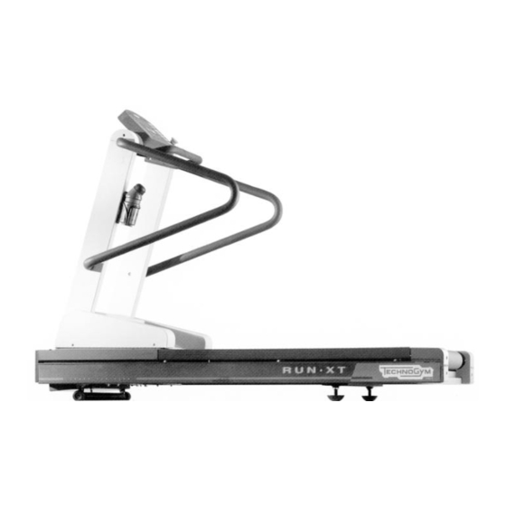
RUN XT: Service & Maintenance Manual - rev. 2.0 2. TECHNICAL CHARACTERISTICS 2.1. MECHANICAL CHARACTERISTICS Width 80 cm Length 190 cm Height 142 cm Weight 183 kg 2.2. ELECTRICAL CHARACTERISTICS There are two separate models of the machine for 220 and 110 V mains electricity supplies, which differ in certain components detailed in paragraph 2.7. -
Page 12: Wiring Diagram For The 220 Model
RUN XT: Service & Maintenance Manual - rev. 2.0 2.5. WIRING DIAGRAM FOR THE 220 MODEL 2.5.1. C ONNECTORS • CPU board name type of connector connection AMP MATE-N-LOCK 12-pin F. to up-down and inverter interface boards AMP MODU II 2-pin M. -
Page 13: Wiring
RUN XT: Service & Maintenance Manual - rev. 2.0 • Inverter interface board name type of connector connection AMP MATE-N-LOCK 6-pin F. to inverter AMP MATE-N-LOCK 12-pin F. to CPU board AMP MOD I 4-pin M to power supply • Up-down board... - Page 14 RUN XT: Service & Maintenance Manual - rev. 2.0 RX-13: Emergency button cable CPU – Emergency button CPU/CN2 Signal Color Emergency button NC contact Brown Reference Blue RX-5: Inverter cable Inverter interface board – Inverter – Motor thermal cutout Inverter interf.
- Page 15 RUN XT: Service & Maintenance Manual - rev. 2.0 RX-11: Up-down motor power supply cable Up-down board – Rectifier bridge Up-down board Signal Color Rectifier bridge 48 Vac − Ground Black RX-12: Photocell cable Up-down board – Photocell Up-down Signal...
-
Page 16: Wiring Diagram For The 220 Usa Model
RUN XT: Service & Maintenance Manual - rev. 2.0 2.6. WIRING DIAGRAM FOR THE 220 USA MODEL The differences between the 220 USA Model and the 220 Model are: • power supply cable; • high voltage wiring; • use of separate filters for the inverter and the power supply - up-down board;... - Page 17 RUN XT: Service & Maintenance Manual - rev. 2.0 RX-13 USA: Emergency cable CPU – Emergency button – Safety switch reed relay CPU/CN2 Signal Color Emergency Safety button reed relay NC contact Brown NC contact Blue Reference Orange OBSERVE: An upgrade kit is available (code 0WK247) for installing the safety switch on European machines.
-
Page 18: Wiring Diagram For The 110 Model
RUN XT: Service & Maintenance Manual - rev. 2.0 2.7. WIRING DIAGRAM FOR THE 110 MODEL The differences between the 110 Model and the 220 Model are: • the automatic circuit breaker is 20 A - class D instead of 10 A - class C;... -
Page 19: Principles Of Operation
RUN XT: Service & Maintenance Manual - rev. 2.0 3. PRINCIPLES OF OPERATION 3.1. BLOCK DIAGRAM The machine block diagram is shown in the figure below: CARDIO TRANSMITTER It is worn by the person using the machine, and transmits to the cardio receiver one pulse for every heart beat that is detected. - Page 20 RUN XT: Service & Maintenance Manual - rev. 2.0 (produced by high voltage lines, radio transmitters, monitors, motors, etc.) within its reception area, the receiver becomes saturated and stops receiving any signal. If there are 2 transmitters within its area of reception, it will receive signals from both, and may produce an error or irregular reading.
- Page 21 RUN XT: Service & Maintenance Manual - rev. 2.0 UP-DOWN MOTOR It is a DC motor which, by means of a mechanical reduction unit and a timing belt, turns the lead screw nuts on the threaded elevation bars, causing the machine to be raised or lowered depending on the direction of rotation.
-
Page 22: Tread-Belt Motor Drive
RUN XT: Service & Maintenance Manual - rev. 2.0 3.2. TREAD-BELT MOTOR DRIVE The tread belt is actuated by the motor through a linkage consisting of the motor pulley, the driving roller and the belt which connects them. In this way, a given belt motor speed corresponds to a predetermined linear tread belt speed. - Page 23 RUN XT: Service & Maintenance Manual - rev. 2.0 CN1 on the inverter interface board). The signal input to the inverter increases with increasing speed. The relationship between the speed reference and the inverter frequency is determined by the programming of the inverter.
-
Page 24: Up-Down Motor Drive
RUN XT: Service & Maintenance Manual - rev. 2.0 3.3. UP-DOWN MOTOR DRIVE The elevation of the machine is varied by the up-down motor which, by means of a timing belt, turns the lead screw nuts on the 2 elevation bars. The motor has an integral encoder wheel which, by means of a photocell, provides the motor motion control signal: each motor revolution corresponds to a predetermined number of pulses and to a predetermined displacement on the elevation bars. - Page 25 RUN XT: Service & Maintenance Manual - rev. 2.0 whether to keep the Up or Down signal asserted to continue the movement or, if the desired elevation has been reached, to reset the Up or Down signal. If, after having asserted the Up or Down signal, the CPU board does not receive any Status signal within a predetermined period of time (a few seconds), it resets the asserted signal and displays error code E5 to indicate absence of movement.
- Page 26 RUN XT: Service & Maintenance Manual - rev. 2.0 Page intentionally left blank Page 3.8...
-
Page 27: Accessories
4. ACCESSORIES 4.1. CONNECTING TO THE TGS The machine can be connected to the Technogym System by means of the 9-pin D-type connector situated on the back of the display, which provides the RS 232 serial port for connecting the TGS reader. - Page 28 RUN XT: Service & Maintenance Manual - rev. 2.0 Page intentionally left blank Page 4.2...
-
Page 29: Installation Instructions
RUN XT: Service & Maintenance Manual - rev. 2.0 5. INSTALLATION INSTRUCTIONS 5.1. SPECIFICATIONS AND REQUIREMENTS For correct machine installation, make sure that: 1. The machine is installed on a level surface that is free of vibrations and has sufficient carrying capacity for the combined weight of the machine and user. -
Page 30: First Power On
RUN XT: Service & Maintenance Manual - rev. 2.0 5.3. FIRST POWER-ON After completing the installation procedure, the machine is ready to be powered up. To turn on the machine, simply toggle the on/off switch from the 0 position to the 1 position. -
Page 31: Troubleshooting
RUN XT: Service & Maintenance Manual - rev. 2.0 6. TROUBLESHOOTING The troubleshooting procedures are shown in the form of flow charts. In order to facilitate consultation, the following standard box shapes are used. This type of box is the START point of the troubleshooting procedure. It typically contains a description of the problem or malfunction. -
Page 32: The Display Does Not Illuminate
RUN XT: Service & Maintenance Manual - rev. 2.0 6.1. THE DISPLAY DOES NOT ILLUMINATE THE DISPLAY DOES NOT ILLUMINATE Is the fuse OK? Replace the blown fuse Is mains lead OK? Replace the mains lead Connect machine to a... - Page 33 RUN XT: Service & Maintenance Manual - rev. 2.0 Replace the power Are DC voltages output by the supply: see paragraph power supply correct? 7.12. Replace the display Do all DC voltages reach the CPU board: see display? paragraph 7.3.
- Page 34 RUN XT: Service & Maintenance Manual - rev. 2.0 Is the mains voltage present at Replace the power the output of the power input input socket of the socket? machine Replace the cable connecting the input Is the mains voltage present at...
- Page 35 RUN XT: Service & Maintenance Manual - rev. 2.0 Follow the procedure step by step to correctly diagnose the problem. Take particular care with the checks highlighted by circled numbers, which are described in detail below: WARNING: Carry out these checks with the machine powered up.
-
Page 36: The Display Shows "E1" Or "E2
RUN XT: Service & Maintenance Manual - rev. 2.0 6.2. THE DISPLAY SHOWS “E1” OR “E2” These messages are related to the emergency button. The machine displays: • E1 if the emergency button is pressed during a training session. • E2 if the emergency button is pressed at the start of a training session. - Page 37 RUN XT: Service & Maintenance Manual - rev. 2.0 The SW version must be higher than EUR 2.4, USA 2.3, TGS EUR 2.2 or TGS USA 2.3. Place the tester probes between the terminals of the emergency button. When the button is pressed the measured voltage should be +5Vdc, when it is released it should be 0 Vdc.
-
Page 38: The Display Shows "E3" Or "E4
RUN XT: Service & Maintenance Manual - rev. 2.0 6.3. THE DISPLAY SHOWS “E3” OR “E4” These messages are related to the belt motor group. The machine displays: • E3 failure to actuate movement of the belt motor at the start of the training session;... -
Page 39: The Inverter Display Shows E1, E2, E3, E4 Or E5
RUN XT: Service & Maintenance Manual - rev. 2.0 6.3.1. T E1, E2, E3, E4 HE INVERTER DISPLAY SHOWS These inverter error messages are related to output short-circuit problems. Is the inverter output Replace the inverter: see short-circuited? paragraph 7.13. - Page 40 RUN XT: Service & Maintenance Manual - rev. 2.0 Place the tester probes between the blue - black, blue - brown and black - brown wires of the motor cable. The measured resistance should be approximately 3.1 Ohm. Disconnect the motor cable from the motor and place a tester between its terminals U-V, U-W and V-W.
- Page 41 RUN XT: Service & Maintenance Manual - rev. 2.0 6.3.2. T HE INVERTER DISPLAY SHOWS These inverter error messages are related to problems with the inverter braking group or the braking resistor. Is the braking resistor correctly connected to the...
-
Page 42: The Inverter Display Shows E6 Or E7
RUN XT: Service & Maintenance Manual - rev. 2.0 6.3.3. T E8, E10 HE INVERTER DISPLAY SHOWS These inverter error messages are related to HW and SW problems with the inverter. Does the error occur Replace the inverter: see frequently? paragraph 7.13. - Page 43 RUN XT: Service & Maintenance Manual - rev. 2.0 Determine the frequency of the errors by counting the number of occurrences in the inverter error memory, and by running targeted checks. An error is considered frequent if it occurs 2 or 3 times a day.
-
Page 44: The Inverter Display Shows E9
RUN XT: Service & Maintenance Manual - rev. 2.0 6.3.4. T HE INVERTER DISPLAY SHOWS This inverter error message is related to low line voltage problems on the inverter power supply. Does the machine resume Probable low line voltage. correct operation after being... - Page 45 RUN XT: Service & Maintenance Manual - rev. 2.0 Disconnect the filter power supply cables and place the tester probes on the terminals. The measured voltage should be 220 Vac or 110 Vac depending on the type of mains electricity supply.
-
Page 46: The Inverter Display Shows E12
RUN XT: Service & Maintenance Manual - rev. 2.0 6.3.5. T HE INVERTER DISPLAY SHOWS This inverter error message is related to the opening of the motor thermal cutouts. Does the machine resume Probable overheating of correct operation after being the motor. - Page 47 RUN XT: Service & Maintenance Manual - rev. 2.0 6.3.6. T HE INVERTER DISPLAY SHOWS This inverter error message is related to poor isolation between the motor phases and ground. Are the motor phases Replace the inverter: see isolated from ground at the paragraph 7.13...
-
Page 48: The Inverter Display Does Not Show Any Error
RUN XT: Service & Maintenance Manual - rev. 2.0 6.3.7. T HE INVERTER DISPLAY DOES NOT SHOW ANY ERROR This is an anomalous error condition in which the machine display reports an error but the inverter has not generated an error. - Page 49 RUN XT: Service & Maintenance Manual - rev. 2.0 Follow the procedure step by step to correctly diagnose the problem. Take particular care with the checks highlighted by circled numbers, which are described in detail below: The SW version must be higher than EUR 2.4, USA 2.3, TGS EUR 2.2 or TGS USA 2.3.
-
Page 50: The Belt Motor Is Jerking
RUN XT: Service & Maintenance Manual - rev. 2.0 6.4. THE BELT MOTOR IS JERKING THE BELT MOTOR IS JERKING Are the belt motor windings Replace the belt motor: short-circuited or open-circuited see paragraph 7.11. Does the inverter generate a... -
Page 51: The Belt Motor Starts With Delay
RUN XT: Service & Maintenance Manual - rev. 2.0 6.5. THE BELT MOTOR STARTS WITH DELAY THE BELT MOTOR STARTS WITH DELAY Are the Start and Speed PWM Replace the CPU board: signals correct at the output of the see paragraph 7.3. - Page 52 RUN XT: Service & Maintenance Manual - rev. 2.0 (ground) of connector CN1 on the inverter interface board. When the belt is halted the measured value should be 0 Vdc, whereas immediately after pressing the “Start” key on the display the reading should rapidly increase to reach a fixed value corresponding to the selected speed.
-
Page 53: The Displayed Speed Is Incorrect
RUN XT: Service & Maintenance Manual - rev. 2.0 6.6. THE DISPLAYED SPEED IS INCORRECT THE DISPLAYED SPEED IS INCORRECT Is the relationship between the The machine is operating displayed speed and the inverter correctly frequency correct? Replace the inverter: see paragraph 7.13. - Page 54 RUN XT: Service & Maintenance Manual - rev. 2.0 Check and/or replace Is the inverter control PWM signal at cable RX-1 connecting the output of the CPU board correct? the CPU board and the inverter interface board Replace the CPU board: see paragraph 7.3.
- Page 55 RUN XT: Service & Maintenance Manual - rev. 2.0 • For versions with the speed expressed in mph: SPEED PWM SIGNAL ANALOG SIGNAL FREQUENCY (mph) (Vdc) (Vdc) (Hz) CPU BOARD INVERTER INVERTER INTERFACE BOARD DISPLAY 6-3/CN1 10-3/CN2 5-6/CN1 DISPLAY 4.56 4.56...
-
Page 56: The Display Shows "E5
RUN XT: Service & Maintenance Manual - rev. 2.0 6.7. THE DISPLAY SHOWS “E5” THE DISPLAY SHOWS "E5" Are LEDs DL1 and DL2 on the up-down board both illuminated? Is the supply to the up-down motor correct when the actuation command... - Page 57 RUN XT: Service & Maintenance Manual - rev. 2.0 Is fuse F1 of the up-down board OK? Replace the fuse Check and/or replace the Does the up-down board receive the cable connecting the mains electricity supply? up-down board to the...
- Page 58 RUN XT: Service & Maintenance Manual - rev. 2.0 Lubricate the elevation bars Is the up-down motor current Are the elevation bars lubricated? correct? Replace the up-down motor: see paragraph 7.15. Is the pulse signal at the photocell Replace the photocell: see output correct? paragraph 7.20.
- Page 59 RUN XT: Service & Maintenance Manual - rev. 2.0 Follow the procedure step by step to correctly diagnose the problem. In particular, carry out the checks described in the flowchart with the machine at an elevation between 0 and +15%.
- Page 60 RUN XT: Service & Maintenance Manual - rev. 2.0 Slightly lift the connector on the photocell and place the tester probes between pins 4 (ground) and 2 (signal). When the motor moves, the tester should detect the pulses generated by the photocell.
-
Page 61: The Up-Down Moves In Only One Direction
RUN XT: Service & Maintenance Manual - rev. 2.0 6.8. THE UP-DOWN MOVES IN ONLY ONE DIRECTION THE UP-DOWN MOVES IN ONLY ONE DIRECTION Are LEDs DL1 and DL3 on the up-down board both illuminated? Is the machine in one of the 2 travel... - Page 62 RUN XT: Service & Maintenance Manual - rev. 2.0 Check the position and/or Is the limit switch associated with the replace the limit switch: non-illuminated LED tripped? see paragraph 7.19. Is the power supply to the limit Replace the limit switch: switch associated with the see paragraph 7.19.
- Page 63 RUN XT: Service & Maintenance Manual - rev. 2.0 If the machine fails to move downward, place the tester probes between pins 12 (ground) and 11 (signal) of connector CN1 on the CPU board: the measured voltage should be approximately 5 Vdc. If the machine fails to move upward, place the tester probes between pins 12 (ground) and 10 (signal) of connector CN1 on the CPU board: the measured voltage should be approximately 5 Vdc.
-
Page 64: The Displayed Elevation Is Incorrect
RUN XT: Service & Maintenance Manual - rev. 2.0 6.9. THE DISPLAYED ELEVATION IS INCORRECT THE DISPLAYED ELEVATION IS INCORRECT Is the position of the limit switch Adjust the position of the correct? limit switch Lubricate the elevation bars Is the up-down motor current... -
Page 65: There Is No Heart Rate Signal
RUN XT: Service & Maintenance Manual - rev. 2.0 6.10. THERE IS NO HEART RATE SIGNAL THERE IS NO CARDIO SIGNAL Is the supply voltage on the Replace the receiver: see receiver connector correct? paragraph 7.5. Is the supply voltage on... -
Page 66: The Heart Rate Signal Is Incorrect
RUN XT: Service & Maintenance Manual - rev. 2.0 6.11. THE HEART RATE SIGNAL IS INCORRECT In some case the machine may show “Err” on the heart rate display. THE HEART RATE SIGNAL IS INCORRECT Move the machines to Is the minimum distance... - Page 67 RUN XT: Service & Maintenance Manual - rev. 2.0 Is the transmitter in good Use a known good working order? transmitter Is the transmitter always Keep the transmitter within a distance of 80 cm within the minimum from the receiver? reception distance Change the receiver.
- Page 68 RUN XT: Service & Maintenance Manual - rev. 2.0 Page intentionally left blank Page 6.38...
-
Page 69: Disassembly Of Components
RUN XT: Service & Maintenance Manual - rev. 2.0 7. DISASSEMBLY OF COMPONENTS 7.1. DISASSEMBLING THE DISPLAY 1. Turn off the machine and unplug the mains lead from the wall outlet. 2. Remove the 2 caps a. 3. Unscrew the 6 self-tapping screws b which fix the DISPLAY, using a large Phillips screwdriver. -
Page 70: Disassembling The Eprom
RUN XT: Service & Maintenance Manual - rev. 2.0 7.2. DISASSEMBLING THE EPROM Carry out the procedure described in paragraph 7.1. “Disassembling the display”. With the display on a work bench: Remove EPROM a from its socket using an integrated-circuit extractor tool. -
Page 71: Disassembling The Cpu Board
RUN XT: Service & Maintenance Manual - rev. 2.0 7.3. DISASSEMBLING THE CPU BOARD Carry out the procedures described in paragraph 7.1. “Disassembling the display”. With the display placed on a work bench: 1. Disconnect keyboard connector a. 2. Remove the 5 screws b, using a small Phillips screwdriver. -
Page 72: Disassembling The Keyboard
RUN XT: Service & Maintenance Manual - rev. 2.0 7.4. DISASSEMBLING THE KEYBOARD Carry out the procedure described in paragraph 7.1. “Disassembling the display”. 1. Disconnect KEYBOARD connector a. Figure 7.4-1 With the display placed on a work bench: 1. Use a sharp tool to lift up a corner of the KEYBOARD and detach it. -
Page 73: Disassembling The Cardio Receiver
RUN XT: Service & Maintenance Manual - rev. 2.0 7.5. DISASSEMBLING THE CARDIO RECEIVER Version A: receiver positioned under the display. 1. Place the machine in its maximum elevation position. 2. Turn off the machine and unplug the mains lead from the wall outlet. - Page 74 RUN XT: Service & Maintenance Manual - rev. 2.0 Version B: receiver positioned inside the display, secured by a strap. Carry out the procedure described in paragraph 7.1. “Disassembling the display”. With the display on a work bench: 1. Cut the fixing strap e.
- Page 75 RUN XT: Service & Maintenance Manual - rev. 2.0 Version C: receiver housed in a box inside the display. Carry out the procedure described in paragraph 7.1. “Disassembling the display”. With the display on a work bench: 1. Unscrew the screws i on RECEIVER housing box l using a small Phillips screwdriver.
-
Page 76: Disassembling The Emergency Button
RUN XT: Service & Maintenance Manual - rev. 2.0 7.6. DISASSEMBLING THE EMERGENCY BUTTON 1. Turn off the machine and unplug the mains lead from the wall outlet. 2. Unscrew the 8 self-tapping screws a which fix the DISPLAY, using a large Phillips screwdriver. - Page 77 RUN XT: Service & Maintenance Manual - rev. 2.0 5. Back off the 2 screws c which fix the EMERGENCY BUTTON to the panel using a large Phillips screwdriver. Figure 7.6-3 6. Firmly gripping the inner part, push and rotate the EMERGENCY BUTTON to detach it.
-
Page 78: Disassembling The Motor Guard
RUN XT: Service & Maintenance Manual - rev. 2.0 7.7. DISASSEMBLING THE MOTOR GUARD 1. Turn off the machine and unplug the mains lead from the wall outlet. 2. Unscrew the 6 screws a using a large Phillips screwdriver. 3. Remove the MOTOR GUARD b. -
Page 79: Disassembling The Front Plate
RUN XT: Service & Maintenance Manual - rev. 2.0 7.8. DISASSEMBLING THE FRONT PLATE 1. Carry out the procedure described in paragraph 7.7. “Disassembling the motor guard”. 2. Unscrew the 4 self-tapping screws a using a large Phillips screwdriver. 3. Rotate the FRONT PLATE b downward. -
Page 80: Disassembling The Running Track
RUN XT: Service & Maintenance Manual - rev. 2.0 7.9. DISASSEMBLING THE RUNNING TRACK 1. Turn off the machine and unplug the mains lead from the wall outlet. 2. Unscrew the 2 screws a using a 6-mm Allen T wrench. - Page 81 RUN XT: Service & Maintenance Manual - rev. 2.0 6. Depending on the type of shock absorbers: • Unscrew the 6 screws d using a 5-mm Allen T wrench. • Unscrew the 2 rear screws d using a 5- mm Allen T wrench, and the 4 front...
-
Page 82: Disassembling The Driven Roller, The Driving Roller, The Tread Belt And The Motor Belt
RUN XT: Service & Maintenance Manual - rev. 2.0 7.10. DISASSEMBLING THE DRIVEN ROLLER, THE DRIVING ROLLER, THE TREAD BELT AND THE MOTOR BELT 1. Place the machine in the maximum elevation position. 2. Carry out the procedure described in paragraphs 7.7. - Page 83 RUN XT: Service & Maintenance Manual - rev. 2.0 9. Move the belt motor toward the DRIVING ROLLER g and pull outward to remove belt h from the motor pulley i. Figure 7.10-4 10. Unscrew the 2 fixing screws of the DRIVING ROLLER l using a 6-mm Allen T wrench.
- Page 84 RUN XT: Service & Maintenance Manual - rev. 2.0 To reassemble the DRIVEN ROLLER, the DRIVING ROLLER, the TREAD BELT and the MOTOR BELT, carry out the above steps in reverse order. To ensure correct reassembly, insert the DRIVING ROLLER in the MOTOR BELT before assembling it on the supports.
-
Page 85: Disassembling The Belt Motor
RUN XT: Service & Maintenance Manual - rev. 2.0 7.11. DISASSEMBLING THE BELT MOTOR 1. Carry out the procedure described in paragraph 7.7. “Disassembling the motor ”. 2. Remove the dust guard. 3. Unscrew the 4 nuts a (2 are concealed by the... - Page 86 RUN XT: Service & Maintenance Manual - rev. 2.0 10. Disconnect the 3 phase conductors f using a 7-mm wrench, the ground conductor g using a large Phillips screwdriver, and the motor thermal cutout h using a small flat-blade screwdriver.
-
Page 87: Disassembling The Electronic Circuit Boards
RUN XT: Service & Maintenance Manual - rev. 2.0 7.12. DISASSEMBLING THE ELECTRONIC CIRCUIT BOARDS 1. Carry out the procedures described in paragraphs 7.7. “Disassembling the motor guard” and 7.8. “Disassembling the front plate”. 2. Cut any straps fixing the cables to the grille protecting the ELECTRONIC CIRCUIT BOARDS. -
Page 88: Disassembling The Inverter
RUN XT: Service & Maintenance Manual - rev. 2.0 7.13. DISASSEMBLING THE INVERTER 1. Carry out the procedure described in paragraph 7.7. “Disassembling the motor guard”. 2. Remove the INVERTER cover, using a small Phillips screwdriver to unscrew the fixing screw, if present. -
Page 89: Disassembling The Up-Down Motor Belt
RUN XT: Service & Maintenance Manual - rev. 2.0 7.14. DISASSEMBLING THE UP-DOWN MOTOR BELT 1. Place the machine in its maximum elevation position. 2. Carry out the procedures described in paragraphs 7.7. “Disassembling the motor guard” and 7.8. “Disassembling the front plate”. -
Page 90: Disassembling The Up-Down Motor
RUN XT: Service & Maintenance Manual - rev. 2.0 7.15. DISASSEMBLING THE UP-DOWN MOTOR 1. Carry out the procedure described in paragraph 7.14. “Disassembling the up-down motor belt” up to the slackening of the belt (step 7). 2. Disconnect the motor power supply cable and the photocell cable. - Page 91 RUN XT: Service & Maintenance Manual - rev. 2.0 8. Strike the motor shaft with a rubber hammer, and, using a pointed tool if necessary, remove the shaft from the lower side of the machine. Figure 7.15-3 9. Recover the tab d.
- Page 92 RUN XT: Service & Maintenance Manual - rev. 2.0 10. Disassemble protective housing encoder wheel, using, depending on the type of motor: • “BONFIGLIOLI” motor: 10-mm wrench; • “SITI” motor: 8-mm wrench. 11. Unscrew the 4 fixing screws of the UP-...
-
Page 93: Disassembling The Up Down Motor Brushes
RUN XT: Service & Maintenance Manual - rev. 2.0 7.16. DISASSEMBLING THE UP-DOWN MOTOR BRUSHES It is not possible to carry out this procedure on all types of motors. 1. Carry out the procedures described in paragraphs 7.7. “Disassembling the motor guard”... -
Page 94: Disassembling The Elevation Bars
RUN XT: Service & Maintenance Manual - rev. 2.0 7.17. DISASSEMBLING THE ELEVATION BARS 1. Place the machine in its maximum elevation position. 2. Carry out the operations described in paragraphs 7.7. “Disassembling the motor guard” and 7.8. “Disassembling the front plate”. -
Page 95: Disassembling The Lead Screw Nuts
RUN XT: Service & Maintenance Manual - rev. 2.0 7.18. DISASSEMBLING THE LEAD SCREW NUTS 1. Place the machine in its maximum elevation position. 2. Carry out the procedures described in paragraphs 7.7. “Disassembling the motor guard” and 7.8. “Disassembling the front plate”. - Page 96 RUN XT: Service & Maintenance Manual - rev. 2.0 10. Remove the LEAD SCREW NUT GROUP. To reassemble the LEAD SCREW NUT GROUP, carry out the above steps in reverse order. Figure 7.18-3 Page 7.28...
-
Page 97: Disassembling The Limit Switches
RUN XT: Service & Maintenance Manual - rev. 2.0 7.19. DISASSEMBLING THE LIMIT SWITCHES 1. Carry out the procedures described in paragraphs 7.7. “Disassembling the motor guard” and 7.8. “Disassembling the front plate”. To remove the LIMIT SWITCHES: 2. Disconnect the cables a. -
Page 98: Disassembling The Photocell
RUN XT: Service & Maintenance Manual - rev. 2.0 7.20. DISASSEMBLING THE PHOTOCELL 1. Carry out the procedures described in paragraphs 7.7. “Disassembling the motor guard” and 7.8. “Disassembling the front plate”. 2. Disconnect connector a on the PHOTOCELL board. -
Page 99: Adjustments
RUN XT: Service & Maintenance Manual - rev. 2.0 8. ADJUSTMENTS 8.1. TENSIONING A NEW TREAD BELT 1. After assembling the new tread belt, tighten the tread belt until it is just slightly taut. 2. Place a tape measure along the right hand... -
Page 100: Tensioning A Used Tread Belt
RUN XT: Service & Maintenance Manual - rev. 2.0 8.2. TENSIONING A USED TREAD BELT 1. After completing reassembly of the used tread belt, lock down the rear right hand screw a until measurement L in Figure 8.2-2 corresponds to the value shown on the red decal b on the inside of the rear right hand cap. -
Page 101: Centering The Tread Belt
RUN XT: Service & Maintenance Manual - rev. 2.0 8.3. CENTERING THE TREAD BELT 1. Start the machine at a speed of 10 km/h. 2. Observe the movement of the tread belt, correcting any tendency to shift to the right or left exclusively by adjusting the left tensioning screw a. -
Page 102: Adjusting The Tension And Alignment Of The Tread-Belt Motor Belt
RUN XT: Service & Maintenance Manual - rev. 2.0 8.4. ADJUSTING THE TENSION AND ALIGNMENT OF THE TREAD-BELT MOTOR BELT 1. Carry out the procedures described in paragraphs 7.7. “Disassembling the motor guard” and 7.8. “Disassembling the front plate”. 2. Remove the dust guard. - Page 103 RUN XT: Service & Maintenance Manual - rev. 2.0 To adjust the alignment, use a straight-line reference rod d, rested against the driving roller pulley, and make sure that: • The pulley and flywheel are parallel. 1. Repeat steps 3 and 4.
-
Page 104: Tensioning The Up-Down Motor Belt
RUN XT: Service & Maintenance Manual - rev. 2.0 8.5. TENSIONING THE UP-DOWN MOTOR BELT 1. Carry out the procedures described in paragraphs 7.7. “Disassembling the motor guard” and 7.8. “Disassembling the front plate”. 2. Place the machine on its maximum elevation position. -
Page 105: Aligning The Elevation Bars
RUN XT: Service & Maintenance Manual - rev. 2.0 8.6. ALIGNING THE ELEVATION BARS 1. With the machine turned over on one side, turn one of the elevation bars until the wheel shaft holes on both bars are aligned. 2. Use a gauge to make sure that both elevation bars project by the same distance A from the lead screw nuts. -
Page 106: Calibrating The Tread Belt Speed
RUN XT: Service & Maintenance Manual - rev. 2.0 8.7. CALIBRATING THE TREAD BELT SPEED 1. Carry out the procedure described in paragraph 7.7. “Disassembling the motor guard. The operations described below must be carried out with the machine powered... -
Page 107: Centering The Photocell
RUN XT: Service & Maintenance Manual - rev. 2.0 8.8. CENTERING THE PHOTOCELL 1. Carry out the procedures described in paragraphs 7.7. “Disassembling the motor guard” and 7.8. “Disassembling the front plate”. 2. Using a 10-mm wrench, unscrew the 2 fixing screws of the cover of the protective housing of the encoder wheel, where present. - Page 108 RUN XT: Service & Maintenance Manual - rev. 2.0 Page intentionally left blank Page 8.10...
-
Page 109: Machine Configuration
RUN XT: Service & Maintenance Manual - rev. 2.0 9. MACHINE CONFIGURATION Starting from the release 3.0 of the SW, it is possible to set some configuration parameters of the machine. Not all CPU boards are compatible with SW release 3.0. Therefore, if after replacing the EPROM with the new one, the machine doesn’t start up, it means that in order to... -
Page 110: Maximum Time
RUN XT: Service & Maintenance Manual - rev. 2.0 and press ENTER to confirm your choice. 9.1.3. M AXIMUM TIME You can set the maximum time that can be programmed for each exercise. To change the current setting, when the maximum time is actually in use will scroll on the LED matrix, input the desired time using the numeric keys and press ENTER to confirm. -
Page 111: Maintenance Information
RUN XT: Service & Maintenance Manual - rev. 2.0 9.2. MAINTENANCE INFORMATION In order to perform regular maintenance correctly, the actual number of hours the equipment has been operated and turned on can be visualized by entering a special access code. With the equipment in the standby mode, press numeric keys 314 at the same time. -
Page 112: Hours Of Use
RUN XT: Service & Maintenance Manual - rev. 2.0 9.3.2. H OURS OF USE To change this value, when the value actually in memory will scroll on the LED matrix, input the desired value using the numeric keys to enter and press ENTER to confirm. Just press ENTER to maintain the original value. -
Page 113: Programming The Hitachi J100 Inverter
RUN XT: Service & Maintenance Manual - rev. 2.0 9.4. PROGRAMMING THE HITACHI J100 INVERTER 9.4.1. V ERSION Version E2 of the HITACHI J100 inverter can be programmed only by using the special external keyboard DRW 100 EA to copy the correct version of the EPROM program supplied by the manufacturer. - Page 114 RUN XT: Service & Maintenance Manual - rev. 2.0 4. To save the modified value, press the FUNC key: the display reverts to showing the value of the selected main function. To display the parameters of the extended functions: 1. Press the FUNC key until function F 14 appears.
- Page 115 RUN XT: Service & Maintenance Manual - rev. 2.0 EXTENDED FUNCTIONS FUNCTION Value Default FUNCTION Value Default A 37 A 38 A 39 A 40 A 41 A 42 A 43 A 48 A 49 A 50 A 10 A 51...
- Page 116 RUN XT: Service & Maintenance Manual - rev. 2.0 Page intentionally left blank Page 9.8...
-
Page 117: Scheduled Maintenance
RUN XT: Service & Maintenance Manual - rev. 2.0 10. SCHEDULED MAINTENANCE To keep the machine in perfect working order, carry out the scheduled maintenance operations set out in the table below: CLEANING TENSION WEAR FUNCTION LUBRI- CHECK CHECK CHECK... - Page 118 RUN XT: Service & Maintenance Manual - rev. 2.0 (B) INTERNAL CLEANING Carry out once a month. With the machine turned off, open the motor guard (see paragraph 7.7. ) use a vacuum cleaner or compressed air to clean the entire interior, paying particular attention to the dust filter, the belt motor and the inverter.
- Page 119 RUN XT: Service & Maintenance Manual - rev. 2.0 (L) UP-DOWN MOTOR BELT WEAR CHECK Carry out every 6 months. Place the machine in its maximum elevation position and turn it off. Remove the up-down motor belt guard (see paragraph 7.14. ) and check the state of wear of the up-down motor belt.
- Page 120 RUN XT: Service & Maintenance Manual - rev. 2.0 Page intentionally left blank Page 10.4...
-
Page 121: Appendix
RUN XT: Service & Maintenance Manual - rev. 2.0 11. APPENDIX 11.1. TECHNICAL NOTES ON CARDIO RECEIVERS The receiver shown in the figure below is equipped with: Figure 11.1-1 • an antenna a, designated the “coil”, which receives the signal from the transmitter strap worn by the user. -
Page 122: Presence Of Electromagnetic Fields
RUN XT: Service & Maintenance Manual - rev. 2.0 11.1.2. P RESENCE OF ELECTROMAGNETIC FIELDS The receiver is sensitive to electromagnetic fields produced by the switching of LEDs, motor brushes, the commutation of power devices, monitors, neon lights, stereo equipment, etc., which can impair its operation. -
Page 123: Mechanical Vibrations
RUN XT: Service & Maintenance Manual - rev. 2.0 • presence of electromagnetic fields which interfere with reception or saturate the receiver; • problems due to interaction between the receiver on one machine and the signal transmitted by a user training on another machine that is too close and cannot be moved farther away. - Page 124 RUN XT: Service & Maintenance Manual - rev. 2.0 • the coil must be directed toward the user; • the coil must be positioned well away (even a few centimeters) from the LEDs; • the cable must be folded immediately after the connection on the receiver, so that it does not pass near the coil;...
-
Page 125: Routing Of Cables
RUN XT: Service & Maintenance Manual - rev. 2.0 • Version with receiver inside the display: Figure 11.1-4 11.1.6. R OUTING OF CABLES Particular care must be taken in the routing of cables to prevent interference with the receiver coil. -
Page 126: Hitachi J100 Inverter Error Codes
RUN XT: Service & Maintenance Manual - rev. 2.0 11.2. HITACHI J100 INVERTER ERROR CODES The inverter memorizes all the errors detected during operation, in the form of a code which indicates the cause of the error. The table below lists the error codes and their meaning, as referred to in chapter 6. - Page 127 RUN XT: Service & Maintenance Manual - rev. 2.0 • The error code. • Current at the time of the error. • Voltage at the time of the error (this is the DC voltage internal to the inverter; to obtain the actual mains voltage simply divide this value by 0.14).
-
Page 128: Multimeter Measurements
RUN XT: Service & Maintenance Manual - rev. 2.0 11.3. MULTIMETER MEASUREMENTS 11.3.1. AC VOLTAGE To measure an AC VOLTAGE with a multimeter: 1. Select, where available, the AC voltage function which is generally indicated by the symbols: VAC, VAC~, V~;... -
Page 129: Ac And Dc Current
RUN XT: Service & Maintenance Manual - rev. 2.0 Remember to place the ground probe on the signal reference in order to obtain a measurement that has the same polarity as the signal. 11.3.3. AC CURRENT To measure either an AC or DC CURRENT using a multimeter: 1. - Page 130 RUN XT: Service & Maintenance Manual - rev. 2.0 Page intentionally left blank Page 11.10...
- Page 132 TECHNOGYM INDUSTRIE S.r.l. Via G. Perticari, 20 47035 Gambettola (Forlì ) ITALIA Tel.: +39 - 547 56047 Fax: +39 - 547 650 150 e-mail: service@technogym.com 0SMM0024-ING...
Need help?
Do you have a question about the Run XT and is the answer not in the manual?
Questions and answers