Table of Contents
Advertisement
Copyright
This publication, including all photographs, illustrations and software, is protected un-
der international copyright laws, with all rights reserved. Neither this manual, nor any
of the material contained herein, may be reproduced without written consent of the au-
thor.
Version 1.0La
Disclaimer
The information in this document is subject to change without notice. The manufac-
turer makes no representations or warranties with respect to the contents hereof and
specifically disclaims any implied warranties of merchantability or fitness for any par-
ticular purpose. The manufacturer reserves the right to revise this publication and to
make changes from time to time in the content hereof without obligation of the manu-
facturer to notify any person of such revision or changes.
Trademark Recognition
Microsoft, MS-DOS and Windows are registered trademarks of Microsoft Corp.
MMX, Pentium, Pentium-II, Pentium-III, Celeron are registered trademarks of Intel
Corporation.
Other product names used in this manual are the properties of their respective owners
and are acknowledged.
Federal Communications Commission (FCC)
This equipment has been tested and found to comply with the limits for a Class B digi-
tal device, pursuant to Part 15 of the FCC Rules. These limits are designed to provide
reasonable protection against harmful interference in a residential installation. This
equipment generates, uses, and can radiate radio frequency energy and, if not in-
stalled and used in accordance with the instructions, may cause harmful interference
to radio communications. However, there is no guarantee that interference will not oc-
cur in a particular installation. If this equipment does cause harmful interference to
radio or television reception, which can be determined by turning the equipment off
and on, the user is encouraged to try to correct the interference by one or more of the
following measures:
−
Reorient or relocate the receiving antenna.
−
Increase the separation between the equipment and the receiver.
−
Connect the equipment onto an outlet on a circuit different from that to which
the receiver is connected.
−
Consult the dealer or an experienced radio/TV technician for help.
Shielded interconnect cables and a shielded AC power cable must be employed with
this equipment to ensure compliance with the pertinent RF emission limits governing
this device. Changes or modifications not expressly approved by the system's manu-
facturer could void the user's authority to operate the equipment.
Preface
Advertisement
Table of Contents

Related Manuals for ECS kt600-a


Summary of Contents for ECS kt600-a
- Page 1 Preface Copyright This publication, including all photographs, illustrations and software, is protected un- der international copyright laws, with all rights reserved. Neither this manual, nor any of the material contained herein, may be reproduced without written consent of the au- thor.
-
Page 2: Declaration Of Conformity
Declaration of Conformity This device complies with part 15 of the FCC rules. Operation is subject to the follow- ing conditions: − This device may not cause harmful interference, and − This device must accept any interference received, including interference that may cause undesired operation. - Page 3 Features Translations Caractéristiques Processeur La carte mère utilise un Socket A AMD 462 broches présentant les caractéristiques suivantes: • Supporte un bus frontal (FSB) de 400/333/266/200 MHz • Peut recevoir les CPU AMD Athlon XP/Sempron/Athlon /Duron • Transfert DDR (Double Data Rate) 200/166/133 MHz sur adresse CPU AMD Athlon XP/Sempron/Athlon/Duron et bus de données Remarque : Il est conseillé...
- Page 4 Options La KT600-A offre quatre slots 32 bits PCI, un logement AGP d’Extensions (supportant seulement la carte AGP 1.5V) et logement CNR (Communications and Networking Riser). Elle supporte la maîtrise de bus Ultra DMA avec des vitesses de transfert de...
- Page 5 • Synchronisation de CPU et de mémoire Le microprogramme peut aussi être utilisé pour définir les paramètres pour les vitesses d’horloges de différents processeurs. Certaines spécifications matérielles et éléments de logiciels peuvent être modifiés sans avertissement.
- Page 6 Funktionen Prozessor Das Mainboard verwendet einen AMD 462-Pin Sockel A mit den folgenden Eigenschaften: • Unterstützt 400/333/266/200 MHz Frontsidebus (FSB) • Nimmt AMD Athlon XP/Sempron/Athlon/Duron -CPU auf. • 200/166/133 MHz DDR (Double Data Rate) Transfer auf AMD Athlon XP/Sempron/Athlon/Duron CPU-Adressen- und Datenbussen Hinweis: Die Verwendung einer CPU vom Typ AMD Athlon XP oder höher wird empfohlen, damit...
- Page 7 PC oder andere elektronische Geräte eine SPDIF-Out- Funktion. Weitere Funktionen beinhalten z.B. die Unterstützung von vier analogen Line-Level-Eingängen. Erweiterungs- Das KT600-A verfügt über vier 32-Bit PCI- Steckplätze, einen optionen AGP-Steckplatz (unterstützt nur 1.5V 4x AGP-Karte) und einen CNR (Communications and Networking Riser)-Steckplatz.
- Page 8 Caratteristiche Processore La scheda madre è dotata di un socket A AMD a 462 pin che presenta le seguenti caratteristiche: • Supporta il bus di sistema 400/333/266/200 MHz frontside (FSB) • Compatibile con CPU AMD Athlon XP/Sempron/Athlon/Duron • Trasferimento 200/166/133 MHz DDR (Double Data Rate) su i bus dati e indirizzo AMD Athlon XP/Sempron /Athlon/Duron CPU Note: Si raccomanda l’uso di una CPU AMD Athlon XP o...
- Page 9 Altre caratteristiche includono il supporto di quattro entrate LINE STEREO analogiche. Opzioni La KT600-A presenta di quattro porte PCI a 32 bit ed uno slot di espansione AGP (compatibile solamente con la scheda 4x AGP 1,5V) ed uno slot CNR (Communications and Networking Riser).
- Page 10 Características Procesador El panel principal usa un AMD 462-pin Enchufe A que tiene las siguientes características: • Permite 400/333/266/200 MHz bus de lado frontal (FSB) • Acomoda una CPU AMD Athlon XP/Sempron/Athlon/ Duron • Transferencia de 200/166/133 MHz DDR (Double Data Rate/Índice de Datos Doble) en dirección AMD Athlon XP/Sempron/Athlon/Duron CPU y buses de datos Nota: Se recomienda que usted use AMD Athlon XP u...
- Page 11 Otras características incluyen soporte para cuatro entradas estereofónicas a nivel de línea analógica. Opciones de El KT600-A provee cuatro ranuras PCI de 32-bit una ranura Expansión AGP (permite solo tarjeta 1.5V AGP) y ranura CNR (Comunicaciones y Contrahuella de Red).
- Page 12 製品特徴 プロセッサ 当メインボードは ADM 462 ピンソケットを搭載し、次の特長 があります: • 400/333/266/200 MHzフロントサイドバス(FSB)をサ ポートします • AMD Athlon XP/Sempron/Athlon/Duron CPU に対応 • AMD Athlon XP/Sempron/Athlon/Duron CPU のア ドレスバスとデータバスを 200/166/133 MHz DDR (Dou- ble Data Rate) の転送率でサポート。 メモ: "Termal Diode" 機能を正しく作動させるた めに、AMD Athlon XP またはそれ以上の CPU のご使用をお勧めします。...
- Page 13 1/10/100 MHz の全/半二重動作が可能。 • 最大 DDR266/333/400 までの DDR SDRAM メモリモジュー メモリー ル をサポート • 2 つの非バッファー2.5V184 ピン仕様のスロットを収納 • 各スロットはメモリーを 1 GB まで、トータルで 3GB まで サポートします。(DDR 400 の場合は、最大 2 GB まで) グラフィック 本マザーボードは、従来の AGP 仕様の 8 倍のバンド幅を提供す ることができる AGP スロットが含まれています。AGP3.0 (8xAGP) は、ワークステーションやデスクトップ環境におい て、より優れたグラフィックインターフェースのニーズに対応...
- Page 14 • Wake-up 警告 • CPU パラメータ • CPU およびメモリのタイミング その他に、各種プロセッサクロック速度のパラメータを設定 することができます。 一部のハードウェア仕様及びソフトウェアアイテムは予告なく変更されるこ とがあります。 기능 프로세서 이 메인보드는 AMD 462 핀 소켓 A 를 사용하며 다음과 같은...
- Page 15 특징을 지닌다: • 400/333/266/200 MHz frontside bus (FSB) 지원 • AMD Athlon XP/Sempron/Athlon/Duron CPU 를 사용한다. • AMD Athlon XP/Sempron/Athlon/Duron CPU 어드레스 및 데이터 버스에서의 200/166/133 MHz DDR (Double Data Rate) 전송 Note: “ 열 다이오드” 기능이 적절히 기능하도록 AMD Athlon XP 또는 그 이상의 CPU 사용을...
- Page 16 지원하여 PC 와 다른 전기 제품의 연결을 용이하게 한다. 그 밖에도 4 개의 아날로그 라인 레벨 스테레오 입력을 지원한다. 확장 옵션 KT600-A 는 4 개의 32-bit PCI 슬롯을 제공한다, 1 개의 AGP 슬롯 (1.5V AGP 카드만), CNR (Communications and Networking Riser) 슬롯이 있다.
- Page 17 處理器 本主機板採用了具有下列功能之 AMD 462 針 Socket A: • 支援高達 400/333/266/200 MHz 之系統匯流排(FSB) • 支援 AMD Athlon XP/Sempron/Athlon/Duron 處理器 • 支援高達 200/166/133MHz DDR (Double Data Rate, 雙倍速資 料傳輸) 之 AMD Athlon XP/Sempron/Athlon/Duron CPU 位址 和數據匯流排傳輸 註解: 建議使用 AMD Athlon XP 或更高等級之 CPU, 以確保過熱保護電路...
- Page 18 支援符合 AC’97 2.3 規格的 SPDIF 輸出功能,能夠使其他電子 產品更容易地與連接電腦連接。再者,也提供 4 種類比線級立 體音效輸入。 擴充選項 KT600-A 配備有 4 個 32 位元 PCI 插槽、1 個 AGP 插槽 (僅支援 1.5 伏特電壓規格之 AGP 卡) 及 CNR (Communications and Net- working Riser) 插槽。 此外,也支援 Ultra DMA 匯流排主控功能,可提供 33/66/100/ 133 MB/sec 之傳輸速率。...
- Page 19 特点: • 支持 400/333/266/200 MHz 前端总线 (FSB) • 支持 AMD Athlon XP/Sempron/Athlon/Duron CPU • AMD Athlon XP/Sempron/Athlon/Duron CPU 地址和 数据总线上 200/166/133 MHz DDR(双数据传输率)传输 说明: 建议您使用 AMD Athlon XP 或更高频率 的处理器,以确保能够正常使用“Thermal Diode”功能。 芯片组 此主板含有 KT600 北桥芯片组和 VT8237 南桥芯片组。下表中 简要介绍了芯片组的先进功能。 芯片组 功能 AMD Athlon XP/Sempron/Athlon/Duron CPU 地址...
- Page 20 的 SPDIF 输出功能,此功能可以方便的将 PC 与其它电子产品 连接在一起。其它功能包括支持 4 路模拟线路级立体声输入。 KT600-A 提供 4 个 32 位 PCI 插槽。1 个 AGP(仅支持 1.5V 扩展 选项 AGP 卡) 插槽和 1 个 CNR(通信网络转接卡)插槽。 它支持 Ultra DMA 总线控制,传输速率可达 33/66/100/133 MB/sec。 VT6103 是一种物理层设备,可用于使用 5 类非屏蔽线、1 类屏 Onboard LAN (可选)...
-
Page 21: Table Of Contents
Features Translations CHAPTER 1 Introducing the Motherboard Introduction ....................1 Features .....................2 Choosing a Computer Case ...............4 Motherboard Components ................5 CHAPTER 2 Installing the Motherboard Safety Precautions..................7 Quick Guide ....................7 Installing the Motherboard in a Case ............8 Checking Jumper Settings ................8 Setting Jumpers .................... - Page 22 Set Supervisor/User Password............... 48 Save & Exit Setup ..................49 Exit Without Saving ..................49 CHAPTER 4 Using the Motherboard Software About the Software CD-ROM ..............50 Auto-installing under Windows 98/ME/2000/XP ........50 Running Setup ....................51 Manual Installation..................53 Utility Software Reference ................53 xxii...
-
Page 23: Introducing The Motherboard
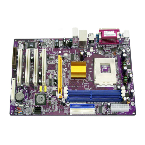
Introducing the Motherboard Thank you for choosing the KT600-A motherboard. The KT600-A is designed to fit the advanced AMD processors in the 462-pin package, supporting socket 462 AMD Athlon XP / Sempron / Athlon / Duron processors. Based on the ATX... -
Page 24: Features
Processor The motherboard uses an AMD 462-pin Socket A that has the following features: • Supports 400/333/266/200 MHz Front Side Bus (FSB) • Accommodates AMD Athlon XP/Sempron/Athlon/Duron • 200/166/133 MHz DDR (Double Data Rate) transfer on Ath- lon XP/Sempron/Athlon/Duron CPU and data buses Note: It is recommended that you use AMD Athlon XP or higher level CPU to make sure that the “Ther- mal Diode”... - Page 25 SPDIF out function which allows easy connection from the PC to other electronic products. Further features include support for four analog line-level stereo inputs. Expansion The KT600-A provides four 32-bit PCI slots, an AGP slot (sup- Options ports 1.5V AGP card only) and CNR (Communications and Networking Rise slot.
-
Page 26: Choosing A Computer Case
There are many types of computer cases on the market. The motherboard complies with the specifications for the ATX system case. Some features on the motherboard are implemented by cabling connectors on the motherboard to indicators and switches on the system case. Ensure that your case sup- ports all the features required. - Page 28 Table of Motherboard Components Label Component AGP1 Accelerated Graphics Port (supports 1.5V AGP card only) ATX1 Standard 20-pin ATX power connector AUDIO1 Front audio connector AUXIN1 Extra line-in connector BAT1 Three volt realtime clock battery CASFAN1 Case fan connector CDIN1 CD-in connector CNR1 Communications Networking Riser slot...
-
Page 29: Installing The Motherboard
Installing the Motherboard Follow these safety precautions when installing the motherboard: • Wear a grounding strap attached to a grounded device to avoid damage from static electricity. • Discharge static electricity by touching the metal case of a safely grounded object before working on the motherboard. •... -
Page 30: Installing The Motherboard In A Case
Refer to the following illustration and instructions for installing the mother- board in a case: This illustration shows an ex- 2. Secure the mainboard with ample of a motherboard being screws where appropriate. installed in a tower-type case: Note: Do not overtighten the screws as this can stress the moth- erboard. -
Page 31: Checking Jumper Settings
Checking Jumper Settings The following illustration shows the location of the motherboard jumpers. Pin 1 is labeled. Jumper Settings Jumper Type Description Setting (default) 3-pin Clear CMOS 1-2: Normal 2-3: Clear CMOS Before clearing CMOS, make sure to turn off the system. -
Page 32: Connecting Case Components
JP8 & JP9 – CPU Frequency Select Jumper This jumper enables you to set the CPU frequency. CPU Frequency Short 1-2 Short 1-2 100MHz Short 2-3 Short 1-2 133MHz Short 2-3 Short 2-3 166 MHz Short 1-2 Short 2-3 200 MHz Connecting Case Components After you have installed the motherboard into a case, you can begin connect- ing the motherboard components. - Page 33 ATX1: ATX 20-pin Power Connector Connect the standard power supply connector to ATX1. Signal Name Signal Name +3.3V +3.3V +3.3V -12V Ground Ground PS ON# Ground Ground Ground Ground Ground PWRGD +5VSB +12V CPUFAN1/CASFAN1: FAN Power Connectors Connect the CPU cooling fan cable to CPUFAN1. Connect the case cooling fan connector to either CASFAN1.
-
Page 34: Front Panel Connector
Front Panel Connector The front panel connector (PANEL1) provides a standard set of switch and LED connectors commonly found on ATX or micro-ATX cases. Refer to the table below for information: Signal Function Signal Function Hard disk LED MSG LED [dual color HD_LED_P FP PWR/SLP (positive) -
Page 35: Installing Hardware
Installing the Processor Caution: When installing a CPU heatsink and cooling fan make sure that you DO NOT scratch the motherboard or any of the surface-mount resis- tors with the clip of the cooling fan. If the clip of the cooling fan scrapes across the motherboard, you may cause serious damage to the mother- board or its components. -
Page 36: Cpu Installation Procedure
CPU Installation Procedure This motherboard is built with Socket 462 processor socket. When choosing a processor, consider the performance requirements of the system. The follow- ing illustration shows CPU installation components: Step 1 Step 2 Step 3 Step 4 Orient the CPU so the odd corner matches the odd corner of the socket. With the lever in an upright position, gently place the CPU on the socket;... - Page 37 Installing CPU Fan and Fan Connector CPU fan and heatsink installation procedures may vary with the type of CPU fan/heatsink supplied. The form and size of fan/heatsink may also vary. With- out an effective cooling fan, the CPU can overheat and cause damage to both CPU and the motherboard.
-
Page 38: Installing Memory Modules
Installing Memory Modules This motherboard accommodates three 184-pin 2.5V unbuffered Double Data Rate (DDR) SDRAM memory modules. It can support R266/DDR333/DDR400 memory modules and allow up to 3.2 GB/s data transfer rate. The motherboard accommodates three memory modules. You must install at least one module in any of the three slots. - Page 39 DDR SDRAM memory module table: DDR 266 3 DIMMs DDR 333 3 DIMMs DDR 400 DDR 400 can only support up to 2 DIMMs: One double-sided DIMM (or) Two single-sided DIMMs Note: We do not guarantee that all DDR 400 memory modules will work prop- erly with your motherboard.
-
Page 40: Installing A Hard Disk Drive/Sata Hard Drive/Cd-Rom
Ramaxel Ramaxel RME340A18C5T-266 Ramaxel Infineon RME340S18C5T-266 512MB NANYA NANYA NT512D64S8HA0G-7K Infineon Infineon HYS64D64020GU-7-A Micron Micron MT16VDDT6464AG-265C4 Installing a Hard Disk Drive/SATA Hard Drive/ CD-ROM This section describes how to install IDE devices such as a hard disk drive SATA hard drive and a CD-ROM drive. About IDE Devices Your mainboard has a primary and secondary IDE channel interface (IDE1 and IDE2). - Page 41 Refer to the illustration below for proper installation: Attach either cable end to the connector (A) on the mainboard. Attach the other cable end (B) to the SATA hard drive. Attach the SATA power cable to the SATA hard drive (C) and connect the other end to the power supply.
- Page 42 Installing a Hard Disk Drive/CD-ROM This section describes how to install IDE devices such as a hard disk drive and a CD-ROM drive. Your mainboard has a primary and secondary IDE channel interface (IDE1 and IDE2). An IDE ribbon cable supporting two IDE devices is bundled with the main- board.
-
Page 43: Installing A Floppy Diskette Drive
IDE devices on one cable, ensure that one device is set to MASTER and the other device is set to SLAVE. The documentation of your IDE device explains how to do this. CDIN1 Signal Name CD IN L CD IN R About UltraDMA This mainboard supports UltraDMA 66/100/133. -
Page 44: Installing Add-On Cards
Installing Add-on Cards The slots in this motherboard are designed to hold expansion cards and con- nect them to the system bus. Expansion slots are a means of adding or enhancing the motherboard’s features and capabilities. With these efficient facilities, you can increase the motherboard’s capabilities by adding hardware which performs tasks that are not part of the basic system. -
Page 45: Connecting Optional Devices
Connecting Optional Devices Refer to the following for information on connecting the motherboard’s op- tional devices: AUDIO1: Front Panel Audio header This header allows the user to install auxiliary front-oriented microphone and line-out ports for easier access. Signal Name Function AUD_MIC Front Panel Microphone input signal AUD_GND... - Page 46 USB3 & USB4: Front panel USB connectors The mainboard has four USB ports installed on the rear edge I/O port array. Additionally, some computer cases have USB ports at the front of the case. If you have this kind of case, use auxiliary USB connectors USB3 or USB4 to connect the front-mounted ports to the mainboard.
-
Page 47: Connecting I/O Devices
SATA1/SATA2: Serial ATA header These connectors are use to support the new Serial ATA devices for the high- est date transfer rates (150 MB/s), simpler disk drive cabling and easier PC assembly. It eliminates limitations of the current Parallel ATA interface. But maintains register compatibility and software compatibility with Parallel ATA. -
Page 48: Using Bios
Using BIOS The computer uses the latest Award BIOS with support for Windows Plug and Play. The CMOS chip on the motherboard contains the ROM setup instruc- tions for configuring the motherboard BIOS. The BIOS (Basic Input and Output System) Setup Utility displays the system's configuration status and provides you with options to set system parameters. -
Page 49: Starting Setup
Starting Setup The BIOS is immediately activated when you first turn on the computer. The BIOS reads system configuration in CMOS RAM and begins the process of checking out the system and configuring it through the power-on self test (POST). When these preliminaries are finished, the BIOS seeks an operating system on one of the data storage devices (hard drive, floppy drive, etc.). -
Page 50: Updating The Bios
BIOS Navigation Keys The BIOS navigation keys are listed below: Function Exits the current menu ←↑↓→ Scrolls through the items on a menu +/–/PU/PD Modifies the selected field's values Saves the current configuration and exits setup Displays a screen that describes all key functions Loads previously saved values to CMOS Loads a minimum configuration for troubleshooting. -
Page 51: Using Bios
When the installation is complete, remove the floppy diskette from the diskette drive and restart your computer. If your motherboard has a Flash BIOS jumper, reset the jumper to protect the newly installed BIOS from being overwritten. When you start the Setup Utility, the main menu appears. The main menu of the Setup Utility displays a list of the options that are available. - Page 52 ever you make changes to the Windows Date and Time Properties utility. IDE Devices (None) Your computer has two IDE channels (Primary and Secondary) and each channel can be installed with one or two devices (Master and Slave). Use these items to configure each device on the IDE channel. Press <Enter>...
-
Page 53: Advanced Bios Setup
Drive A/Drive B (1.44M, 3.5 in./None) These items define the characteristics of any diskette drive attached to the system. You can connect one or two diskette drives. Floppy 3 Mode Support (Disabled) Floppy 3 mode refers to a 3.5-inch diskette with a capacity of 1.2 MB. Floppy 3 mode is sometimes used in Japan. - Page 54 Quick Power On Self Test (Enabled) Enable this item to shorten the power on testing (POST) and have your sys- tem start up faster. You might like to enable this item after you are confident that your system hardware is operating smoothly. First/Second/Third Boot Device (Floppy/HDD-0/CD-ROM) Use these three items to select the priority and order of the devices that your system searches for an operating system at start-up time.
-
Page 55: Advanced Chipset Setup
dia, heads, and electronics of the drive. The host software monitors the overall reliability status of the drive. If a device failure is predicted, the host software, through the Client WORKS S.M.A.R.T applet, warns the user of the impending condition and advises appropriate action to protect the data. Video BIOS Shadow (Enabled) This function, when enabled allows VGA BIOS to be copied to the system DRAM for enhanced performance. - Page 56 DRAM Clock/Drive Control Scroll to this item and press <Enter> to view the following screen: Phoenix – AwardBIOS CMOS Setup Utility DRAM Clock/Drive Control Item Help Current FSB Frequency Current DRAM Frequency Menu Level DRAM Clock [By SPD] DRAM Timing [Auto by SPD] DRAM CAS Latency [2.5]...
- Page 57 Precharge to Active (5T) This item is used to designate the minimum Row Precharge time of the SDRAM devices on the module. DRAM must continually be refreshed or it will lose its data. Normally, DRAM is refreshed entirely as the result of a single request. This option allows you to de- termine the number of CPU clocks allocated for the Row Address Strobe (RAS) to accumulate its charge before the DRAM is refreshed.
- Page 58 AGP Aperture Size (128 MB) This item defines the size of the aperture if you use an AGP graphics adapter. The AGP aperture refers to a section of the PCI memory address range used for graphics memory. We recommend that you leave this item at the default value.
-
Page 59: Integrated Peripherals
fore starting another write cycle. Vlink 8X Support (Enabled) This item is used to toggle the doubling of the V-Link bus’ clock speed. When enabled, the quad-pumped 8-bit V-Link bus will run at 133MHz, thereby delivering a bandwidth of 533 MB/s. When disabled, the V-Link bus will use a clock speed of 66MHz, essentially reverting to the original V-Link standard. - Page 60 OnChip IDE Device Scroll to this item and press <Enter> to view the following screen: Phoenix – AwardBIOS CMOS Setup Utility OnChip IDE Device SATA Mode [IDE] Item Help IDE DMA Transfer Access [Enabled] Menu Level OnChip IDE Channel1 [Enabled] OnChip IDE Channel1 [Enabled] IDE Prefetch Mode...
- Page 61 IDE HDD Block Mode (Enabled) Enable this field if your IDE hard drive supports block mode. Block mode en- ables BIOS to automatically detect the optimal number of block read and writes per sector that the drive can support and improves the speed of access to IDE devices.
- Page 62 USB Legacy Support (Disabled) This item allows the BIOS to interact with a USB keyboard or mouse to work with MS-DOS based utilities and non-Windows modes. USB Mouse Support (Disabled) Enable this item if you plan to use a USB mouse. Press <Esc>...
- Page 63 DMA 3 or DMA 1. Game Port Address (201) This item sets the I/O address for the game port. Midi Port Address (330) This item sets the I/O address for the Midi function. Midi Port IRQ (10) This item sets the interrupt request for the Midi function. Press <Esc>...
-
Page 64: Power Management Setup
Power Management Setup The Power Management Setup Menu option is used to change the values of the chipset registers for system power management. Power Management Timeouts The power-saving modes can be controlled by timeouts. If the system is inac- tive for a time, the timeouts begin counting. If the inactivity continues so that the timeout period elapses, the system enters a power-saving mode. - Page 65 Video Off Method (DPMS Support) This item defines how the video is powered down to save power. This item is set to DPMS (Display Power Management Software) by default. MODEM Use IRQ (3) If you want an incoming call on a modem to automatically resume the system from a power-saving mode, use this item to specify the interrupt request line (IRQ) that is used by the modem.
- Page 66 counters when any activity is detected on the serial ports, or the parallel port. HDD & FDD (ON) When this item is enabled, the system will restart the power-saving timeout counters when any activity is detected on the hard disk drive or the floppy diskette drive.
-
Page 67: Pnp/Pci Configurations
PNP/PCI Configurations This section describes configuring the PCI bus system. PCI (Peripheral Com- ponent Interconnect) is a system, which allows I/O devices to operate at speeds nearing CPU’s when they communicate with own special components. All the options describes in this section are important and technical and it is strongly recommended that only experienced users should make any changes to the default settings. -
Page 68: Pc Health Status
PCI/VGA Palette Snoop (Disabled) This item is designed to overcome some problems that can be caused by some non-standard VGA cards. This board includes a built-in VGA system that does not require palette snooping so you must leave this item disabled. Assign IRQ for USB (Enabled) Names the interrupt request (IRQ) line assigned to the USB on your system. -
Page 69: Frequency/Voltage Control
Frequency/Voltage Control This item enables you to set the clock speed and system bus for your system. The clock speed and system bus are determined by the kind of processor you have installed in your system. Phoenix – AwardBIOS CMOS Setup Utility Frequency/Voltage Control Item Help Auto Detect DIMM/PCI Clk... -
Page 70: Load Fail-Safe Defaults
Load Fail-Safe Defaults This option opens a dialog box that lets you install fail-safe defaults for all ap- propriate items in the Setup Utility: Press <Y> and then <Enter> to install the defaults. Press <N> and then <En- ter> to not install the defaults. The fail-safe defaults place no great demands on the system and are generally stable. -
Page 71: Save & Exit Setup
Save & Exit Setup Highlight this item and press <Enter> to save the changes that you have made in the Setup Utility and exit the Setup Utility. When the Save and Exit dialog box appears, press <Y> to save and exit, or press <N> to return to the main menu: Exit Without Saving Highlight this item and press <Enter>... -
Page 72: Using The Motherboard Software
Using the Motherboard Software The support software CD-ROM that is included in the motherboard package contains all the drivers and utility programs needed to properly run the bun- dled products. Below you can find a brief description of each software program, and the location for your motherboard version. -
Page 73: Running Setup
Setup Tab Setup Click the Setup button to run the software installation program. Select from the menu which software you want to install. Browse The Browse CD button is the standard Windows command that allows you to open Windows Explorer and show the contents of the support CD. - Page 74 Note: The following screens are examples only. The screens and driver lists will be different according to the motherboard you are installing. The motherboard identification is located in the upper left-hand corner. Click Next. The following screen appears: Check the box next to the items you want to install. The default options are recommended.
-
Page 75: Manual Installation
Insert the CD in the CD-ROM drive and locate the PATH.DOC file in the root directory. This file contains the information needed to locate the drivers for your motherboard. Look for the chipset and motherboard model; then browse to the directory and path to begin installing the drivers.
Need help?
Do you have a question about the kt600-a and is the answer not in the manual?
Questions and answers