Table of Contents
Advertisement
Advertisement
Table of Contents

Subscribe to Our Youtube Channel
Related Manuals for ECS KM400-M2


Summary of Contents for ECS KM400-M2
- Page 3 Preface Copyright This publication, including all photographs, illustrations and software, is protected under international copyright laws, with all rights reserved. Neither this manual, nor any of the material contained herein, may be reproduced without written consent of the author. Version 3.0 Disclaimer The information in this document is subject to change without notice.
-
Page 4: Declaration Of Conformity
Declaration of Conformity This device complies with part 15 of the FCC rules. Operation is subject to the following conditions: • This device may not cause harmful interference, and • This device must accept any interference received, including interference that may cause undesired operation Canadian Department of Communications This class B digital apparatus meets all requirements of the Canadian Interference-causing Equipment Regulations. -
Page 5: Table Of Contents
T T T T T ABLE OF CONTENTS ABLE OF CONTENTS ABLE OF CONTENTS ABLE OF CONTENTS ABLE OF CONTENTS Preface Chapter 1 Introducing the Motherboard Introduction....................1 Feature......................2 Motherboard Components................4 Chapter 2 7 7 7 7 7 Installing the Motherboard Safety Precautions..................7 Choosing a Computer Case...............7 Installing the Motherboard in a Case............7... - Page 6 Integrated Peripherals..............33 Power Management Setup............36 PNP/PCI Configurations.............39 PC Health Status................40 Frequency/Voltage Control............41 Load Fail-Safe Defaults..............42 Load Optimized Defaults.............42 Set Password................42 Save & Exit Setup Option.............43 Exit Without Saving..............43 Chapter 4 45 45 45 45 Using the Motherboard Software About the Software CD-ROM..............45 Auto-installing under Windows 98/ME/2000/XP........45 Running Setup................46 Manual Installation..................48...
-
Page 7: Introducing The Motherboard
Chapter 1 Introducing the Motherboard Introduction Thank you for choosing the KM400-M2 motherboard. This motherboard is a high perfor- mance, enhanced function motherboard that supports Socket 462 AMD processors with a 333/266/200MHz CPU front side bus. The motherboard incorporates the VIA KM400 Northbridge (NB) and VT8237 Southbridge (SB) chipsets. -
Page 8: Feature
Feature Processor The motherboard uses a 462-pin socket that carries the following features: • Accommodates AMD K7 CPUs • Supports a system bus (FSB) of 333/266/200MHz Chipset The KM400 Northbridge (NB) and VT8237 Southbridge (SB) chipset are based on an innovative and scalable architecture with proven reliability and performance. - Page 9 Expansion Options The motherboard comes with the following expansion options: • One AGP 3.0 compliant slot with 8X/4X(supports 1.5V interface only) speed • Three 32-bit PCI v2.2 compliant slots • Two 40-pin IDE low profile headers that support four IDE devices •...
-
Page 10: Motherboard Components
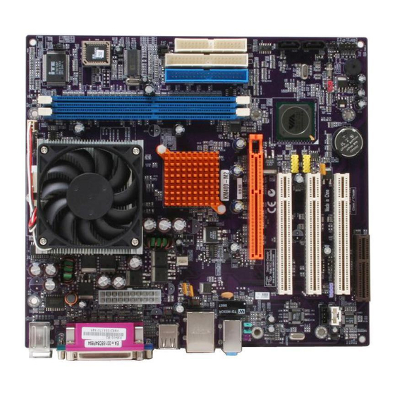
Motherboard Components Introducing the Motherboard... - Page 11 Table of Motherboard Components LABEL COMPONENT 1 CPU Socket Socket-A for AMD K7 CPUs 2 CPUFAN1 CPU cooling fan connector 3 DIMM1~DIMM2 184-pin DDR SDRAM slots 4 JP3 BIOS flash protect jumper 5 JP8~JP9 CPU Frequency jumper 6 FDD1 Floppy disk drive connector 7 IDE2 Secondary IDE connector 8 IDE1...
- Page 12 Memo Introducing the Motherboard...
-
Page 13: Installing The Motherboard
Make sure that your case supports all the features required. Secondly, KM400-M2 supports one or two floppy diskette drives and four enhanced IDE drives. Make sure that your case has sufficient power and space for all drives that you intend to install. -
Page 14: Checking Jumper Settings
Do not over-tighten the screws as this can stress the motherboard. Checking Jumper Settings This section explains how to set jumpers for correct configuration of the motherboard. Setting Jumpers Use the motherboard jumpers to set system configuration options. Jumpers with more than one pin are numbered. -
Page 15: Checking Jumper Settings
Checking Jumper Settings The following illustration shows the location of the motherboard jumpers. Pin 1 is labeled. Jumper Settings Jumper Type Description Setting (default) 1-2: NORMAL 3-pin CLEAR CMOS 2-3: CLEAR Before clearing the CMOS, make sure to turn the system off. 1-2: ENABLE 3-pin BIOS FLASH... -
Page 16: Connecting Case Components
Connecting Case Components After you have installed the motherboard into a case, you can begin con- necting the motherboard components. Refer to the following: Connect the CPU cooling fan cable to CPUFAN1. Connect the case cooling fan connector to CASFAN1. Connect the case switches and indicator LEDs to the PANEL1. -
Page 17: Front Panel Header
ACPI LED function S4/S5 Light Blinking Blinking Dark ATX1: ATX 20-pin Power Connector Signal Name Signal Name +3.3V +3.3V +3.3V -12V Ground Ground PS ON# Ground Ground Ground Ground Ground PWRGD +5VSB +12V Front Panel Header The front panel header (PANEL1) provides a standard set of switch and LED headers commonly found on ATX or Micro ATX cases. -
Page 18: Installing Hardware
Hard Drive Activity LED Connecting pins 1 and 3 to a front panel mounted LED provides visual indication that data is being read from or written to the hard drive. For the LED to function properly, an IDE drive should be connected to the onboard IDE interface. The LED will also show activity for devices connected to the SCSI (hard drive activity LED) connector. -
Page 19: Cpu Installation Procedure
Warning: Over-clocking components can adversely affect the reliability of the system and introduce errors into your system. Over-clocking can permanently damage the motherboard by generating excess heat in components that are run beyond the rated limits. This motherboard has a Socket-462 socket. When choosing a processor, consider the performance requirements of the system. -
Page 20: Installing Memory Modules
Installing Memory Modules This motherboard accommodates two 184-pin 2.5V unbuffered Double Data Rate (DDR)SDRAM (Synchronous Dynamic Random Access Memory) memory modules. It can support DDR333/266/200 (PC2700/PC2100/PC1600 Double-Data-Rate DRAM) memory modules. The total memory capacity is 2GB. DDR SDRAM memory module table Memory module Memory Bus DDR200... -
Page 21: Installing A Hard Disk Drive/Cd-Rom/Sata Hard Drive
Installing a Hard Disk Drive/CD-ROM/SATA Hard Drive This section describes how to install IDE devices such as a hard disk drive and a CD-ROM drive. About IDE Devices Your motherboard has a primary and secondary IDE channel interface (IDE1 and IDE2). An IDE ribbon cable supporting two IDE devices is bundled with the motherboard. - Page 22 About SATA Connectors Your motherboard features two SATA connectors supporting a total of two drives. SATA refers to Serial ATA (Advanced Technology Attachment) is the standard interface for the IDE hard drives which are currently used in most PCs. These connectors are well designed and will only fit in one orientation.
-
Page 23: Installing A Floppy Diskette Drive
Installing a Floppy Diskette Drive The motherboard has a floppy diskette drive (FDD1) interface and ships with a diskette drive ribbon cable that supports one or two floppy diskette drives. You can install a 5.25- inch drive and a 3.5-inch drive with various capacities. The floppy diskette drive cable has one type of connector for a 5.25-inch drive and another type of connector for a 3.5-inch drive. -
Page 24: Installing Add-On Cards
Installing Add-on Cards The slots on this motherboard are designed to hold expansion cards and connect them to the system bus. Expansion slots are a means of adding or enhancing the motherboard’s features and capabilities. With these efficient facilities, you can increase the motherboard’s capabili- ties by adding hardware that performs tasks that are not part of the basic system. -
Page 25: Connecting Optional Devices
Follow these instructions to install an add-on card: Remove a blanking plate from the system case corresponding to the slot you are going to use. Install the edge connector of the add-on card into the expansion slot. Ensure that the edge connector is correctly seated in the slot. Secure the metal bracket of the card to the system case with a screw. - Page 26 SATA1/SATA2: Serial ATA connectors These connectors are use to support the new Serial ATA devices for the highest date transfer rates (150 MB/s), simpler disk drive cabling and easier PC assembly. It eliminates limitations of the current Parallel ATA interface. But maintains register compatibility and software compatibility with Parallel ATA.
- Page 27 AUDIO1: Front Panel Audio header This header allows the user to install auxiliary front-oriented microphone and line-out ports for easier access. Signal Name Function AUD_MIC Front Panel Microphone input signal AUD_GND Ground used by Analog Audio Circuits AUD_MIC_BIAS Microphone Power AUD_VCC Filtered +5V used by Analog Audio Circuits AUD_F_R...
-
Page 28: Connecting I/O Devices
Connecting I/O Devices The backplane of the motherboard has the following I/O ports: PS2 Mouse Use the upper PS/2 port to connect a PS/2 pointing device. PS2 Keyboard Use the lower PS/2 port to connect a PS/2 keyboard. Parallel Port (LPT1) Use LPT1 to connect printers or other parallel communications devices. -
Page 29: Using Bios
Chapter 3 Using BIOS About the Setup Utility The computer uses the latest Award BIOS with support for Windows Plug and Play. The CMOS chip on the motherboard contains the ROM setup instructions for configuring the motherboard BIOS. The BIOS (Basic Input and Output System) Setup Utility displays the system’s configura- tion status and provides you with options to set system parameters. -
Page 30: Bios Navigation Keys
Press DEL to enter SETUP Pressing the delete key accesses the BIOS Setup Utility: Phoenix-AwardBIOS CMOS Setup Utility: Standard CMOS Features Frequency/Voltage Control Advanced BIOS Features Load Fail-Safe Defaults Advanced Chipset Features Load Optimized Defaults Integrated Peripherals Set Supervisor Password Power Management Setup Set User Password Save &... -
Page 31: Updating The Bios
Updating the BIOS You can download and install updated BIOS for this motherboard from the manufacturer’s Web site. New BIOS provides support for new peripherals, improvements in performance, or fixes for known bugs. Install new BIOS as follows: If your motherboard has a BIOS protection jumper, change the setting to allow BIOS flashing. -
Page 32: Standard Cmos Features
Standard CMOS Features This option displays basic information about your system. Phoenix-AwardBIOS CMOS Setup Utility Standard CMOS Features Date (mm:dd:yy) Mon, Nov 17 2003 Item Help Time (hh:mm:ss) 13 : 4 : 54 IDE Primary Master IDE Primary Slave IDE Secondary Master Menu Level IDE Secondary Slave Drive A... - Page 33 If you are setting up a new hard disk drive that supports LBA mode, more than one line will appear in the parameter box. Choose the line that lists LBA for an LBA drive. IDE Primary/Secondary Master/Slave (Auto) Leave this item at Auto to enable the system to automatically detect and configure IDE devices on the channel.
-
Page 34: Advanced Bios Features
Advanced BIOS Features This option defines advanced information about your system. Phoenix-AwardBIOS CMOS Setup Utility Advanced BIOS Features Item Help ATA 66/100 IDE Cable Msg. [Enabled] Quick Power On Self Test [Enabled] First Boot Device [Floppy] Menu Level Second Boot Device [HDD-0] Third Boot Device [CDROM]... - Page 35 Gate A20 Option (Fast) This item defines how the system handles legacy software that was written for an earlier generation of processors. Leave this item at the default value. Typematic Rate Setting (Disabled) If this item is enabled, you can use the following two items to set the typematic rate and the typematic delay settings for your keyboard.
-
Page 36: Advanced Chipset Features
Advanced Chipset Features These items define critical timing parameters of the motherboard. You should leave the items on this page at their default values unless you are very familiar with the technical specifications of your system hardware. If you change the values incorrectly, you may introduce fatal errors or recurring instability into your system. - Page 37 DRAM Clock (By SPD) This item enables you to manually set the DRAM Clock. We recommend that you leave this item at the default value. DRAM Timing (Auto By SPD) Set this to the default value to enable the system to automatically set the SDRAM timing by SPD (Serial Presence Detect).
- Page 38 AGP & P2P Bridge Control (Press Enter) Scroll to this item and press <Enter> to view the following screen: Phoenix-AwardBIOS CMOS Setup Utility AGP & P2P Bridge Control AGP Aperture Size [128M] Item Help AGP Mode [4X] AGP Driving Control [Auto] AGP Driving Value Menu Level...
-
Page 39: Integrated Peripherals
VGA Share Memory Size (32M) This item allows you to select the shared memory size for VGA usage. Press <Esc> to return to the Advanced Chipset Features screen. System BIOS Cacheable (Disabled) When this item is enabled, the System BIOS will be cached for faster execution. Video RAM Cacheable (Disabled) When this is enabled, the Video RAM will be cached resulting to better performance. - Page 40 OnChip SATA (Enabled) This option allows you enable or disable the onboard Serial ATA device. On-Chip IDE Channel 0/1 (Enabled) Use these items to enable or disable the PCI IDE channels that are integrated on the motherboard. IDE Prefetch Mode (Enabled) The onboard IDE drive interfaces supports IDE prefetching, for faster drive access.
- Page 41 MC97 Modem (Auto) Enables and disables the onboard modem. Disable this item if you are going to install an external modem. OnChip USB Controller (Enabled) Enable this item if you plan to use the Universal Serial Bus ports on this mainboard. USB 2.0 Support (Enabled) Enable this item if want to use the USB 2.0.
-
Page 42: Power Management Setup
Onboard Parallel Port (378/IRQ7) This option is used to assign the I/O address and interrupt request (IRQ) for the onboard parallel port. Parallel Port Mode (ECP) Enables you to set the data transfer protocol for your parallel port. There are four options: SPP (Standard Parallel Port), EPP (Enhanced Parallel Port), ECP (Extended Capabilities Port), and ECP+EPP. - Page 43 Power Management Option (User Define) This item acts like a master switch for the power-saving modes and hard disk timeouts. If this item is set to Max Saving, power-saving modes occur after a short timeout. If this item is set to Min Saving, power-saving modes occur after a longer timeout. If the item is set to User Define, you can insert your own timeouts for the power-saving modes.
- Page 44 IRQ/Event Activity Detect (Press Enter) Scroll to this item and press <Enter> to view the following screen: Phoenix-AwardBIOS CMOS Setup Utility IRQ/Event Activity Detect Item Help [OFF] LPT & COM [LPT/COM] HDD & FDD [ON] Menu Level PCI Master [OFF] When select Pass- PowerOn by PCI Card [Enabled]...
-
Page 45: Pnp/Pci Configurations
IRQs Activity Monitoring (Press Enter) This screen enables you to set IRQs that will resume the system from a power saving mode. Phoenix-AwardBIOS CMOS Setup Utility IRQs Activity Monitoring Primary INTR [ON] Item Help IRQ3 (COM2) [Enabled] IRQ4 (COM1) [Enabled] Menu Level IRQ5 (LPT2) [Enabled]... -
Page 46: Pc Health Status
Resources Controlled By (Auto(ESCD)) You should leave this item at the default Auto(ESCD). Under this setting, the system dynamically allocates resources to Plug and Play devices as they are required. If you cannot get a legacy ISA (Industry Standard Architecture) expansion card to work properly, you might be able to solve the problem by changing this item to Manual, and then opening up the IRQ Resources submenu. -
Page 47: Frequency/Voltage Control
Frequency/Voltage Control This item enables you to set the clock speed and system bus for your system. The clock speed and system bus are determined by the kind of processor you have installed in your system. Phoenix-AwardBIOS CMOS Setup Utility Frequency/Voltage Control Auto Detect PCI/DIMM Clk [Enabled]... -
Page 48: Load Fail-Safe Defaults
Load Fail-Safe Defaults Option This option opens a dialog box that lets you install fail-safe defaults for all appropriate items in the Setup Utility: Press <Y> and then <Enter> to install the defaults. Press <N> and then <Enter> to not install the defaults. -
Page 49: Save & Exit Setup Option
Save & Exit Setup Option Highlight this item and press <Enter> to save the changes that you have made in the Setup Utility and exit the Setup Utility. When the Save and Exit dialog box appears, press <Y> to save and exit, or press <N> to return to the main menu: Exit Without Saving Highlight this item and press <Enter>... - Page 50 Memo Using BIOS...
-
Page 51: Using The Motherboard Software
Chapter 4 Using the Motherboard Software About the Software CD-ROM The support software CD-ROM that is included in the motherboard package contains all the drivers and utility programs needed to properly run the bundled products. Below you can find a brief description of each software program, and the location for your motherboard version. -
Page 52: Running Setup
Setup Tab Setup Click the Setup button to run the software installation program. Select from the menu which software you want to install. Browse CD The Browse CD button is the standard Windows command that allows you to open Windows Explorer and show the contents of the support Before installing the software from Windows Explorer, look for a file named README.TXT, INSTALL.TXT or something similar. - Page 53 Click Next. The following screen appears: Check the box next to the items you want to install. The default options are recommended. Click Next run the Installation Wizard. An item installation screen appears: Follow the instructions on the screen to install the items. Drivers and software are automatically installed in sequence.
-
Page 54: Manual Installation
Manual Installation Insert the CD in the CD-ROM drive and locate the PATH.DOC file in the root directory. This file contains the information needed to locate the drivers for your motherboard. Look for the chipset and motherboard model; then browse to the directory and path to begin installing the drivers. -
Page 55: Via Vt8237 Sata Raid Setup Guide
Chapter 5 VIA VT8237 SATA RAID Setup Guide VIA RAID Configurations The motherboard includes a high performance Serial ATA RAID controller integrated in the VIA VT8237 Southbridge chipset. It supports RAID 0, RAID 1 and JBOD with two indepen- dent Serial ATA channels. RAID: (Redundant Array of Independent Disk Drives) use jointly several hard drives to increase data transfer rates and data security. -
Page 56: Entering Via Tech Raid Bios Utility
Install the Serial ATA hard disks into the drive bays. Connect one end of the Serial ATA cable to the motherboard’s primary Serial ATA connector (SATA1). Connect the other end of Serial ATA cable to the master Serial ATA hard disk. Connect one end of the second Serial ATA cable to the motherboard’s sec- ondary Serial ATA connector (SATA2). - Page 57 Create Array In the VIA RAID BIOS utility main menu, select Create Array then press the <Enter> key. The main menu items on the upper-left corner of the screen are replaced with create array menu options. RAID 0 for performance Select the second option item Array Mode, then press the <Enter>...
- Page 58 Select Start Create Process and press <Enter> to setup hard disk for RAID system. The following confirmation appears: The same confirmation message appears when the Auto Setup for Performance option is selected. Press “Y” to confirm or “N” to return to the configuration options. RAID 1 for data protection Select the second option item Array Mode, then press the <Enter>...
- Page 59 Delete Array In the VIA RAID BIOS utility main menu, select Delete Array then press the <Enter> key. The focus is directed to the list of channel used for IDE RAID arrays. Press the <Enter> key to select a RAID array to delete. The following confir- mation message appears.
-
Page 60: Duplicate Critical Raid 1 Array
Duplicate Critical RAID 1 Array When booting up the system, BIOS will detect if the RAID 1 array has any inconsistencies between user data and backup data. If BIOS detects any inconsistencies, the status of the disk array will be marked as critical, and BIOS will prompt the user to duplicate the RAID 1 in order to ensure the backup data consistency with the user data. - Page 61 1. Power off and Check the Failed Drive: This item turns off the computer and replaces the failed hard drive with a good one. If your computer does not support APM, you must turn off your computer manually. After replacing the hard drive, boot into BIOS and select Choose replacement drive and rebuild to rebuild the broken array.
-
Page 62: Installing Raid Software & Drives
Windows XP installation. Existing Windows XP Driver Installation Insert the ECS CD into the CD-ROM drive. The CD will auto-run and the setup screen will appear. Under the Driver tab, click on VIA SATA RAID Utility. - Page 63 VIA SATA RAID utility • RAID0 and RAID1 functions Insert the ECS CD and click on the Setup to install the software. The InstallShield Wizard will begin automatically for installation. Click on the Next button to proceed the installation in the welcoming window.
-
Page 64: Using Via Raid Tool
Put a check mark in the check box to install the feature you want. Then click Next button to proceed the installation. Using VIA RAID Tool Once the installation is complete, go to Start---> Programs---> VIA---> raid_tool.exe to enable VIA RAID Tool. After the software is finished installation, it will automatically started every time Windows is initiated. - Page 65 The main interface is divided into two windows and the toolbar above contain the main functions. Click on these toolbar buttons to execute their specific functions. The left windowpane displays the controller and disk drives and the right windowpane displays the details of the controller or disk drives.
- Page 66 Click on the plus (+) symbol next to Array 0--RAID 0 to see the details of each disk. You may also use the same button to view the statuses of Array 0-- RAID 1. VIA VT8237 SATA RAID Setup Guide...
- Page 67 Click on the plus (+) symbol next to Array 0; RAID 1 to see the details of each disk. VIA VT8237 SATA RAID Setup Guide...
Need help?
Do you have a question about the KM400-M2 and is the answer not in the manual?
Questions and answers