Table of Contents
Advertisement
Quick Links
Advertisement
Table of Contents

Subscribe to Our Youtube Channel
Related Manuals for ECS Photon Extreme KN3 SLI2


Summary of Contents for ECS Photon Extreme KN3 SLI2
-
Page 2: Table Of Contents
Updating and Recovering the BIOS............3-1 Major Components...................1-5 ........ Using AWARD Flash to update your BIOS..3-1 Headers and Connectors................1-7 ....... Using ECS Top-Hat Flash to recover your BIOS. .3-2 Jumpers.....................1-11 The Main Menu..................3-3 Rear Panel....................1-12 Standard CMOS Features............3-3 CHAPTER 2 Advanced BIOS Features............3-4 Advanced Chipset Features............3-8... - Page 3 Set Supervisor/User Password............3-20 CHAPTER 6 Save & Exit Setup................3-21 NVIDIA® MediaShield RAID configurations...........6-1 ............6-1 Exit Without Saving.................3-21 Setting the BIOS RAID items CHAPTER 4 Entering the NVIDIA® MeidaShield RAID Utility........6-1 Creating a RAID Volume............... 6-2 Software CD Information.................4-1 Rebuilding a RAID array..............6-3 Running the Software CD.................4-1 Deleting a RAID array..............6-4 Setup Tab....................4-1...
- Page 4 This chapter entails the newest technology and rich features on the Photon Extreme motherboard.
- Page 5 Reference Introduction............1-1 Package Check List...........1-1 Feature Summary...........1-2 Special Features..........1-3 Major Components........1-5 Headers and Connectors........1-7 Jumpers............1-11 Rear Panel...........1-12...
-
Page 6: Chapter 1 Introduction
1.1 Introduction 1.2 Package Check List User’s Guide Thank you for choosing the ECS KN3 SLI2 Extreme motherboard Motherboard Installation CD The KN3 SLI2 Extreme is the next generation of high performance motherboard designed to support the AMD Socket M2... -
Page 7: Feature Summary
1.3 Feature Summary • Socket AM2 for Athlon 64 FX/Athlon 64 X2 Dual- - RAID0, RAID1 & JBOD configuration Core/Athlon 64/Sempron CPUs - Support NCQ & eSATA & Hot Plug & Port Multiplier • High-performance HyperTransport CPU Interface IEEE 1394a •... -
Page 8: Special Features
1.4 Special Features • 1 x 24-pin ATX Power Supply Connector Internal I/O Extreme Power Extreme Power Extreme Power Extreme Power Extreme Power • 1 x 4-pin 12V Connector The most efficient algorithm! • 1 x Auxiliary 4-pin + 12V connector for grapics cards •... - Page 9 Extreme Link Extreme Link Extreme Link Extreme Link Extreme Link Extreme Genius Extreme Genius Extreme Genius Extreme Genius Extreme Genius A “time machine” to More options for data stor- Color-coding for easy connec- protect and restore files! Add peripherals and con- age! tions! sumer electronics devices!
-
Page 10: Major Components
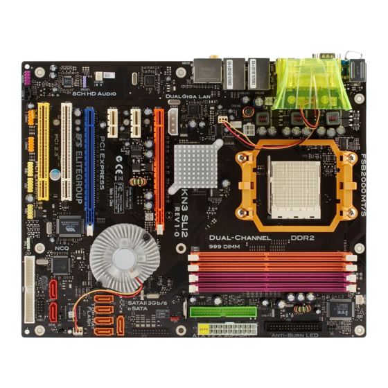
1.5 Major Components 1. CPU Socket Socket AM2 surface mount, Zero Insertion Force socket for AMD Processor Athlon 64 FX/Athlon 64 X2 Dual- Core/Athlon 64/Sempron supports FSB 1000/800/600/400/200 MHz HyperTransport (HT) interface speeds that allows up to 8 GB/s data transfer rates. 2. - Page 11 6. Flash ROM 12. PCI Express x1 slots (PCIE2 slot & PCIE3 slot) This flash ROM contains the programmable BIOS program. There are two PCI Express x1 slots that are fully compliant to the PCI 7. Serial ATA controller Express Base Specification revision 1.0a. This motherboard incorporates onboard Serial ATA controller, support- 13.
-
Page 12: Headers And Connectors
1.6 Headers and Connectors 1. CASFAN1~3 (Cooling Fan Connectors, 3 pin) These connectors allow you to link with the cooling fans to lower the system temperature. 2. CPUFAN1 (CPU Fan Connector, 4 pin) Please note, a proper installation of the CPU cooler is essential to pre- vent the CPU from running under abnormal conditions or being dam- aged by overheating. - Page 13 4. IR1 (Infrared Header, 6-1 pin) AC power cord should only be connected to your power supply until after ATX power cable and other related devices are firmly connected to the motherboard. Make sure that your ATX12V power supply can pro- vide 8A of 12V and at least 1A on the +5V standby.
- Page 14 12. SATA 7/8 (Serial ATA RAID Connectors, 7 pin) 9. LPT2 (Parallel Port Header, 26-1 pin) These two Serial ATA Generation 2 connectors, with transfer rate of 3.0 Gb/s, supporting SATA hard disks that you may configure as a Connect the printer, scanner, or other device to this header. RAID set.
- Page 15 15. USB 1/2/3 (Front USB Headers, 10-1 pin) 18. AUDIO1 (Front Panel Audio Header, 10-1 pin) This is an interface for the Intel front panel audio cable that allows convenient connection and control of audio devices. By default, the If the USB ports on the rear panel are inadequate, three USB headers are pins labeled LINE2_RR/RET_R and the pins LINE2_RL/RET_L are available for additional USB ports.
-
Page 16: Jumpers
1.7 Jumpers 1. JP1 (CLEAR CMOS) This jumper allows you to clear the Real Time Clock (RTC) RAM in CMOS. You can clear the CMOS memory of date, time, and system setup parameters by erasing the CMOS RTC RAM data. Before clearing the CMOS data, make sure to turn the system off. -
Page 17: Rear Panel
1.8 Rear Panel 6. Front Out Jack * This jack connects a tape player or other audio sources. In 8-channel mode, the function of this jack is Front speaker out. 7. Back Surround Jack * This jack connects a tape player or other audio sources. In 8-channel mode, the function of this jack is Back-Surround speaker out 8. - Page 18 13. PS/2 keyboard port This 6-pin connector is for connecting PS/2 keyboard. 1-13...
- Page 19 1-14...
- Page 20 This chapter explains the hardware setup procedure for this motherboard, such as installing the CPU, memory modules, expansion cards, as well as the jumpers...
- Page 21 Reference Installing the CPU..........2-1 Installing the CPU cooling FAN......2-1 Installing Memory Module.........2-2 Connecting IDE, Floppy and SATA cable...2-4 Installing Motherboard in a case......2-4 Connecting IDE, Floppy & SATA Device...2-5 Installing Expansion cards........2-5 Connecting the Power supply cable....2-6 Powering up............2-6...
-
Page 22: Chapter 2 Installing The Cpu
2.1 Installing the CPU 2. Make sure the CPU fan is plugged to the CPU fan connector. Please refer to the CPU 1. Angling the rod to 65-degree may feel cooling fan user’s manual for more detail Actual angle tight, continue to pull the rod to 90- installation procedure. -
Page 23: Installing Memory Module
Table A: DDR2 (memory module) QVL (Qualified Vendor List) 2.3 Installing Memory Module The following DDR2 memory modules have been tested and qualified 1. Push the latches on each side of the DIMM for use with this motherboard. slot down. 2. - Page 24 Table C: Recommended dual-channel DDR configurations Table B Unbuffered DIMM Address Timings and Drive Strengths for AM2 Package DDR1 DDR2 DDR3 DDR4 Dual Channel DRAM DIMM1 DIMM2 Timing Address Timing Output Driver √ √ √ Speed Mode Control Register Compensation Control Register √...
-
Page 25: Connecting Ide, Floppy And Sata Cable
2.4 Connecting IDE, Floppy and SATA cable 2.5 Installing Motherboard in a case 1. Connect the IDE/Floppy disk ribbon cable. Make sure the side of 1. Place the motherboard over the mounting brackets. the cable with the red stripe on it is plugged into pin 1 side of the 2. -
Page 26: Connecting Ide, Floppy & Sata Device
2.6 Connecting IDE, Floppy & SATA Device 2.7 Installing Expansion cards 1. Open the chassis and then remove the slot bracket from the case 1. If installing two IDE devices on the same where you will be installing the expansion cards. ribbon cable, one device must be set to 2. -
Page 27: Connecting The Power Supply Cable
2.8 Connecting the Power supply cable With ATX v2.x power supply, users please The ATX power connector is keyed for proper insertion. There are two note that when installing 24-pin power connectors for 4-pin and 24-pin ATX power cable. The plastic clip on cable, the latch of power cable connector the power connector should lock over the plastic tab on the clings to the right side of the ATX connec-... - Page 28 In this chapter, you will learn how to adjust the BIOS (Basic Input and Output System) setup menus. It provides information on the system’s configuration status and options to setup system parameters.
- Page 29 3.3-12 Save & Exit Setup............3-21 3.3-13 Exit Without Saving..........3-21 Updating and Recovering the BIOS....3-1 3.2-1 Using AWARD Flash to update your BIOS....3-1 3.2-2 Using ECS Top-Hat Flash to recover your BIOS..3-2 The Main Menu..........3-3 3.3-1 Standard CMOS Features........3-3 3.3-2 Advanced BIOS Features.........3-4 3.3-3 Advanced Chipset Features........3-8...
-
Page 30: Entering The Bios Setup Menu
Frequency/Voltage Control Standard CMOS Features 3. Use the Award Flash Utility from the ECS support CD and download Load Performance Defaults Advanced BIOS Features the last BIOS file for this motherboard from ECS web site... -
Page 31: Using Ecs Top-Hat Flash To Recover Your Bios
7. Download the BIOS file from ECS web site (www.ecs.com.tw) or ECS support CD and use Flash Utility to reflash the original Flash ROM. 8. You can choose either AWARD Flash utility in DOS mode or ECS “EZ Flash Utility” in windows to reflash the BIOS. -
Page 32: The Main Menu
Date and Time 3.3 The Main Menu The Date and Time items show the current date and time on the computer. If you are The main menu of the Setup Utility displays a list of the options that are running a Windows OS, these items are automatically updated whenever you make available. -
Page 33: Advanced Bios Features
IDE HDD Auto-Detection Halt On (All, But Keyboard) Press <Enter> while this item is highlighted to prompt the Setup Utility to automatically This item defines the operation of the system POST (Power On Self Test) routine. detect and configure an IDE device on the IDE channel. You can use this item to select which types of errors in the POST are sufficient to halt the system. - Page 34 CPU Feature (Press Enter) Removable Device Prioritiy (Press Enter) Scroll to this item and press <Enter> to view the following screen: Scroll to this item and press <Enter> to view the following screen: Phoenix-Award WorkstationBIOS CMOS Setup Utility Phoenix-Award WorkstationBIOS CMOS Setup Utility CPU Feature Removable Device Priority Item Help...
- Page 35 Hard Disk Boot Priority (Press Enter) CPU Internal Cache (Enabled) Scroll to this item and press <Enter> to view the following screen: All processors that can be installed in this mainboard use internal level 1 (L1) and external level 2 (L2) cache memory to improve performance. Leave this item at the Phoenix-AwardBIOS CMOS Setup Utility default value for better performance.
- Page 36 Boot Other Device (Enabled) Security Option (Setup) When enabled, the system searches all other possible locations for an operating If you have installed password protection, this item defines if the password is system if it fails to find one in the devices specified under the First, Second, and Third required at system start up, or if it is only required when a user tries to enter the boot devices.
-
Page 37: Advanced Chipset Features
3.3-3 Advanced Chipset Features K8 NB HT Speed/Width/NB SB HT Speed/Width (Auto) This item enables users to manually set up the HyperTransport speed and width. These items define critical timing parameters of the mainboard. You should leave the items on this page at their default values unless you are DRAM Configuration (Press Enter) very familiar with the technical specifications of your system hardware. - Page 38 Timing Mode (Auto) Memory Hole Remapping (Enabled) This item allows you to set up the DRAM timing manually or automatically. This Remaps the memory used by the BIOS (A0000 to FFFF - 384 k) above the 1 Mb item is set to [Auto] by default. When setting to [Manual], the following items are limit.
- Page 39 memory CAS (column address strobe).It is recommended that you leave PCIE Spread Spectrum (Disabled) this item at the default value. The 2T setting requires faster memory that This item, when enabled, can significantly reduce the EMI (Electromagnetic Interference) specifically supports this mode. generated by the PCIE.
-
Page 40: Integrated Peripherals
3.3-4 Integrated Peripherals IDE Function Setup (Press Enter) Scroll to this item and press <Enter> to view the following screen: These options display items that define the operation of peripheral Phoenix-Award WorkstationBIOS CMOS Setup Utility components on the system’s input/output ports. IDE Function Setup Phoenix-Award WorkstationBIOS CMOS Setup Utility Item Help... - Page 41 Primary/Secondary Master/Slave UDMA (Auto) RAID Config (Press Enter) Scroll to this item and press <Enter> to view the following screen: Each IDE channel supports a master device and a slave device. This motherboard Phoenix-Award WorkstationBIOS CMOS Setup Utility supports UltraDMA technology, which provides faster access to IDE devices. RAID Config If you install a device that supports UltraDMA, change the appropriate item on this list to Auto.
- Page 42 Init Display First (PCIE Slot) Power On Password (Enter) Use this item to specify whether your graphics adapter is installed in one of the Press Enter and key in the password for Keyboard power on. PCI slots or is integrated on the motherboard. If a PCI graphics card is installed, Hot Key Power ON (Ctrl-F1) the onboard VGA will be disabled.
-
Page 43: Power Management Setup
3.3-5 Power Management Setup Onboard Parallel Port (378/IRQ7) This option lets you control system power management. The system has This option is used to assign the I/O address and interrupt request (IRQ) for the onboard parallel port. various power-saving modes including powering down the hard disk, turning Parallel Port Mode (SPP) off the video, suspending to RAM, and software power down that allows the system to be automatically resumed by certain events. - Page 44 PWRON After PWR-Fail (OFF) button causes a software power down. If the item is set to Delay 4 Sec. then you have to hold the power button down for four seconds to cause a software power down. This item enables your computer to automatically restart or return to its last operating Resume By PCI PME (Enabled) status.
-
Page 45: Pnp/Pci Configurations
3.3-6 PnP/PCI Configurations Reset Configuration Data (Disabled) If you enable this item and restart the system, any Plug and Play configuration data These options configure how PnP (Plug and Play) and PCI expansion cards stored in the BIOS Setup is cleared from memory. operate in your system. -
Page 46: Pc Health Status
3.3-7 PC Health Status Smart Fan Function (Press Enter) On motherboards that support hardware monitoring, this item lets you Scroll to this item and press <Enter> to view the following screen: monitor the parameters for critical voltages, temperatures and fan speeds. Phoenix-Award WorkstationBIOS CMOS Setup Utility Phoenix-Award WorkstationBIOS CMOS Setup Utility Smart Fan Function... -
Page 47: Frequency/Voltage Control
Shutdown Temperature (Disabled) 3.3-8 Frequency/Voltage Control Enables you to set the maximum temperature the system can reach before powering down. This item enables you to set the clock speed and system bus for your system. Warning Temperature (Disabled) The clock speed and system bus are determined by the kind of processor you have installed in your system. -
Page 48: Load Performance Defaults
DIMM Voltage Control (1.80V) 3.3-9 Load Performance Defaults This item allows users to adjust DIMM voltage. The higher you set the voltage, If you select this item and press Enter a dialog box will appear. If you select the more likely you will cause damage to your CPU or DIMM. [OK], and then Enter, the Setup Utility loads a set of performance default Adjust Extra NB Vcore (1.200V) values. -
Page 49: Load Optimized Defaults
3.3-10 Load Optimized Defaults 3.3-11 Set Supervisor/User Password This option opens a dialog box that lets you install optimized defaults for all When this function is selected, the following message appears at the center appropriate items in the Setup Utility. Press <Y> and then <Enter> to of the screen to assist you in creating a password. -
Page 50: Save & Exit Setup
if Supervisor Password is enabled. 3.3-12 Save & Exit Setup Highlight this item and press <Enter> to save the changes that you have made in the Setup Utility and exit the Setup Utility. When the Save and Exit dialog box appears, press <Y> to save and exit, or press <N> to return to the main menu. - Page 51 3-22...
- Page 52 This chapter delivers contents of the ECS support CD.
- Page 53 Reference Software CD Information........4-1 Running the Software CD........4-1 Setup Tab............4-1 Application Tab..........4-2 Read Me Tab............4-2 Software Utilities Introduction......4-2...
-
Page 54: Software Cd Information
4.1 Software CD Information 4.3 Setup Tab The support software CD-ROM that is included in the motherboard package The setup tab shows three buttons - Setup, Browse CD, Exit. contains all the drivers and utility programs needed to properly run the Setup button: Click the Setup button to run the software installation bundled products. -
Page 55: Application Tab
4.4 Application Tab 2. Click Next . The following screen appears: Lists the software utilities that are available on the CD. 4.5 Read Me Tab Displays the path for all software and drivers available on the CD. 4.6 Software Utilities Introduction AWARD Flash Memory Utility This utility lets you erase the system BIOS stored on a Flash Memory 3. - Page 56 I’m InTouch features and enhancements such as improved picture quality, easier-to-use I’m InTouch remote access software allows you to login and work on Time-Stretching, MP3 playback, and Video Desktop - which lets you your far-away computer, just as if you were sitting behind it! Run watchmovies under your desktop icons while you work or check email.
- Page 57 Adobe Reader need to make changes to the BIOS or reboot your system. This item install the Adobe Acrobat Reader. The Acrobat Reader software is for viewing files saved in Portable Document Format (PDF). Smart LAN The motherboard support Marvell Virtual Cable Tester (VCT) technology. It enables end users to remotely diagnose the quality and characteristics of the attached cable.
- Page 58 In this chapter, you will learn how to install SLI-ready graphics cards...
- Page 59 Reference Overview............5-1 Installing SLI-ready graphics cards....5-1 Installing the device driver........5-4 Enabling the multi-GPU feature in Windows..5-4...
-
Page 60: Chapter 5 Overview
NVIDIA certified. for the SLI connector. 2. Visit the ECS website (www.ecs.com.tw) for a list of qualified SLI- ready graphics cards for this motherboard. 3. Make sure that your graphics card driver supports the NVIDIA technology. Download the latest driver from the NVIDIA website (www.nvidia.com). - Page 61 2. Insert one graphics card into 4. Align and insert the SLI card PCIE1 or PCIE4 slot. Make sure bridge to the goldfinger on each that the card is properly seated on graphics card. Make sure that the the slot. connector is firmly in place.
- Page 62 6. Remove any of the two bracket 8. Connect a VGA cable or a DVI-I cable to the graphics card installed covers between the graphics cards. on the PCIE1 PCI Express slot. Bracket slot 7. Align and insert the retention bracket into the slot then secure it with a screw.
-
Page 63: Installing The Device Driver
5.3 Installing the device driver 2. From the pop-up menu, select nView Desktop Manager then click nView Properties. Refer to the documentation that came with your graphics card package to install the device drivers. Make sure that your PCI Express graphics card driver supports the NVIDIA SLI technology. - Page 64 7. Click on the slider to display the 5. From the Display Properties dialog following screen, then select the box, select the Settings tab then SLI multi-GPU item. click Advanced. Slider 6. Select the NVIDIA GeForce tab. 8. Click the Enable SLI multi-GPU check box. 9.
- Page 65 In this chapter, you will learn how to set the NVIDIA® MediaShield RAID configurations and JMicron ® RAID Configurations.
- Page 66 Reference NVIDIA® MediaShield RAID configurations..6-1 6.2-7 Rebuilding a Mirror Drive........6-11 6.1-1 Setting the BIOS RAID items........6-1 6.2-8 Saving the settings and existing setup ....6-12 6.1-2Entering the NVIDIA® MeidaShield RAID Utility.6-1 6.1-3Creating a RAID Volume..........6-2 6.1-4 Rebuilding a RAID array..........6-3 6.1-5Deleting a RAID array........6-4 6.1-6Clearing a disk data...........
-
Page 67: Nvidia® Mediashield Raid Configurations
6.1 NVIDIA® MediaShield RAID configurations 6.1-2 Entering the NVIDIA® MeidaShield RAID utility The motherboard includes a high performance RAID controller integrated in the NVIDIA® nForce™ 590 SLI southbridge chipset. It supports RAID To enter the NVIDIA® RAID utility: 0, RAID 1, RAID 0+1, RAID 5 and JBOD for six independent Serial ATA 1. -
Page 68: Creating A Raid Volume
6.1-3 Creating a RAID Volume • 8 /16 KB - low disk usage To create a RAID volume: • 64 KB - typical disk usage 1. From the NVIDIA® RAID utility Define a New Array menu, select • 128 KB - performance disk usage RAID Mode then press <Enter>. -
Page 69: Rebuilding A Raid Array
6.1-4 Rebuilding a RAID array To rebuild a RAID array: 1. From the Array List menu, use the up or down arrow keys to select a RAID array then press <Enter>. The RAID Array details appear. 5.A new set of navigation keys is displayed on the bottom of the screen. 6. -
Page 70: Deleting A Raid Array
2. Press <R> to rebuild a RAID array. The following screen appears. 4. Press <Enter> to start rebuilding array or press <Esc> to cancel. 5.After the rebuild process, the Array list menu appears. 6.1-5 Deleting a RAID array To delete a RAID array: 1. -
Page 71: Clearing A Disk Data
2. Press <D> to delete a RAID array. The following confirmation message appears. 3. Press <Y> to delete array or press <N> to cancel. Take caution in using this option. All data on the RAID drives will be lost! 4. Press <Y> to delete array or press <N> to cancel. 6.1-6 Clearing a disk data To clear disk data: A new set of navigation keys is displayed on the bottom of the screen. -
Page 72: Jmicron ® Raid Configurations
6.2 JMicron RAID Configurations ® Phoenix-AwardBIOS CMOS Setup Utility Onboard Device The JMicron Serial ATA controller allows you to configure RAID 0, RAID ® Item Help SATA Mode [IDE] USB Controller [Enabled] 1 and JBOD sets on the external Serial ATA hard disk drives. USB 2.0 Controller [Enabled] Menu Level... -
Page 73: Entering The Jmb363 Raid Bios Utility
6.2-2 Entering the JMB363 RAID BIOS utility 6.2-3 Creating a RAID set During POST, press <Ctrl-J> to enter the JBM363 RAID BIOS In the main JMB363 RAID BIOS menu, highlight Create RAID menu. Disk Drive using the up/down arrow key then press <Enter>. The main JMB363 RAID BIOS menu appears. - Page 74 When the Disks item is highlighted, use the up/down arrow key to When done, press <Enter> to confirm the creation of the RAID highlight an HDD that you want to belong to the RAID set, then set. A dialogue box appears to confirm the action. Press <Y> to press the space bar to confirm selection.
-
Page 75: Deleting A Raid Set
6.2-4 Deleting a RAID set In the main JMB363 RAID BIOS menu, highlight Delete RAID Disk Drive using the up/down arrow key then press <Enter>. Pressing <Y> deletes all the data in the HDDs. Use the space bar to select the RAID set you want to delete. A selected set shows a sign before it. -
Page 76: Solving A Mirror Confilict
6.2-6 Solving a Mirror confilict If you still want to use this broken RAID HDD as part of the RAID set configured through the JMB363, you may do so by A Mirror conflict occurs when both disks in a RAID 1 (Mirror) configuration resetting the disk to non-RAID. -
Page 77: Rebuilding A Mirror Drive
Use the space bar to select the HDD that you want to set as source 6.2-7 Rebuilding a Mirror Drive drive. When one of the disks in a RAID 1 (Mirror) configuration is unplugged from A selected HDD shows a sign before it. the system, then plugged in again, a dialogue box appears to ask you to rebuild Using the <TAB>, move to the RAID Disk Drive List menu and the Mirror drive. -
Page 78: Saving The Settings And Existing Setup
Using the <TAB>, move to the RAID Disk Drive List menu and 6.2-8 Saving the settings and exiting setup highlight the RAID set that you want to rebuild. Press <Del> to When you have finished, highlight Save & Exit Setup using the up/down begin rebuilding the Mirror configuration. - Page 79 Résumé des caractéristiques • Socket AM2 pour processeur Athlon 64 FX/Athlon 64 X2 -Prise en charge de NCQ, eSATA, Hot Plug & Dual-Core/Athlon 64/Sempron Multiplicateur de port • Interface de CPU HyperTransport de Hautes Performances: • Vitesse de transfert de 2000/1600/1200/800/400 MT/s •...
- Page 80 • 1 x Connecteur d’alimentation ATX 24 broches E/S interne • 1 x Connecteur 12 V 4 broches • 1 x Connecteur auxilliaire 4 broches +12V pour interface graphique • 1 x connecteur de lecteur de disquette- prenant en charge 360K ~ 2,88M octets, 3 Lecteurs de disquettes Modes •...
- Page 81 Zusammenfassung der Merkmale • Socket AM2 für Athlon 64 FX/Athlon 64 X2 Dual-Core/ Athlon 64/Sempron CPU Unterstützung für NCQ, eSATA, Hot Plug & Port • Hochleistungsfähiges HyperTransport CPU-Interface Multiplier • Transferrate von 2000/1600/1200/800/400 MT/s IEEE 1394a • TI IEEE1394a Controller ...
- Page 82 • 1 x 24-Pin ATX Netzteilanschluss Internes I/O • 1 x 4-Pin 12 V Stecker • 1 x Zusätzlicher 4-Pin +12V Anschluss für eine Grafikschnittstelle • 1 x Floppylaufwerkanschluss, unterstützt 360K ~ 2.88M Bytes, 3 Modus Festplatten • 2 x IDE Anschlüsse •...
- Page 83 Indice delle caratteristiche • Presa AM2 per CPU Athlon 64 FX/Athlon 64 X2 Dual-core/ NCQ, eSATA, Hot Plug e moltiplicatore di porte Athlon 64/Sempron • Interfaccia CPU HyperTransport a elevate prestazioni • Velocità di trasferimento di 2000/1600/1200/800/400 MT/s IEEE 1394a •...
- Page 84 I/O interno • 1 x connettore di alimentazione 24-pin ATX • 1 x connettore 4-pin da 12 V • connettore a +12 V a 4 pin ausiliario per interfaccia grafica • 1 x connettore floppy - supporta 360K ~ 2,88M Byte, 3 Mode FDDs •...
- Page 85 Resumen de Características • Socket AM2 para CPU Athlon 64 FX/ Athlon 64X2 Dual- - 2 x dispositivos SATAII 3.0Gb/s Core/Athlon 64/Sempron - Soporte NCQ, eSATA, Conexión en Encendido & • Interfaz de CPU HyperTransport de alto rendimiento Multiplicador de Puerto (Hot Plug & Port Multiplier) •...
- Page 86 I/O Interno • 1 x Conector de Suministro 24-pin ATX • 1 x Conector 4-pin 12 V • conector auxiliar 4-pin +12V para la Interfaz de Gráficas • 1 x conector Floppy - soporta 360K ~ 2.88M Bytes, FDD de 3 Modos •...
- Page 87 Sumário de Características • Ficha AM2 para Athlon 64 FX/Athlon 64 X2 Dual-Core/ - 2 x dispositivos SATAII 3.0Gb/s Athlon 64/Sempron CPU - Suporte NCQ, eSATA, Hot Plug & Port Multiplier • Interface de CPU de Elevada Performance e HyperTransport •...
- Page 88 • 1 x Conector de Fonte de Alimentação 24 pinos ATX I/O interno • 1 x Conector 4 pinos 12 V • 1 x 4 pinos Auxiliares + conector 12V para Interface de Gráficos • 1 x Conector flexível - suporta 360K ~ 2.88M Bytes, FDDs de 3 Modos •...
- Page 89 特徴概要 • Athlon 64 FX/Athlon 64 X2 Dual-Core/Athlon 64/ - SATAII 3.0Gb/秒装置を2つまで接続可能 プロセッサ Sempron CPUのソケット AM2を搭載 - NCQ、eSATA、Hot Plug & Port マルチプライヤをサポ • 高性能HyperTransport CPU インターフェースに対応 ート • 2000/1600/1200/800/400 MT/s転送率を実現 • IEEE 1394a VIA IEEE1394a コントローラ • • ® IEEE1394a ケーブルポートが2つで、400 Mb/sの転 チップセット...
- Page 90 • 内部入出力 1 つの24ピンATX 電源サプライコネクタ • 1 つの4ピン12 V コネクタ • 1つのグラフィック・カードの補助用4ピン+12V コネクタ • 1つのフロッピーディスクドライブコネクタ、360Kから 2.88Mバイトの3 Mode FDDをサポート • 2つのIDEコネクタ • 7つのシリアルATAコネクタ • 3つのUSB 2.0ヘッダーでさらなる6つのUSBポートを 増設可能 • 2つの1394a ヘッダー • 1つの26ピン・プリンタ・ヘッダー • 1つのフロントパネルスイッチ/LED ヘッダー • 1つのフロントパネルオーディオヘッダー • 1 つのSIR方式の IrDA ヘッダー •...
- Page 91 특성 요약 • 애슬론 64 FX/애슬론 64X2 Dual-Core/애슬론 64/ NCQ, eSATA, Hot Plug 및 Port Multiplier 지원 Sempron CPU 용 소켓 AM2 • 고 성능 HyperTransport CPU 인터페이스 IEEE 1394a • VIA IEEE1394a 컨트롤러 • 전송 속도 2000/1600/1200/800/400 MT/s • 2 x IEEE1394a 케이블...
- Page 92 • 1 x 24 핀 ATX 파워 써플라이 커넥터 내부 I/O • 1 x 4 핀 12 V 커넥터 • 그래픽 인터페이스를 위한Auxiliary 4 핀 1개+12V 커 넥터 • 1 x 플로피 커넥터- 360K ~ 2.88M Bytes, 3 모드 FDD 지 원...
- Page 93 功能摘要 • 配備有 Athlon 64 FX/Athlon 64 X2 Dual-Core/Athlon - NCQ、eSATA、熱插拔及埠多工器 中央處理器 64/Sempron CPU的AM2插座 • • VIA IEEE1394a 控制器 支援高效能HyperTransport CPU 介面 IEEE 1394a • • 提供高達2000/1600/1200/800/400 MT/s的資料傳輸率 支援2個IEEE1394a 接線埠,提供高達400 Mb/s的傳輸率 ® • NVIDIA nForce 590 SLI MCP 晶片組 • ®...
- Page 94 • 內部輸出入 1個24針ATX 電源供應器連接器 • 1個4針12 V 連接器 介面 • 1個繪圖卡用輔助4針+12V連接器 • 1個軟碟機連接器,可支援360K至2.88M位元組之3 Mode 軟碟機 • 2個IDE連接器 • 7個SATA 連接器 • 3個USB 2.0接頭,可支援6個額外的USB埠 • 2個1394a接頭 • 1個26針印表機接頭 • 1個前面板開關/LED 接頭 • 1個前面板音訊接頭 • 1個SIR級之IrDA接頭 • 1個喇叭接頭 • 1個CD-in接頭 • 1個SPDIF輸出接頭 •...
- Page 95 功能摘要 • 用于Athlon 64 FX/Athlon 64 X2 Dual-Core/ - 2 个 Ultra DMA 133/100/60 IDE设备 Athlon 64/Sempron CPU 的 Socket AM2 插座 - 2 个 SATAII 3.0Gb/s 设备 • 高性能 HyperTransport CPU 接口: - NCQ、eSATA、热插拔 & 端口扩展器 • 传输速率 2000/1600/1200/800/400 MT/s ®...
- Page 96 • 1 个 24 针 ATX 电源接口 集成 I/O • 1 个 4 针 12 V 接口 • 1 个 用于图形接口的辅助 4 针 +12V 接口 • 1 个软驱接口- 支持 360K ~ 2.88M 字节,3 Mode • 2 个 IDE 接口 • 6 个串行...
- Page 97 Характеристики • Разъем AM2 для процессоров Athlon 64 FX/Athlon 64 X2 2 устройства SATAII 3.0 Гб/с Dual-Core/Athlon 64/Sempron CPU - Поддержка RAID 0, RAID 1, e-SATA и PM • Интерфейс HyperTransport CPU с высокой пропускной способностью • Скорость передачи данных 2000/1600/1200/800/400 MT/ •...
- Page 98 Стандарт • 1 x 24-штырьковое гнездо питания ATX Внутренние • 1 x 4-штырьковое гнездо 12 V гнезда входа/ • 1 x разъем для карты графики 4-штырьковое гнездо выхода Auxiliary +12V • 1 x гнездо подключения накопителя НГМД с поддержкой форматов 360K ~ 2.88MБ, 3 формата FDD •...
- Page 99 Sumarul caracteristicilor Unitatea • Soclu AM2 pentru unităţi centrale (CPU) Athlon 64 FX/Athlon - 2 dispozitive SATAII 3.0Gb/s 64 X2 Dual-Core/Athlon 64/Sempron centrală (CPU) Suport NCQ, eSATA, Hot Plug & Port Multiplier • Interfaţă CPU HyperTransport de înaltă performanţă • Viteză...
- Page 100 • 1 x conector cu 24 ace pentru alimentare cu energie I/O internă • conector de 12 V cu 4 ace • conector Auxiliary 4-pin +12V pentru interfaţa grafică • 1 x conector Floppy, pentru dischete de 360 KB–2,88 MB, FDD cu 3 moduri •...
- Page 101 Параметри - Поддръжка технологиите на NCQ, eSATA, Hot Plug и Port • сокет AM2 за процесор Athlon 64 FX/Athlon 64 X2 Dual- Процесор Core/Athlon 64/Sempron Multiplier • високопроизводителен интерфейс HyperTransport IEEE 1394a • контролер VIA IEEE1394a • скорост на обмен на данни 2000/1600/1200/800/400 MT/s •...
- Page 102 Интегриран • 1 конектор 24-pin ATX Power Supply Вход/Изход • 1 и конектор 4-pin 12 V • 1 спомагателен 4-pin +12V конектор за графичен интерфейс контролер • 1 конектор за флопидисково устройство с поддръжка на устройства 360K ~ 2.88M Bytes, 3 Mode •...
- Page 103 Jellemzők összefoglalása Központi - 2 x SATAII 3.0Gb/s eszközök • AM2-es foglalat Athlon 64 FX/Athlon 64 X2 Dual-Core/Athlon NCQ, eSATA, Hot Plug & Port Multiplier támogatás egység(CPU) 64/Sempron központi egységeknek • Nagy teljesítményű HyperTransport technologiás központi egység interfész IEEE 1394a •...
- Page 104 Belső I/O • 1 x 24 tűs ATX tápforrás csatlakozó • 4 tűs 12 V-os csatlakozó • Auxiliary 4-tűs +12V csatlakozó a grafikus interfész számára • 1 x floppy meghajtó 360 kB–2,88 MB lemezeknek, 3 üzemmódú FDD meghajtók • 2 x IDE foglalat •...
- Page 105 Legal Notices Copyright Federal Communications Commision (FCC) This publication, including all photograph, illustrations and software, is This equipment has been tested and found to comply with the limits for protected under international copyright laws, with all rights reserved. a Class B digital device, pursuant to Part 15 of the FCC Rules. These Neither this manual, nor any of the material contained herein, may be limits are designed to provide reasonable protection against harmful reproduced without written consent of the author.
- Page 106 Declaration of Conformity This device complies with part 15 of the FCC rules. Operation is subject to the following conditions: - This device may not cause harmful interference, and - This device must accept any interference received, including inter- ference that may cause undesired operation. Canadian Department of Communications This class B digital apparatus meets all requirements of the Canadian Interference-causing Equipment Regulations.
Need help?
Do you have a question about the Photon Extreme KN3 SLI2 and is the answer not in the manual?
Questions and answers