Table of Contents
Advertisement
Copyright
This publication, including all photographs, illustrations and software,
is protected under international copyright laws, with all rights re-
served. Neither this manual, nor any of the material contained herein,
may be reproduced without written consent of the author.
Version 1.0
Disclaimer
The information in this document is subject to change without notice.
The manufacturer makes no representations or warranties with re-
spect to the contents hereof and specifically disclaims any implied
warranties of merchantability or fitness for any particular purpose.
The manufacturer reserves the right to revise this publication and to
make changes from time to time in the content hereof without obliga-
tion of the manufacturer to notify any person of such revision or
changes.
Trademark Recognition
Microsoft, MS-DOS and Windows are registered trademarks of Mi-
crosoft Corp.
MMX, Pentium, Pentium-II, Pentium-III, Celeron are registered
trademarks of Intel Corporation.
Other product names used in this manual are the properties of their
respective owners and are acknowledged.
Preface
Advertisement
Table of Contents

Related Manuals for ECS K7S6A


Summary of Contents for ECS K7S6A
- Page 1 Preface Copyright This publication, including all photographs, illustrations and software, is protected under international copyright laws, with all rights re- served. Neither this manual, nor any of the material contained herein, may be reproduced without written consent of the author. Version 1.0 Disclaimer The information in this document is subject to change without notice.
- Page 2 Federal Communications Commission (FCC) This equipment has been tested and found to comply with the limits for a Class B digital device, pursuant to Part 15 of the FCC Rules. These limits are designed to provide reasonable protection against harmful interference in a residential installation. This equipment gen- erates, uses, and can radiate radio frequency energy and, if not installed and used in accordance with the instructions, may cause harmful interference to radio communications.
-
Page 3: Declaration Of Conformity
Declaration of Conformity This device complies with part 15 of the FCC rules. Operation is sub- ject to the following conditions: − This device may not cause harmful interference, and − This device must accept any interference received, includ- ing interference that may cause undesired operation. Canadian Department of Communications This class B digital apparatus meets all requirements of the Cana- dian Interference-causing Equipment Regulations. -
Page 4: About The Manual
About the Manual The manual consists of the following: Chapter 1 Describes features of the main- board, and provides a shipping Introducing the Mainboard checklist. ⇒ Go to page 1 Chapter 2 Describes installation of main- board components. Installing the Mainboard ⇒... -
Page 5: Table Of Contents
Preface CHAPTER 1 Introducing the Mainboard Introduction ................1 Checklist................... 1 Standard Items ....................1 Features ................... 2 Mainboard Components ............. 4 Choosing a Computer Case ............6 CHAPTER 2 Installing the Mainboard Safety Precautions ..............7 Quick Guide ................8 Checking Jumper Settings ............ - Page 6 Standard CMOS Features ................38 Advanced BIOS Setup Option..............41 Advanced Chipset Features Option............45 Integrated Peripherals Option ..............48 Power Management Setup Option............. 53 PNP/PCI Configuration Option ..............58 Frequency/Voltage Control................. 61 Load Fail-Safe Defaults Option..............62 Load Optimized Defaults Option .............. 62 Set Password Option..................
-
Page 7: Introducing The Mainboard
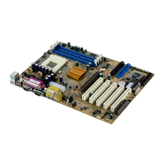
Introducing the Mainboard Congratulations on purchasing the K7S6A mainboard. The K7S6A mainboard is an ATX mainboard that uses a 4 -layer printed circuit board and measures 220 mm x 304 mm. The mainboard features a Socket 462 that accommodates AMD Athlon/Duron processors supporting frontside bus (FSB) speeds up to 100/133 MHz. -
Page 8: Features
1.0 GB (2 unbuffered DDR333 DIMM) or 1.5GB (3 unbuffered DDR266/DDR200 DIMM). The K7S6A includes a 4xAGP slot that provides four times the bandwidth of the original AGP specification. AGP technology provides a direct connection between the graphics sub-system and... - Page 9 (AC97 interface only) • Two IDE channels and a floppy disk drive interface The K7S6A supports Ultra DMA bus mastering with transfer rates of 33/66/100 MB/sec. Integrated I/O The mainboard has a full set of I/O ports and con- nectors: •...
- Page 11 Table of Mainboard Components Label Component AGP1 Accelerated Graphics Port ATX1 Power connector AUDIO Front Audio Connector Three volt realtime clock battery CASEFAN Case Fan header Primary CD-in connector Secondary CD-in connector CNR1 Communications Networking Riser slot CPU1 Socket A for AMD Athlon/Duron CPUs CPUFAN Cooling fan for CPU DDR1~DDR3...
-
Page 12: Choosing A Computer Case
There are many types of computer cases on the market. The mainboard complies with the specifications for the ATX sys- tem case. Some features on the mainboard are implemented by cabling connectors on the mainboard to indicators and switches on the system case. Ensure that your case supports all the features required. -
Page 13: Installing The Mainboard
Installing the Mainboard Follow these safety precautions when installing the mainboard: • Wear a grounding strip attached to a grounded device to avoid damage from static electricity. • Discharge static electricity by touching the metal case of a safely grounded object before working on the mainboard. -
Page 14: Quick Guide
This Quick Guide suggests the steps you can take to build your system with the mainboards. The following table describes installing specific components: Locating Mainboard Components Go to page 4 Installing Jumpers Go to page 9 Installing the Mainboard in a Case Go to page 13 Installing Case Components Go to page 14... -
Page 15: Checking Jumper Settings
This section explains how to set jumpers for correct configura- tion of the mainboard. Setting Jumpers Use the mainboard jumpers to set system configuration op- tions. Jumpers with more than one pin are numbered. When setting the jumpers, ensure that the jumper caps are placed on the correct pins. -
Page 16: Checking Jumper Settings
Checking Jumper Settings In the following illustration, pin 1 is shown. -
Page 17: Jumper Settings
Jumper Settings Jumper Type Description Setting (default) 3 pin Clear CMOS 1-2: Normal 2-3: Clear 3 pin KB wake-up 1-2: Enable function 2-3: Disable 2 pin BIOS protec- Open: Disable tion Short: Enable FIDJP 10 pin CPU ratio Refer to next FIDJP selector page... - Page 18 Clear CMOS Enables you to clear the BIOS: 1. Turn the system off. 2. Short pins 2 and 3 on jumper 1. 3. Return the jumper to the normal setting. 4. Turn the system on. The BIOS is returned to the default settings.
-
Page 19: Installing The Mainboard In A Case
Refer to the following illustration and instructions for installing the mainboard in a case: 2. Secure the screws in the This illustration shows mainboard holes that align an example of a main- with the chassis holes board being installed in a tower-type case: Note: Do not over- tighten the... -
Page 20: Connecting Case Components
After you have installed the mainboard into a case, you can begin connecting the mainboard components. Refer to the fol- lowing: 1. Connect the case power supply connector to ATX1. 2. Connect the CPU cooling fan cable to CPUFAN. 3. Connect the case cooling fan connector to either PWRFAN or CASFAN. -
Page 21: The Panel And Lpanel Connectors
The Panel and LPanel Connectors The panel connectors provide a set of switch and LED con- nectors found on ATX or Micro ATX cases. Select one from the two types of panel connector supported by this mainboard. PANEL Device Pins Empty Empty (Pin 10) -
Page 22: Installing Hardware
Installing the Processor Caution: When installing a CPU heatsink and cooling fan make sure that you DO NOT scratch the mainboard or any of the surface-mount resistors with the clip of the cooling fan. If the clip of the cooling fan scrapes across the m ain- board, you may cause serious damage to both the mainboard and the processor. -
Page 23: Cpu Installation Procedure
CPU Installation Procedure The following illustration shows CPU installation components: Follow these instructions to install the CPU: 1. Pull the CPU socket locking lever away from the socket to unhook it and raise the locking lever to the upright position. 2. - Page 24 6. Lower the CPU fan/heatsink unit onto the CPU and CPU socket and then snap the fan/heatsink into place. 7. Plug the CPU fan power cable into the CPU cooling fan power supply on the mainboard (CPUFAN).
-
Page 25: Install Memory Modules
Install Memory Modules This mainboard accommodates 184-pin 2.5V unbuffered Double Data Rate (DDR) SDRAM memory modules. The memory chips must be standard or registered SDRAM (Syn- chronous Dynamic Random Access Memory). This mainboard is capable of auto detecting the type of mem- ory modules (DDR SDRAM) you have installed and then automatically adjusting the voltage to the appropriate level. -
Page 26: Installation Procedure
Installation Procedure The mainboard accommodates three memory modules. You must install at least one module in any of the three slots. Each module can be installed with 32 MB to 512 MB of memory; to- tal memory capacity is 1.5 GB (PC200/PC266 DIMM) or 1.0 GB (PC333 DIMM). -
Page 27: Installing A Hard Disk Drive/Cd-Rom
3. Install the DIMM module into the slot and press it firmly down so that it seats correctly. The slot latches are levered upwards and latch on to the edges of the DIMM when it is installed correctly. Installing a Hard Disk Drive/CD-ROM This section describes how to install IDE devices such as a hard disk drive and a CD-ROM drive. -
Page 28: Installing A Hard Disk Drive
Installing a Hard Disk Drive 1. Install the hard disk drive into the drive cage in your system case. 2. Plug the IDE cable into IDE1 (A). Note: Ribbon cable connectors are usually keyed so that they can only be installed correctly on the device connector. - Page 29 Installing a CD-ROM/DVD Drive 1. Install the CD-ROM/DVD drive into the drive cage in your system case (A). 2. Plug the IDE cable into IDE1. If you have already in- stalled an HDD, you can use the free connector on its IDE cable (B).
-
Page 30: Installing A Floppy Diskette Drive
5. Plug a power cable from the case power supply into the power connector on the CD-ROM/DVD drive (C). When you first start up your system, the BIOS should auto- matically detect your CD-ROM/DVD drive. If it doesn’t, enter the Setup Utility and configure the CD-ROM/DVD drive that you have installed. -
Page 31: Installing Add-On Cards
pin-1 side of each ribbon cable is always marked with a colored stripe on the cable. 3. Plug one of the connectors on the FDD cable into the FDD connector (B). It doesn't matter which connector on the cable you use. Ensure that the pin-1 side of the cable is matched with the pin-1 side of the connector. - Page 32 1. Remove a blanking plate from the system case corre- sponding to the slot you are going to use. 2. Install the edge connector of the add-on card into the expansion slot. Ensure that the edge connector is cor- rectly seated in the slot. 3.
-
Page 33: Connecting Optional Devices
Connecting Optional Devices Refer to the following for information on connecting the main- board’s optional devices: AUDIO: Front Audio Connector This connector is used to attach to Audio equipment embed- ded into or attached to the case. - Page 34 Signal Name Signal Name AUD_MIC AUD_GND MIC_BIAS AUD_VCC AUD_F_R AUD_RET_R RESERVED EMPTY AUD_F_L AUD_RET_L LAUDIO: Mic/Speaker Out header Signal Name Signal Name Active LINE Out (R) Active LINE Out (L) GND (aLO) GND (aLO) GND (+12) GND (+12) +12V (1A) EMPTY GND (MIC) Front LINE Out(R)
- Page 35 LUSB2 Pin Assignment Signal Name Signal Name Ground USB4– Empty USB4+ USB5+ Ground USB5– Ground USB 2/3: USB panel connector The mainboard has USB ports installed on the rear edge I/O port array. However, some computer cases have a special module that mounts USB ports at the front of the case.
- Page 36 Signal Name 5VSB Ground SENSE If you have installed a modem, use the cable provided with the modem to plug into the mainboard WOM1 connector. This enables the Wake On Modem (WOM) feature. When your sys- tem is in a power-saving mode, any modem signal automatically resumes the system.
- Page 37 SPKR1: Internal speaker Connect the internal speaker connector to this header. Signal Name SPKR Ground SJ: Single color LED This connector is used to attach to devices that need a single color LED indicator. LSMI: System Management Interrupt This connector is for use with SMI hardware interrupt power management.
-
Page 38: Connecting I/O Devices
The backplane of the mainboard has a full set of I/O ports: Parallel port (LPT1) Game port PS/2 mouse PS/2 Serial port Serial port Microphone keyboard ports COM 1 COM 2 Line-in Line-out 1. Use the upper PS/2 port to connect a PS/2 pointing device. -
Page 39: External Connector Color Coding
External Connector Color Coding Many connectors now use standard colors as shown in the table below. Connector Color Analog VGA Blue Audio line-in Light blue Audio line-out Lime Digital monitor / flat panel White IEEE 1394 Grey Microphone Pink MIDI/Game Gold Parallel Burgundy... -
Page 40: Using Bios
Using BIOS The computer uses the latest Award BIOS with support for Windows Plug and Play. The CMOS chip on the mainboard contains the ROM setup instructions for configuring the main- board BIOS. The BIOS (Basic Input and Output System) Setup Utility dis- plays the system's configuration status and provides you with options to set system parameters. -
Page 41: The Standard Configuration
The Standard Configuration A standard configuration has already been set in the Setup Utility. However, we recommend that you read this chapter in case you need to make any changes in the future. This Setup Utility should be used: • when changing the system configuration •... -
Page 42: Entering The Setup Utility
Entering the Setup Utility When you power on the system, BIOS enters the Power-On Self Test (POST) routines. POST is a series of built-in diag- nostics performed by the BIOS. After the POST routines are completed, the following message appears: Press DEL to enter SETUP Pressing the delete key accesses the BIOS Setup Utility:... -
Page 43: Updating The Bios
Updating the BIOS You can download and install updated BIOS for this main- board from the manufacturer's web site. New BIOS provides support for new peripherals, improvements in performance, or fixes for known bugs. Install new BIOS as follows: 1. If your mainboard has a BIOS protection jumper, change the setting to allow BIOS flashing. -
Page 44: Using Bios
When you start the Setup Utility, the main menu appears. The main menu of the Setup Utility displays a list of the options that are available. A highlight indicates which option is cur- rently selected. Use the cursor arrow keys to move the highlight to other options. -
Page 45: Date And Time
Date and Time The Date and Time items show the current date and time on the computer. If you are running a Windows OS, these items are automatically updated whenever you make changes to the Windows Date and Time Properties utility. IDE Devices (None) Your computer has two IDE channels (Primary and Secondary) and each channel can be installed with one or two devices... - Page 46 Refer to your drive's documentation or look on the drive casing if you need to obtain this information. If no device is installed, change the value to None. Note: Before attempting to configure a hard disk drive, ensure that you have the configuration information supplied by the manufacturer of your hard drive.
-
Page 47: Advanced Bios Setup Option
Advanced BIOS Setup Option This option displays a table of items that define advanced in- formation about your system. CMOS Setup Utility – Copyright (C) 1984 – 2001 Award Software Advanced BIOS Features Item Help Anti-Virus Protection [Disabled ] CPU Internal Cache [Enabled] Menu Level External Cache... - Page 48 External Cache (Enabled) Most processors that can be installed in this system use e x- ternal level 2 (L2) cache memory to improve performance. Leave this item at the default value for better performance. Quick Power On Self Test (Enabled) Enable this item to shorten the power on testing (POST) and have your system start up faster.
- Page 49 Typematic Rate Setting (Disabled) If this item is enabled, you can use the following two items to set the typematic rate and the typematic delay settings for your keyboard. • Typematic Rate (Chars/Sec): Use this item to define how many characters per second are generated by a held-down key.
- Page 50 Windows 95, select Yes for this item to ensure compatibility with the Windows 95 logo certification. Otherwise, select No. Video BIOS Shadow (Enabled) When set to Enabled, the system copies the VGA BIOS into system DRAM. Small Logo (EPA) Show (Disabled) Enables or disables the display of the EPA logo during boot.
-
Page 51: Advanced Chipset Features Option
Advanced Chipset Features Option This option displays a table of items that define critical timing parameters of the mainboard. You should leave the items on this page at their default values unless you are very familiar with the technical specifications of your system hardware. If you change the values incorrectly, you may introduce fatal er- rors or recurring instability into your system. -
Page 52: Advanced Dram Control
Advanced DRAM Control 1 Scroll to this item and press <Enter> to view the following screen: CMOS Setup Utility – Copyright (C) 1984 – 2001 Award Software Advanced DRAM Control 1 Item Help Auto configuration [Normal Mode] CPU/DRAM CLK Synch CTL [Auto] Menu Level DRAM BackGround Cycles... - Page 53 Advanced DRAM control 2 Scroll to this item and press <Enter> to view the following screen: CMOS Setup Utility – Copyright (C) 1984 – 2001 Award Software Advanced DRAM Control 2 Item Help CS[5:0]# Hold Time CTL [+0.5 ns] DQS/CSB Hold Time CTL [+0.5 ns] Menu Level CKE Hold Time CTL...
-
Page 54: Integrated Peripherals Option
AGP Data Transfer Rates (Support 4X) Determines the data transfer rate of AGP data at either 4X or 2X depending on your Advanced Graphics Card. AGP Aperture Size (64MB) This item defines the size of the aperture if you use an AGP graphics adapter. - Page 55 SIS OnChip IDE Device Scroll to this item and press <Enter> to view the following screen: CMOS Setup Utility – Copyright (C) 1984 – 2001 Award Software SIS OnChip IDE Device Item Help Internal PCI/IDE [Both] Primary Master [Auto] Menu Level Primary Slave [Auto] Secondary Master PIO...
- Page 56 tions then burst onto the PCI bus and nonburstable transac- tions do not. Press <Esc> to return to the Integrated Peripherals screen. SIS OnChip PCI Device Scroll to this item and press <Enter> to view the following screen: CMOS Setup Utility – Copyright (C) 1984 – 2001 Award Software SIS OnChip PCI Device Item Help SIS-7012/7018 AC97Audio...
- Page 57 AC97 ACCESS INTERFACE (PCI BUS) This option determines whether the AC’ 97 interface uses an embedded bus or a PCI bus Press <Esc> to return to the Integrated Peripherals screen. Onboard SuperIO Device Scroll to this item and press <Enter> to view the following screen: CMOS Setup Utility –...
- Page 58 baud rate up to 57.6K bps. UR2 Duplex Mode (Half) This field is available when UART 2 Mode is set to either ASKIR or IrDA. This item enables you to determine the infra- red (IR) function of the onboard infrared chip. The options are Full and Half (default).
-
Page 59: Power Management Setup Option
ports on this mainboard. USB Keyboard Support (Disabled) Enable this item if you plan to use a keyboard connected through the USB port in a legacy operating system (such as DOS) that does not support Plug and Play. IDE HDD Block Mode (Enabled) Enable this field if your IDE hard drive supports block mode. - Page 60 Wake Up Calls If the system is suspended, or has been powered down by software, it can be resumed by a wake up call that is gener- ated by incoming traffic to a modem, a LAN card, a PCI card, or a fixed alarm on the system realtime clock, CMOS Setup Utility –...
- Page 61 Video Off Option (Suspend --> Off) This option defines if the video is powered down when the system is put into suspend mode. Video Off Method (DPMS Support) This item defines how the video is powered down to save power. This item is set to DPMS (Display Power Management Software) by default.
- Page 62 Under ACPI (Advanced Configuration and Power manage- ment Interface) you can create a software power down. In a software power down, the system can be resumed by Wake Up Alarms. This item lets you install a software power down that is controlled by the normal power button on your system. If the item is set to Instant-Off, then the power button causes a software power down.
-
Page 63: Pm Wake Up Events
PM Wake Up Events Scroll to this item and press <Enter> to view the following screen: CMOS Setup Utility – Copyright (C) 1984 – 2000 Award Software PM Wake Up Events Item Help IRQ [3-7, 9-15], NMI [Enabled ] IRQ 8 Break suspend [Disabled] Menu Level Ring Power Up Control... -
Page 64: Pnp/Pci Configuration Option
alarm will power on your system every day at the specified time. PNP/PCI Configuration Option This option displays a table of items that configures how PnP (Plug and Play) and PCI expansion cards operate in your sys- tem. Both the ISA and PCI buses on the Mainboard use system IRQs (Interrupt ReQuests) and DMAs (Direct Memory Access). - Page 65 In the IRQ Resources submenu, if you change any of the IRQ assignations to Legacy ISA, then that Interrupt Request Line is reserved for a legacy ISA expansion card. Press <Esc> to close the IRQ Resources submenu. In the Memory Resources submenu, use the first item R e- served Memory Base to set the start address of the memory you want to reserve for the ISA expansion card.
-
Page 66: Pci Health Status Option
PCI Health Status Option On mainboards that support hardware monitoring, this item lets you monitor the parameters for critical voltages, critical temperatures, and fan speeds. You cannot make any changes to these fields. They are display only: CMOS Setup Utility – Copyright (C) 1984 – 2001 Award Software PC Health Status Item Help Shutdown Temperature... -
Page 67: Frequency/Voltage Control
Frequency/Voltage Control This item enables you to set the clock speed and system bus for your system. The clock speed and system bus are deter- mined by the kind of processor you have installed in your system. CMOS Setup Utility – Copyright (C) 1984 – 2001 Award Software Frequency/Voltage Control Item Help Auto Detect DIMM/PCI Clk... -
Page 68: Load Fail-Safe Defaults Option
Load Fail-Safe Defaults Option This option opens a dialog box that lets you install fail-safe de- faults for all appropriate items in the Setup Utility: Press <Y> and then <Enter> to install the defaults. Press <N> and then <Enter> to not install the defaults. The fail-safe de- faults place no great demands on the system and are generally stable. -
Page 69: Set Password Option
Set Password Option This item can be used to install a password. To install a pass- word, follow these steps: 1. Highlight the item Set Password on the main menu and press <Enter>. 2. The password dialog box appears. Enter Password: 3. -
Page 70: Save & Exit Setup Option
Save & Exit Setup Option Highlight this item and press <Enter> to save the changes that you have made in the Setup Utility and exit the Setup Utility. When the Save and Exit dialog box appears, press <Y> to save and exit, or press <N> to return to the main menu: Exit Without Saving Highlight this item and press <Enter>... -
Page 71: Using The Mainboard Software
Using the Mainboard Software The support software CD-ROM that is included in the main- board package contains all the drivers and utility programs needed to properly run the bundled products. Below you can find a brief description o f each software program, and the lo- cation for your mainboard version. -
Page 72: Auto-Installing Under Windows 98
The Auto-install CD-ROM makes it easy for you to install the drivers and software for your mainboard. Note: If the Auto-install CD-ROM does not work on your system, you can still install drivers through the file manager for your OS (for example, Windows Ex- plorer). -
Page 73: Running Setup
Browse CD The Browse CD button is the standard Windows command that allows you to open Windows Explorer and show the con- tents of the support CD. Before installing the software from Windows Explorer, look for a file named README.TXT, INSTALL.TXT or something simi- lar. - Page 74 Note: The following screens are examples only. The screens and driver lists will be different according to the mainboard you are installing. The mainboard identification is located in the upper left-hand corner. 2. Click Next. The following screen appears: 3. Check the box next to the items you want to install. The default options are recommended.
-
Page 75: Manual Installation
Insert the CD in the CD-ROM drive and locate the PATH.DOC file in the root directory. This file contains the information needed to locate the drivers for your mainboard. Look for the chipset and mainboard model; then browse to the directory and path to begin installing the drivers. -
Page 76: Recovery Genius
PC-CILLIN The PC-CILLIN software program provides anti-virus protec- tion for your system. This program is available for Windows 2000/ME/98SE and Windows NT. Be sure to check the r e - adme.txt and install the appropriate anti-virus software for your operating system. We strongly recommend users to install this free anti-virus software to help protect your system against viruses. - Page 77 from virus intrusion, accidental deletions, and system corrup- tion. To install the Recovery Genius software program run SETUP.EXE from the following directory \UTILITY\RECOVERY GENIUS\ENG\RECOVERYGENIUS Language Genius The Language Genius is a software-based product that helps you to learn new languages. To install the Language Genius software program run SETUP.EXE from the following directory \UTILITY\LANGUAGE GENIUS\ENG\LANGUAGEGENIUS PageABC...
-
Page 78: Setting Jumpers
Setting Jumpers Jumper Settings Jumper Type Description Setting (default) 3 pin Clear CMOS 1-2: Normal 2-3: Clear 3 pin KB wake-up 1-2: Enable function 2-3: Disable 2 pin BIOS protec- Open: Disable tion Short: Enable FIDJP 10 pin CPU ratio Refer to next FIDJP selector... - Page 79 Clear CMOS Enables you to clear the BIOS: 1. Turn the system off. 2. Short pins 2 and 3 on jumper 1. 3. Return the jumper to the normal setting. 4. Turn the system on. The BIOS is returned to the default settings.
-
Page 80: The Panel And Lpanel Connectors
The Panel and LPanel Connectors The panel connectors provide a set of switch and LED con- nectors found on ATX or Micro ATX cases. Select one from the two types of panel connector supported by this mainboard. PANEL Device Pins Empty Empty (Pin 10)
Need help?
Do you have a question about the K7S6A and is the answer not in the manual?
Questions and answers