Table of Contents
Advertisement
Copyright
This publication, including all photographs, illustrations and software, is protected un-
der international copyright laws, with all rights reserved. Neither this manual, nor any
of the material contained herein, may be reproduced without written consent of the au-
thor.
Version 3.1b
Disclaimer
The information in this document is subject to change without notice. The manufac-
turer makes no representations or warranties with respect to the contents hereof and
specifically disclaims any implied warranties of merchantability or fitness for any par-
ticular purpose. The manufacturer reserves the right to revise this publication and to
make changes from time to time in the content hereof without obligation of the manu-
facturer to notify any person of such revision or changes.
Trademark Recognition
Microsoft, MS-DOS and Windows are registered trademarks of Microsoft Corp.
MMX, Pentium, Pentium-II, Pentium-III, Celeron are registered trademarks of Intel
Corporation.
Other product names used in this manual are the properties of their respective owners
and are acknowledged.
Federal Communications Commission (FCC)
This equipment has been tested and found to comply with the limits for a Class B digi-
tal device, pursuant to Part 15 of the FCC Rules. These limits are designed to provide
reasonable protection against harmful interference in a residential installation. This
equipment generates, uses, and can radiate radio frequency energy and, if not in-
stalled and used in accordance with the instructions, may cause harmful interference
to radio communications. However, there is no guarantee that interference will not oc-
cur in a particular installation. If this equipment does cause harmful interference to
radio or television reception, which can be determined by turning the equipment off
and on, the user is encouraged to try to correct the interference by one or more of the
following measures:
−
Reorient or relocate the receiving antenna.
−
Increase the separation between the equipment and the receiver.
−
Connect the equipment onto an outlet on a circuit different from that to which
the receiver is connected.
−
Consult the dealer or an experienced radio/TV technician for help.
Shielded interconnect cables and a shielded AC power cable must be employed with
this equipment to ensure compliance with the pertinent RF emission limits governing
this device. Changes or modifications not expressly approved by the system's manu-
facturer could void the user's authority to operate the equipment.
Preface
Advertisement
Table of Contents

Related Manuals for ECS K7S5A


Summary of Contents for ECS K7S5A
- Page 1 Preface Copyright This publication, including all photographs, illustrations and software, is protected un- der international copyright laws, with all rights reserved. Neither this manual, nor any of the material contained herein, may be reproduced without written consent of the au- thor.
- Page 2 Declaration of Conformity This device complies with part 15 of the FCC rules. Operation is subject to the follow- ing conditions: − This device may not cause harmful interference, and − This device must accept any interference received, including interference that may cause undesired operation.
-
Page 3: Table Of Contents
Preface Features and Packing List Translations ¿ ù » ~ ! © | ¥ ¼ © w ¸ q ® Ñ Å Ò ¡ C CHAPTER 1 Introducing the Mainboard Introduction....................1 Checklist ....................1 Standard Items ....................1 Features ....................2 Choosing a Computer Case............... - Page 4 Load Optimal Settings ................... 28 Load Best Performance Settings..............28 Features Setup Page..................28 CPU PnP Setup Page ..................30 Hardware Monitor Page................. 31 Change Password................... 32 Change or Remove the Password ..............32 Exit ........................ 32 CHAPTER 4 Using the Mainboard Software About the Software CD-ROM..............
-
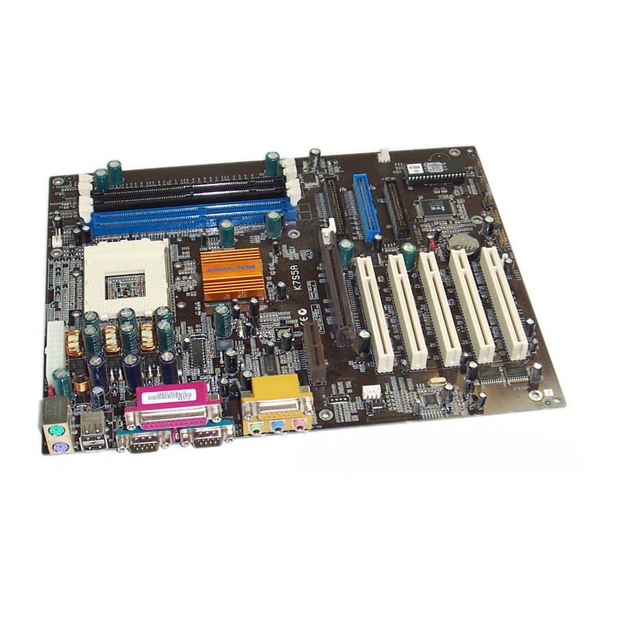
Page 5: Introducing The Mainboard
Introducing the Mainboard Congratulations on purchasing the K7S5A mainboard. This mainboard has a Socket-A processor socket for the type of AMD K7 processors. You can install any one of these processors on the mainboard. The mainboard supports front- side bus speeds of 200/266MHz. -
Page 6: Features
• Supports AMD Athlon XP/Athlon/Duron processors Processor • Supports 200/266 MHz Front-Side Bus Note: Processors are automatically configured using firmware and a synchronous Host/DRAM Clock Scheme. • Two 168-pin DIMM slots for SDRAM memory modules Memory • Two 184-pin DIMM slots for DDR memory modules •... -
Page 7: Choosing A Computer Case
Onboard Flash Supports Plug and Play configuration of peripheral devices and expansion cards Dimensions ATX form factor (30.5cm x 24.4cm) There are many types of computer cases on the market. The mainboard com- plies with the specifications for the ATX system case. Some features on the mainboard are implemented by cabling connectors on the mainboard to indi- cators and switches on the system case. -
Page 9: Installing The Mainboard
Installing the Mainboard Follow these safety precautions when installing the mainboard: • Wear a grounding strap attached to a grounded device to avoid damage from static electricity. • Discharge static electricity by touching the metal case of a safely grounded object before working on the mainboard. •... -
Page 10: Installing The Mainboard In A Case
Refer to the following illustration and instructions for installing the mainboard in a case: This illustration shows an ex- 2. Secure the mainboard with ample of a mainboard being screws where appropriate. installed in a tower-type case: Note: Do not overtighten the screws as this can stress the main- board. -
Page 11: Checking Jumper Settings
Checking Jumper Settings The following illustration shows the location of the mainboard jumpers. Pin 1 is labeled. Jumper Settings Jumper Type Description Setting (default) 3-pin Keyboard Power 1-2: Disable Key- On Selector board Power On 2-3: Enable Key- board Power On 3-pin Clear CMOS 1-2: Clear CMOS... -
Page 12: Connecting Case Components
nect all the power cables from the mainboard and then move the jumper cap into the CLEAR setting for a few seconds. After you have installed the mainboard into a case, you can begin connecting the mainboard components. Refer to the following: Connect the power connector from the power supply to the... -
Page 13: The Fpi Connector
Signal Name Link LED Ground 10/100 Mbps mode LED The FPI Connector This panel connector provides a set of switch and LED connectors found on ATX case. Refer to the table below for information. Signal Name Function HD_LED_P Hard disk LED (positive) FP PWR/SLP MSG LED [dual color or single color (+)] HD_LED_N... -
Page 14: Installing Hardware
Installing the Processor Caution: When installing a CPU heatsink and cooling fan make sure that you DO NOT scratch the mainboard or any of the surface-mount resistors with the clip of the cooling fan. If the clip of the cooling fan scrapes across the mainboard, you may cause serious damage to the mainboard or its components. -
Page 15: Cpu Installation Procedure
CPU Installation Procedure The following illustration shows CPU installation components: Note: The pin-1 corner is marked with an arrow Follow these instructions to install the CPU: Pull the CPU socket locking lever away from the socket to unhook it and raise the locking lever to the upright position. -
Page 16: Installing Memory Modules
Connect the CPU Cooling Fan power cable connector to the CPUFAN connector. • To achieve better airflow rates and heat dissipation, we suggest that Notes: you use a high quality fan with 4800 rpm at least. • CPU fan and heatsink installation procedures may vary with the type of CPU fan/heatsink supplied. -
Page 17: Installing A Hard Disk Drive/Cd-Rom
Check that the cutouts on the DIMM module edge connector match the notches in the DIMM slot: Latch Latch Cutout Cutouts Notch Notches Latch Latch DDR SDRAM Module SDRAM Module Install the DIMM module into the slot and press it firmly down until it seats correctly. -
Page 18: Installing A Hard Disk Drive
Installing a Hard Disk Drive Install the hard disk drive into the drive cage in your system case. Plug the IDE cable into IDE1 (A): Note: Ribbon cable connectors are usually keyed so that they can only be installed correctly on the device connector. -
Page 19: Installing A Floppy Diskette Drive
Installing a Floppy Diskette Drive The mainboard has a floppy diskette drive (FDD) interface and ships with a diskette drive ribbon cable that supports one or two floppy diskette drives. You can install a 5.25-inch drive and a 3.5-inch drive with various capacities. The floppy diskette drive cable has one type of connector for a 5.25-inch drive and another type of connector for a 3.5-inch drive. - Page 20 AGP Slot The AGP slot is used to install a graphics adapter that supports the 4xAGP specifications and has a 4xAGP edge connector. Note: The above layout is for reference only. The AGP slot may be different from your mainboard. Please refer to actual shipment.
-
Page 21: Connecting Optional Devices
Connecting Optional Devices Refer to the following for information on connecting the mainboard’s optional devices: FP_AUD1O: Front panel MIC/Speaker Out header This header allows the user to install auxiliary front-oriented microphone and line-out ports for easier access. Signal Name Signal Name AUD_MIC AUD_GND AUD_MIC_BIAS... - Page 22 USB1: Extended USB header The mainboard has USB ports installed on the rear edge I/O port array. Some computer cases have a special module that mounts USB ports at the front of the case. If you have this kind of case, use auxiliary USB connectors USB1 to connect the front-mounted ports to the mainboard.
-
Page 23: Connecting I/O Devices
The backplane of the mainboard has the following I/O ports: Parallel port (LPT1) Game port PS/2 port mouse PS/2 Serial port Serial port Microphone keyboard ports COM 1 COM 2 Line-in Line-out PS/2 Mouse Use the upper PS/2 port to connect a PS/2 point- ing device. -
Page 24: External Connector Color Coding
External Connector Color Coding Many connectors now use standard colors as shown in the table below. Connector Color Audio line-in Light blue Audio line-out Lime Digital monitor/flat panel White IEEE 1394 Grey Microphone Pink MIDI/game Gold Parallel Burgundy PS/2-compatible keyboard Purple PS/2-compatible mouse Green... -
Page 25: Using Bios
Using BIOS The computer uses the latest AMI BIOS with support for Windows Plug and Play. The CMOS chip on the mainboard contains the ROM setup instructions for configuring the mainboard BIOS. The BIOS (Basic Input and Output System) Setup Utility displays the system's configuration status and provides you with options to set system parameters. -
Page 26: Running The Setup Utility
Running the Setup Utility Each time your computer starts, before the operating system loads, a mes- sage appears on the screen that prompts you to “Hit <DEL> if you want to run SETUP”. When you see this message, press the Delete key and the Main menu page of the Setup Utility appears on your monitor. -
Page 27: Standard Cmos Features
to change the values for the option. Use the cursor arrow keys to scroll through the items in the submenu. In this manual, default values are enclosed in parenthesis. Submenu items are denoted by a triangle Standard CMOS Features Use this page to set basic information such as the date, the time, the IDE de- vices, and the diskette drives. -
Page 28: Advanced Setup Page
Advanced Setup Page Use this page to set more advanced information about your system. Take some care with this page. Making changes can affect the operation of your computer. AMIBIOS SETUP – ADVANCED SETUP (C) 2000 American Megatrends, Inc. All Rights Reserved Quick Boot Enabled Boot Device... - Page 29 Floppy Drive Seek If you enable this item, your system will check all floppy disk drives at start up. Disable this item unless you are using an old 360KB drive. Password Check If you have entered a password for the system, use this item to determine if the password is required to enter the Setup Utility (Setup) or required both at start-up and to enter the Setup Utility (Always).
-
Page 30: Power Management Setup Page
Power Management Setup Page This page sets some of the parameters for system power management opera- tion. AMIBIOS SETUP – POWER MANAGEMENT SETUP (C) 2000 American Megatrends, Inc. All Rights Reserved ACPI Aware O/S Power Management Enabled Suspend Time Out Disabled Hard Disk Time Out Disabled... -
Page 31: Pci / Plug And Play Setup
KeyBoard Power On Function If you enable this item, you can turn the system on and off by pressing hot keys on the keyboard. You must enable the Keyboard Power On jumper and use an ATX power supply in order to use this feature. Power On by LAN Your system can enter a software power down. -
Page 32: Load Optimal Settings
Load Optimal Settings If you select this item and press Enter a dialog box appears. If you press Y, and then Enter, the Setup Utility loads a set of fail-safe default values. These default values are not very demanding and they should allow your system to function with most kinds of hardware and memory chips. - Page 33 Onboard Parallel Port Use this item to enable or disable the onboard LPT1 parallel port, and to as- sign a port address. The Auto setting will detect and available address. Parallel Port Mode Use this item to set the parallel port mode. You can select SPP (Standard Parallel Port), ECP (Extended Capabilities Port), EPP (Enhanced Parallel Port), or ECP + EPP.
-
Page 34: Cpu Pnp Setup Page
CPU PnP Setup Page This page lets you manually configure the mainboard for the CPU. The system will automatically detect the kind of CPU that you have installed and make the appropriate adjustments to the items on this page. AMIBIOS SETUP – CPU PnP Setup Page (C) 2000 American Megatrends, Inc. -
Page 35: Hardware Monitor Page
Hardware Monitor Page This page sets some of the parameters for the hardware monitoring function of this mainboard. AMIBIOS SETUP – Hardware Monitor Page (C) 2000 American Megatrends, Inc. All Rights Reserved --- System Hardware --- Vcore 2.000 V Vcc2.5V 2.500 V Vcc3.3V 3.300 V... -
Page 36: Change Password
Change Password If you highlight this item and press Enter, a dialog box appears which lets you enter a Supervisor password. You can enter no more than six letters or num- bers. Press Enter after you have typed in the password. A second dialog box asks you to retype the password for confirmation. -
Page 37: Using The Mainboard Software
Using the Mainboard Software The support software CD-ROM that is included in the mainboard package contains all the drivers and utility programs needed to properly run the bun- dled products. Below you can find a brief description of each software program, and the location for your mainboard version. -
Page 38: Running Setup
Setup Tab Setup Click the Setup button to run the software installation program. Select from the menu which software you want to install. Browse The Browse CD button is the standard Windows command that allows you to open Windows Explorer and show the contents of the support CD. -
Page 39: Manual Installation
Note: The following screens are examples only. The screens and driver lists will be different according to the mainboard you are installing. The mainboard identification is located in the upper left-hand corner. Click Next. The following screen appears: Check the box next to the items you want to install. The default options are recommended. -
Page 40: Utility Software Reference
Insert the CD in the CD-ROM drive and locate the PATH.DOC file in the root directory. This file contains the information needed to locate the drivers for your mainboard. Look for the chipset and mainboard model; then browse to the directory and path to begin installing the drivers. -
Page 41: Recovery Genius
MediaRing Talk – Telephony Software To install the MediaRing Talk voice modem software for the built-in modem, go directory \UTILITY\MEDIARING TALK, then MRTALK- SETUP72.EXE to install the application software. Super Voice – Fax/Modem Software To install the Super Voice voice, fax, data communication application for use with the built-in fax/modem, go the directory \UTILITY\SUPER_VOICE, then run PICSHELL.EXE to install the application software.
Need help?
Do you have a question about the K7S5A and is the answer not in the manual?
Questions and answers