Table of Contents
Advertisement
Mainboard User's Manual
This publication, including all photographs, illustrations and
software, is protected under international copyright laws, with all
rights reserved. Neither this manual, nor any of the material
contained herein, may be reproduced without the express written
consent of the manufacturer.
The information in this document is subject to change without
notice. The manufacturer makes no representations or warranties
with respect to the contents hereof and specifically disclaims any
implied warranties of merchantability or fitness for any particular
purpose. Further, the manufacturer reserves the right to revise this
publication and to make changes from time to time in the content
hereof without obligation of the manufacturer to notify any person
of such revision or changes.
Trademarks
IBM, VGA, and PS/2 are registered trademarks of International
Business Machines.
AMD is registered trademark of Advanced Micro Devices Inc.
Intel, Pentium/II/III, Celeron and MMX are registered trademarks
of Intel Corporation.
Microsoft, MS-DOS and Windows NT/95/98/ME/2000 are
registered trademarks of Microsoft Corporation.
PC-cillin and ChipAwayVirus are registered trademarks of Trend
Micro Inc.
AMI is a registered trademark of American Megatrends Inc.
A3D is a registered trademark of Aureal Inc.
MediaRing Talk is a registered trademark of MediaRing Inc.
3Deep is a registered trademark of E-Color Inc.
SiS is a trademark of Silicon Integrated System Corporation.
Other names used in this publication may be trademarks and are
acknowledged.
Copyright © 2001
All Rights Reserved
K7S5A, V1.0
June, 2001
Advertisement
Table of Contents

Related Manuals for ECS K7S5A


Summary of Contents for ECS K7S5A
- Page 1 MediaRing Talk is a registered trademark of MediaRing Inc. 3Deep is a registered trademark of E-Color Inc. SiS is a trademark of Silicon Integrated System Corporation. Other names used in this publication may be trademarks and are acknowledged. Copyright © 2001 All Rights Reserved K7S5A, V1.0 June, 2001...
- Page 2 Mainboard User’s Manual Notice for DDR SDRAM: The table below lists the model chips of DDR that we have tested. We will test more DDR modules in the future. Model Chip Memory Manufacture K4H2808388-TCBO 128 M Sams ung HY5DU28822T-H 128 M Hyundai 46V8M8-75M 128 M...
-
Page 3: Table Of Contents
Mainboard User’s Manual Table of Contents Trademar ks................ I Chapter 1 ..................1 Introduction ................1 Key Features..............2 Package Contents ...............5 Static Electricity Precautions ..........6 Pre-Installation Inspection...........6 Chapter 2 ..................7 Mainboard Installation ............7 Mainboard Components............8 I/O Ports................8 Install A CPU..............9 Install Memory ..............10 Setting Jumper Switches ...........12 Install the Mainboard............ - Page 4 Mainboard User’s Manual Utility Folder Installation Notes.........36 Mainboard (K7S5A) Installation Notes ......37...
-
Page 5: Chapter 1
1: Introduction Chapter 1 Introduction This mainboard has a Socket-A processor socket for an AMD K7 type processors. You can install any one of these processors on the mainboard. The mainboard supports front-side bus speeds of 200/266MHz. This mainboard uses the SiS 735 chipset which supports a 4X AGP slot for highly graphics display, DDR interface and Ultra DMA 33/66/100 function, provides outstanding high system performance under all types of system operations. -
Page 6: Key Features
Mainboard User’s Manual Key Features The key features of this mainboard include: Socket-A Processor Support Supports AMD Athlon/Duron processors Supports 200/266 MHz Front-Side Bus Processors are automatically configured using firmware and a synchronous Host/DRAM Clock Scheme. Memory Support Two 168-pin DIMM slots for SDRAM memory modules Two 184-pin DIMM slots for DDR memory modules Support SDRAM up to 133 MHz /DDR up to 266 MHz memory bus... - Page 7 1: Introduction AC97 Codec ♦ Compliant AC97 2.1 specification ♦ Supports 18-bit ADC (Analog Digital Converter) and DAC (Digital Analog Converter) as well as 18 -bit stereo full- duplex codec Built-in Ethernet LAN (Optional) ♦ Built-in 10BaseT/100BaseTX Ethernet LAN ♦ LAN controller integrates Fast Ethernet MAC and PHY compliant with IEEE802.3u 100BASE-TX, 10BASE-T and ANSI X3.263 TP-PMD standards ♦...
- Page 8 Mainboard User’s Manual Bundled Software ♦ PC-Cillin2000 provides automatic virus protection under Windows 95/98/NT/2000 ♦ MediaRing Talk provides PC to PC or PC to Phone internet phone communication ♦ WinDVD2000 is a DVD playback application (optional) Dimensions ♦ ATX form factor (30.5cm x 24.4cm)
-
Page 9: Package Contents
1: Introduction Package Contents Your mainboard package ships with the following items: The mainboard This User’s Guide 1 UDMA/66 IDE cable 1 Floppy disk drive cable Support software on CD-ROM disk Optional Accessories You can purchase the following optional accessories for this mainboard. -
Page 10: Static Electricity Precautions
Mainboard User’s Manual Static Electricity Precautions Components on this mainboard can be damaged by static electricity. Take the following precautions when unpacking the mainboard and installing it in a system. 1. Keep the mainboard and other components in their original static-proof packaging until you are ready to install them. -
Page 11: Chapter 2
2: Mainboard Installation Chapter 2 Mainboard Installation To install this mainboard in a system, follow the procedures in this chapter: Identify the mainboard components Install a CPU Install one or more system memory modules Verify that any jumpers or switches are set correctly Install the mainboard in a system chassis (case) Connect any extension brackets or cables to the mainboard connector headers... -
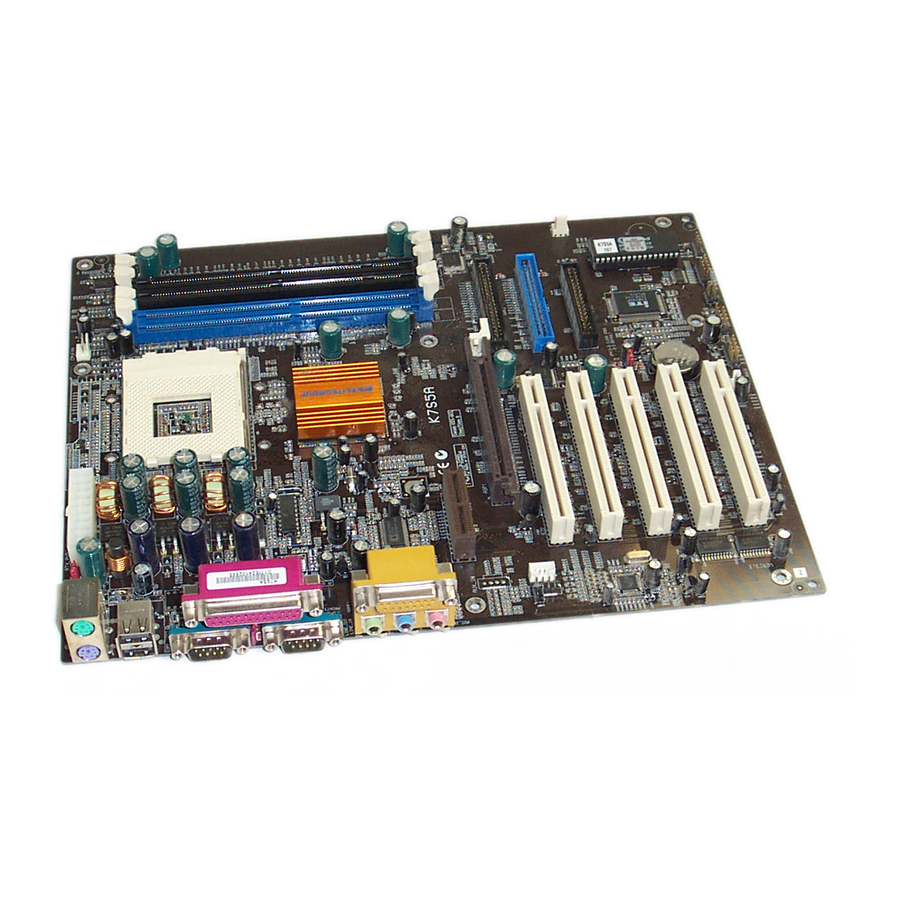
Page 12: Mainboard Components
Mainboard User’s Manual Mainboard Components Use the diagram below to identify the major components on the mainboard. Note: Any jumper on your mainboard that do not appear in the illustration above is for testing only. I/O Ports The illustration below shows a side view of the built-in I/O ports on the mainboard. -
Page 13: Install A Cpu
2: Mainboard Installation Install A CPU This mainboard has a Socket-A which supports AMD K7 processors. To ensure reliability, ensure that your processor has a heatsink/cooling fan assembly. Do not try to install a Socket-370/Socket-7 processor in the Socket- 462. A Socket-370/Socket-7 processor such as the PPGA Celeron, FCPGA Pentium-III, Pentium-MMX, or the AMD K5/K6 does not fit in the Socket-462. -
Page 14: Install Memory
Mainboard User’s Manual 4. Match the Pin-1 corners and insert the processor into the socket. No force is required and the processor should drop into place freely. 5. Swing the locking lever down and hook it under the catch on the side of the socket. - Page 15 2: Mainboard Installation To install a module, push the retaining latches at either end of the socket outwards. Position the memory module correctly and insert it into the DIMM socket. Press the module down into the socket so that the retaining latches rotate up and secure the module in place by fitting into notches on the edge of the module.
-
Page 16: Setting Jumper Switches
Mainboard User’s Manual Setting Jumper Switches Jumpers are sets of pins which can be connected together with jumper caps. The jumper caps change the way the mainboard operates by changing the electronic circuits on the mainboard. If a jumper cap connects two pins, we say the pins are SHORT. If a jumper cap is removed from two pins, the pins are OPEN. - Page 17 2: Mainboard Installation Jumper JP4: Clear CMOS Memory Use this jumper to clear the contents of the CMOS memory. You may need to clear the CMOS memory if the settings in the Setup Utility are incorrect and prevent your mainboard from operating. To clear the CMOS memory, disconnect all the power cables from the mainboard and then move the jumper cap into the CLEAR setting for a few seconds.
-
Page 18: Install The Mainboard
Mainboard User’s Manual Install the Mainboard Install the mainboard in a system chassis (case). The board is an ATX size mainboard with a twin-tier of I/O ports. You can install this mainboard in an ATX case. Ensure that your case has an I/O cover plate that matches the ports on this mainboard. -
Page 19: Optional Extension Brackets
2: Mainboard Installation Optional Extension Brackets For this mainboard, you can also obtain a USB module extension bracket for more USB ports. Install them by following the steps below. Note: All the ribbon cables used on the extension brackets have a red stripe on the Pin-1 side of the cable. -
Page 20: Install Other Devices
Mainboard User’s Manual Install Other Devices Install and connect any other devices in the system following the steps below. IDE1 Floppy Disk Drive The mainboard ships with a floppy disk drive cable that can support one or two drives. Drives can be 3.5” or 5.25” wide, with capacities of 360K, 720K, 1.2MB, 1.44MB, or 2.88MB. - Page 21 2: Mainboard Installation Internal Sound Connections If you have installed a CD-ROM drive or DVD-ROM drive, you can connect the drive audio cable to the onboard sound system. On the mainboard, locate the two 4-pin connectors CD1 and CD2. There are two kinds of connector because different brands of CD- ROM drive have different kinds of audio cable connectors.
-
Page 22: Expansion Slots
Mainboard User’s Manual Expansion Slots This mainboard has five 32-bit PCI slots, one AGP slot and one AMR slot. PCI5 PCI3 PCI1 AGP1 PCI4 PCI2 Follow the steps below to install a PCI/AGP/AMR expansion card. 1. Locate the AMR, AGP or PCI slots on the mainboard. 2. -
Page 23: Chapter 3
3: BIOS Setup Utility Chapter 3 BIOS Setup Utility Introduction The BIOS Setup Utility records settings and information about your computer such as the date and time, the kind of hardware installed, and various configuration settings. Your computer uses this information to initialize all the components when booting up and functions as the basis for coordination between system components. -
Page 24: Running The Setup Utility
Mainboard User’s Manual Running the Setup Utility Each time your computer starts, before the operating system loads, a message appears on the screen that prompts you to “Hit <DEL> if you want to run SETUP”. When you see this message, press the Delete key and the Main menu page of the Setup Utility appears on your monitor. -
Page 25: Standard Cmos Setup Page
3: BIOS Setup Utility Standard CMOS Setup Page Use this page to set basic information such as the date, the time, the IDE devices, and the diskette drives. If you press the F3 key, the system will automatically detect and configure the hard disks on the IDE channels. -
Page 26: Advanced Setup Page
Mainboard User’s Manual Advanced Setup Page Use this page to set more advanced information about your system. Take some care with this page. Making changes can affect the operation of your computer. Trend ChipAway Virus Disabled Quick Boot Enabled Boot Device IDE-0 Boot Device Floppy... - Page 27 3: BIOS Setup Utility Floppy Drive If you have two diskette drives installed and you Swap enable this item, drive A becomes drive B and drive B becomes drive A. Floppy Drive If you enable this item, your system will check all Seek floppy disk drives at start up.
-
Page 28: Power Management Setup Page
Mainboard User’s Manual Power Management Setup Page This page sets some of the parameters for system power management operation. ACPI Aware O/S Power Management Enabled Suspend Time Out Disabled Hard Disk Time Out Disabled Ring On Power On Disabled RTC Alarm Power On Disabled RTC Alarm Date Every Day... -
Page 29: Pci / Plug And Play Setup Page
3: BIOS Setup Utility KeyBoard Power If you enable this item, you can turn the system on On Function and off by pressing hot keys on the keyboard. You must enable the Keyboard Power On jumper a nd use an ATX power supply in order to use this feature. -
Page 30: Load Optimal Settings
Mainboard User’s Manual Load Optimal Settings If you select this item and press Enter a dialog box appears. If you press Y, and then Enter, the Setup Utility loads a set of fail-safe default values. These default values are not very demanding and they should allow your system to function with most kinds of hardware and memory chips. - Page 31 3: BIOS Setup Utility Serial Port2 Use this item to allocate the resources of the Mode second serial port. Under Normal, the resources are allocated to the onboard serial port. Under ASKIR or IrDA, the resources are allocated to the onboard IR port.
-
Page 32: Cpu Pnp Setup Page
Mainboard User’s Manual CPU PnP Setup Page This page lets you manually configure the mainboard for the CPU. The system will automatically detect the kind of CPU that you have installed and make the appropriate adjustments to the items on this page. CPU Brand AMD K7 CPU Type... -
Page 33: Hardware Monitor Page
3: BIOS Setup Utility Hardware Monitor Page This page sets some of the parameters for the hardware monitoring function of this mainboard. --- System Hardware Vcore 2.000 V Vcc2.5V 2.500 V Vcc3.3V 3.300 V Vcc5V 5.000 V +12V 12.000 V SB3V 3.300 V -12V... -
Page 34: Exit
Mainboard User’s Manual Change or Remove the Password Highlight this item, press Enter and type in the current password. At the next dialog box, type in the new password, or just press Enter to disable password protection. Exit Highlight this item and press Enter to save the changes that you have made in the Setup Utility configuration and exit the program. -
Page 35: Chapter 4
4: Software Chapter 4 Software Introduction The support softwar e CD-ROM that is included in the mainboard package contains all the drivers and utility programs needed to properly run the bundled products. Below you can find a brief description of each software program, and the location for your mainboard version. -
Page 36: Auto-Installing Under Windows 98
Mainboard User’s Manual Auto-installing under Windows 98 The Auto-install CD-ROM makes it easy for you to install the drivers and software for your mainboard. Note: If the Auto-install CD-ROM does not work on your system, you can still install drivers through the file manager for your OS (for example, Windows Explorer). - Page 37 4: Software Browse CD The Browse CD button is the standard Windows command that allows you to open Windows Explorer and show the contents of the support CD. Before installing the software from Windows Explorer, look for a file named README.TXT, INSTALL.TXT or something similar. This file may contain important information to help you install the software correctly.
- Page 38 Mainboard User’s Manual The mainboard identification is located in the upper left-hand corner. Click the Next button to run Auto Setup program. Check the box next to the items you want to install. The default options are recommended. Click the Next button to run the Installation Wizard.
-
Page 39: Folders For This Mainboard
4: Software Drivers and software are automatically installed in sequence. You will need to follow the onscreen instructions, confirm commands and allow the computer to restart a few times to complete installing whatever software you selected to install: When the process is finished, all the support drivers and software will be installed and working. -
Page 40: Utility Folder Installation Notes
Mainboard User’s Manual K7S5A Folder Use the software in the following sub-folders: q VGA: This folder contains the AGP VXD driver for the AGP card. Be sure to install this AGP VXD driver before you install the driver for the AGP card. - Page 41 4: Software MediaRing Talk To install the MediaRing Talk voice modem software for the built-in modem, go to the directory \UTILITY\MEDIARING TALK; then run MRTALK-SETUP7.2.EXE to install the application software. Super Voice To install the Super Voice voice, fax, data communication application for use with the built-in fax/modem, go the directory \UTILITY\SUPERVOICE;...
Need help?
Do you have a question about the K7S5A and is the answer not in the manual?
Questions and answers