Table of Contents
Advertisement
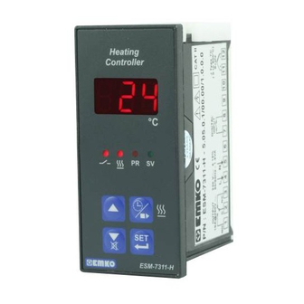
ESM-
Digital , ON / OFF Heating Controller
- 3 Digits display
- NTC Input or,
PTC Input or,
J type Thermocouple Input or,
K type Thermocouple Input or,
2-Wire PT 100 Input or,
2-Wire PT 1000 Input (It must be determined in order)
- ON/OFF temperature control
- Adjustable temperature offset
- Set value low limit and set value high limit boundaries
- Relay or SSR driver output
- Digital Input (Cooking time start/stop input)
- Adjustable cooking time from front panel
- Temperature control according to the cooking time (Timer)
- User can select to start cooking time (Timer) when temperature
reaches to the set value
- Temperature control with manual heating function
- Alarm parameters
- Adjustable internal buzzer according to cooking time , probe
defect and alarm status
- Button protection
- Password protection for programming section
7311-H
35 x 77
Instruction Manual. ENG ESM-
DIN Size
7311-H
02 V02 08/14
Advertisement
Table of Contents

Subscribe to Our Youtube Channel
Related Manuals for EMKO ESM-7311-H


Summary of Contents for EMKO ESM-7311-H
- Page 1 ESM- 7311-H 35 x 77 DIN Size Digital , ON / OFF Heating Controller - 3 Digits display - NTC Input or, PTC Input or, J type Thermocouple Input or, K type Thermocouple Input or, 2-Wire PT 100 Input or, 2-Wire PT 1000 Input (It must be determined in order) - ON/OFF temperature control - Adjustable temperature offset...
- Page 2 ABOUT INSTRUCTION MANUAL Instruction manual of ESM-7311-H Heating Controller consists of two main sections. Explanation of these sections are below. Also, there are other sections which include order information and technical specifications of the device. All titles and page numbers in instruction manual are in section.
-
Page 3: Table Of Contents
1.2 ORDERING INFORMATION 1.3 WARRANTY 1.4 MAINTENANCE 2.INSTALLATION............................ Page 2.1 GENERAL DESCRIPTION 2.2 FRONT VIEW AND DIMENSIONS OF ESM-7311-H TEMPERATURE CONTROLLER 2.3 PANEL CUT-OUT 2.4 ENVIRONMENTAL RATINGS 2.5 PANEL MOUNTING 2.6 INSTALLATION FIXING CLAMP 2.7 REMOVING FROM THE PANEL 3.ELECTRICAL WIRINGS........................ - Page 4 EU DECLARATION OF CONFORMITY Manufacturer’s Name : EMKO ELEKTRONIK A.S. Manufacturer’s Address : DOSAB, Karanfil Sk., No:6, 16369 Bursa, TURKEY The manufacturer hereby declares that the product: Product Name Heating Controller Type Number : ESM-7311H Product Category : Electrical equipment for measurement, control and...
-
Page 5: General Specifications
1.Preface ESM-7311-H series heating controllers are designed for measuring and controlling temperature. They can be used in many applications with their easy use, On/ Off control form and cooking time properties. Some application fields which they are used are below:... -
Page 6: Ordering Information
Customer 1.3 Warranty EMKO Elektronik warrants that the equipment delivered is free from defects in material and workmanship. This warranty is provided for a period of two years. The warranty period starts from the delivery date. This warranty is in force if duty and responsibilities which are determined in warranty document and instruction manual performs by the customer completely. -
Page 7: Installation
2.Installation Before beginning installation of this product, please read the instruction manual and warnings below carefully. In package , - One piece unit - Two pieces mounting clamps - One piece instruction manual A visual inspection of this product for possible damage occured during shipment is recommended before installation. -
Page 8: General Description
2.1 General Description Mounting Clamp Front Panel IP65 protection Panel surface NEMA 4X (maximum thickness 15 mm / 0.59 inch) 2.2 Front View and Dimensions of ESM-7311-H Heating Controller Maximum 15 mm / 0.59 inch Heating Controller °C ESM-7311-H 58.5 mm / 2.30 inch 35 mm / 1.38 inch... -
Page 9: Panel Cut-Out
2.3 Panel Cut-Out 29 mm / 1.14 inch 56 mm / 3.82 inch (min) -
Page 10: Environmental Ratings
2.4 Environmental Ratings Operating Conditions 0 to 50 °C Operating Temperature Rh (non-condensing) Max. Operating Humidity : Up to 2000 m. Altitude Forbidden Conditions: Corrosive atmosphere Explosive atmosphere Home applications (The unit is only for industrial applications) 2.5 Panel Mounting 1-Before mounting the device in your panel, make sure that the cut-out is of the right size. -
Page 11: Installation Fixing Clamp
2.6 Installation Fixing Clamp The unit is designed for panel mounting. 1-Insert the unit in the panel cut-out from the front side. 2- Insert the mounting clamps to the holes that located left and right sides of the device and make the unit completely immobile within the panel Montage of the unit to a system must be done with it’s own fixing clamps. -
Page 12: Electrical Wirings
3.Electrical Wiring You must ensure that the device is correctly configured for your application. Incorrect configuration could result in damage to the process being controlled, and/or personal injury. It is your responsibility, as the installer, to ensure that the configuration is correct. Device parameters has factory default values. -
Page 13: Electrical Wiring Diagram
3.2 Electrical Wiring Diagram Electrical wiring of the device must be the same as ‘Electrical Wiring Diagram’ below to prevent damage to the process being controlled and personnel injury. P/N : ESM- 7311-H CAT II OUTPUT DIGITAL PTC, PT-100 10 A@250 V V PT-1000 INPUT (+) (-) -
Page 14: View Of The Device Label
3.3 View of the Device Label Device Label for J Type ( 0 ; 800 ) scaled, Thermocouple input, 230V Supply Voltage Input and Relay Output CAT II P/N : ESM-7311-H - 5.05.0.1/00.00/1.0.0.0 OUTPUT DIGITAL J Type TC 230 V ±... -
Page 15: Supply Voltage Input Connection Of The Device
3.4 Supply Voltage Input Connection of the Device Connection of Supply Voltage Connection of Supply Voltage Input Input Note-1 Note-1 External External Fuse Fuse (1 A T) (1 A T) Power Power Supply Supply Switch Switch Supply Voltage Supply Voltage 230 V (±... -
Page 16: Temperature Input Sensor Connection
3.5 Temperature Sensor Input Connection 3.5.1 TC (Thermocouple) Connection Connect the wires with the polarity as shown in the figure left. A l w a y s u s e c o m p e n s a t i o n w i r e corresponding to the thermocouple used. - Page 17 3.6 Galvanic Isolation Test Values of ESM- 7311-H Temperature Controller 2000 ESM- 7311-H-5..500V ( For ESM-7311-H-3..) Supply Voltage Ground Input 2000V V 2000V V Output-1 Relay Output 2000V V Optional SSR Driver Output 2000V V Analog Inputs 2000 V V...
-
Page 18: Output Connections
3.7 Output Connections 3.7.1 Relay Output Connection Device 10 V T Fuse Load Fuses must be selected according to the application. 3.7.2 Output (SSR Driver Output) Connection Device Last Control Element (SSR) Max. 15mA Fuse Load Fuses must be selected according to the application. -
Page 19: Front Panel Definition And Accessing To The Menus
Note-1 Cooking Button It is used to Cooking Time (Timer) increase the value Value Access, and access to the parameter in ESM-7311-H Cooking ON/OFF programming Button. mode. Note-1 It is used to enter to the SET It is used to... -
Page 20: Changing And Saving Set Value
4.2 Changing and Saving Set Value Main Operation SET Value SET Value Main Operation Screen Screen Screen Screen °C °C °C °C When set button is SV led lights off Press set button Change the SET pressed, SV led and main value with for saving the SET lights on and SET... -
Page 21: Programming Mode Parameter List
4.4 Programming Mode Parameter List Hysteresis Parameter for Output ( Default = 1 ) From 1 to 100 °C for TC Type devices, From 1 to 100 °C for PT-100 (-50°C , 400°C) and PT-1000 (-50°C , 400°C) , From 0.1 to 10.0 °C for PT-100 (-19.9°C, 99.9°C) and PT-1000 (-19.9°C, 99.9°C) From 1 to 20 °C for PTC (-50°C, 150°C) and NTC (-50°C, 100°C), From 0.1 to 10.0 °C PTC (-19.9°C, 99.9°C) and NTC (-19.9°C, 99.9°C) Temperature... - Page 22 Cooking Time Starting Conditions Parameter ( Default = 0 ) This parameter can be observed if cooking time (Timer) is 1. ³ Cooking time (Timer) is started with cooking ON/OFF button or when cooking time start/stop input is getting closed condition. Cooking time (Timer) is started when temperature reaches to the process set value after pressing cooking ON/OFF button or when cooking time start/stop input is getting closed condition.
-
Page 23: Cooking Time (Timer) On/Off Operation
Buzzer is Active During This Time ( Default = This parameter can be observed if buzzer function selection is 1. ³ It can be adjusted from 1 to 99 minutes. When this parameter is 1, if decrement button is pressed, is observed. -
Page 24: Operation Graphics Of Esm-7311-H Heating Controller
4.6 Operation Graphics of ESM-7311-H Heating Controller 1- When cooking time parameter 1, if selection of temperature control and starting ³ the cooking time parameter = 0 ( Temperature control and cooking time starts at power on) is selected; ( Continuous Operation) - Page 25 3- When cooking time parameter 1, if selection of temperature control and starting ³ the cooking time parameter = 2 ( Temperature control and cooking time (Timer) can be started by pressing cooking ON/OFF button or when cooking time start/stop input is getting closed condition) is selected;...
- Page 26 4.7 Easy Access Diagram of Programming Mode Parameters Hysteresis Programming Mode Password Entering Password Entering Main Operation Parameter Entering Screen Screen Screen Screen 5 secs. °C °C °C °C °C Enter password with increment Press SET/OK button for and decrement buttons accessing parameters Temperature Control Cooking Time...
-
Page 27: Entering To The Programming Mode, Changing And Saving Parameters
4.8 Entering to the Programming Mode, Changing and Saving Parameters Main Operation Screen °C °C °C °C Programming Mode Password Password When SET button is Entering Screen Entering Screen Entering Screen pressed for 5 seconds, “PR” led starts to blink. Press increment Enter programming Press SET/OK... - Page 28 Minimum Set Minimum Set Minimum Set Minimum Set Value Parameter Value Value Value Parameter °C °C °C °C Programming Programming Screen Screen Press increment button Change the value Press set button for Press set button for for accessing to the with increment and saving the parameter.
-
Page 29: Failure Messages In Esm- 7311-Hheating Controller
5. Failure Message in ESM-7311-H Heating Controller 1- Probe failure in analog inputs. Sensor connection is wrong or there is no sensor connection. When this message is on the screen, if buzzer Heating Controller function selection parameter is 3 or 4 , internal buzzer starts to operate. -
Page 30: Specifications
6. Specifications : Heating Controler Device Type : 35 mm x 77 mm x 62.5 mm plastic housing for panel Housing&Mounting Mounting. Panel cut-out is 71 x 29 mm : Ip65 at front, IP20 at rear) Protection Class : Approximately 0.20 Kg. Weight : Standard, indoor at an altitude of less than 2000 meters Environmental Ratings...
Need help?
Do you have a question about the ESM-7311-H and is the answer not in the manual?
Questions and answers