Table of Contents
Advertisement
Quick Links
Advertisement
Table of Contents

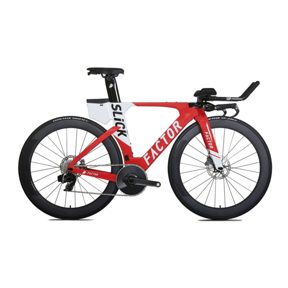
Summary of Contents for Factor SLiCK
- Page 1 FACTORBIKES.COM Assembly Manual V1.09...
- Page 2 Factor bicycle. This lifetime limited warranty is not transferable. the lifetime of the original owner of each new Factor bicycle or frameset that the bicycle frame or If the bicycle is purchased as a gift, the original recipient of the gift is considered to be the original frameset is free of defective materials and workmanship.
- Page 3 Miscellaneous: the bicycle in, severe conditions or climates. In the event that Factor prevails in any court action, you agree to reimburse Factor for the expenses, Labour and/or transport charges for full or part replacement, repair, return or changeover. including attorney’s fees and expenses of litigation incurred by Factor in defending against your claim.
- Page 4 Instructions Similar to a Formula 1 car your Factor Slick requires a bit of patience and mechanical skill to achieve a truly impressive result. We recommend that you have your bicycle assembled and maintained by an authorized Factor dealer. Make sure to let your...
- Page 5 Assembly Manual Adjust the set back and saddle angle to the desired Insert battery in the seatpost. position. Tighten the M6 saddle clamp bolt to 12Nm. Place the battery holders around the Di2 battery. The male shell grooves must match with the female battery groove. Before assembly, the wedge must be adjusted as pictured.
- Page 6 Connect the Di2 cable to the battery. Insert seatpost into the frame to the desired height. Note: Your Factor frame set requires a minimum of 90 mm of seatpost insertion. The minimum insertion is clearly marked on the seat post. Failure to achieve the minimum insertion could cause damage to the seat post or frame resulting in serious injury or death.
- Page 7 Assembly Manual Install stem and tighten M6x20L bolts to 10 Nm Lightly grease and install steerer rod and tighten until there Check headset adjustment as bearing preload may have is no bearing play but the headset still spins freely. changed during stem installation Secure headset adjustment by tightening M5x16L bolt to 6 Nm...
- Page 8 Assembly Manual Di2 cable routing overall view Park Tool offers an excellent internal cable routing kit (Park Tool IR-1) to help you easily route your cables. If you do not have access to this kit you can use a derailleur inner wire and a 5mm metal cable ferrule to route your wires.
- Page 9 Assembly Manual Route the rear derailleur Di2 cable through the Route the front derailleur Di2 cable through the seat chainstay. Install Di2 cable grommet. Connect to the tube hole to the bottom bracket exit window. Connect Di2 junction B. to the Di2 Junction B. Route the Di2 cable from the Junction A to the Junction B through the down tube (as pictured) to the bottom bracket shell exit window.
- Page 10 Assembly Manual Install armrest plates and secure by tightening M6x16L bolts to 6 Nm Select the desired armrest cup position and secure by tightening M5x12L bolts to 4 Nm Select desired base plate height and spacers. Attach extension tower to top plate tightening M6 bolts to 8 Nm. Use the table below to determine the correct bolt length.
- Page 11 Assembly Manual Route front and rear brake cable housings through base bar 4-10 4-11 Route front brake cable into stem cable stop while carefully maneuvering the handlebar assembly Route Di2 cables through base bar and install brake/shift onto the stem. levers Di2 shifter wires...
- Page 12 Assembly Manual 4-11 4-12 Route rear brake cable through down tube as pictured 4-13 4-14 4-15 Route Di2 cables through stem cover cable port and install into Junction A Secure handlebar to stem by tightening M6x25L bolts to 8 Nm Secure Junction A to stem cover using cable ties as pictured...
- Page 13 Assembly Manual 4-16 4-12 4-13 Install stem cover and secure by tightening M3x5L bolts to 0.5 Nm 4-15 Front Brake Installation Front Brake Installation Install brake wedge. Use grub screws to adjust each brake arm until the brake pad is 2-3mm from the rim. It is very important that the wedge is positioned between the rollers as pictured.
- Page 14 Assembly Manual Route brake inner wire through wedge and tighten 6-7 Nm Cut the brake inner wire short enough to prevent it from Install brake cover by tightening M4x10 bolts to 2 Nm taking care not to change the wedge position contacting the brake spring Bottom Bracket Apply Loctite 641 inside the bottom bracket shell...
- Page 15 Assembly Manual For 24 or 22 mm cranks install the included Wheels MFG BBright reducers/adapters. Bottle cage Install down tube cage bridge and tighten M5 torx head bolts Install cage and tighten M5 torx head bolts to 2 Nm to 2 Nm.
- Page 16 Assembly Manual Rear dropout In case of dropout replacement, apply Loctite 243 on bolts threads and tighten to 1 Nm. Storage Pack Slide the Storage Pack down the rail until it securely clicks Install the rear Storage Pack rail to the seat tube by tightening into position.
- Page 17 Assembly Manual Snap the stem cover onto the front Nutrition Pack. Covers are available for both 0 and 40 mm stem options. Install the front Nutrition Pack by tightening the provided M5 torx head bolts to 2 Nm. Install the Storage Pack cover making sure to carefully latch each tab into their corresponding holes.
- Page 18 FACTORBIKES.COM...


Need help?
Do you have a question about the SLiCK and is the answer not in the manual?
Questions and answers