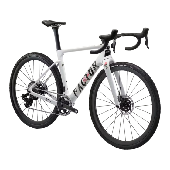
Summary of Contents for Factor Ostro Gravel
- Page 2 Ostro Gravel manual...
- Page 3 Subject to the following limitations, terms and conditions, Factor warrants to the original owner for the lifetime of the original owner of each new Factor bicycle or frameset that the bicycle If the bicycle is purchased as a gift, the original recipient of the gift is considered to be the frame or frameset is free of defective materials and workmanship.
- Page 4 In the event that Factor prevails in any court action, you agree to reimburse Factor for the expenses, including attorney’s fees and expenses of litigation incurred by Factor in defending Labour and/or transport charges for full or part replacement, repair, return or changeover.
-
Page 5: Necessary Tools
Instructions Similar to a Formula 1 car, your Factor OSTRO requires a bit of patience and mechanical skill to achieve a truly impressive result. We recommend that you have your bicycle assembled and maintained by an authorized Factor dealer. Make sure to let your mechanic know how much you appreciate their help building the bike of your dreams! - Page 6 Seatpost Seat Route Di2 wire through seat tube and out through bottom ● Attach seat to post, applying carbon compound to the lower saddle bracket hole, attach Junction B to the end of the Di2 wire at the clamp/carbon seat post head bottom bracket ●...
- Page 7 Connect the Di2 cable to the battery. Insert seat post into the frame to the desired height. Note: Your Factor frame set requires a minimum of 90 mm of seat post insertion. The minimum insertion is clearly marked on the seat post. Failure to achieve the minimum insertion could cause damage to the seat post or frame resulting in serious injury or death.
- Page 8 Di2 Cable Routing Note: Similar to a Formula 1 car your Factor OSTRO Gravel requires a bit of patience and mechanical skill to achieve a truly Di2 cable routing overall view impressive result. We recommend that you have your bicycle assembled and maintained by an authorized Factor dealer.
- Page 9 Connect to the Di2 Junction B Route the rear derailleur Di2 cable through Install Di2 cable grommet. the chainstay. Route the front derailleur Di2 cable through the seat tube hole to the bottom bracket exit port. Install Di2 cable grommet. Connect to the Di2 Junction B...
- Page 10 Cutting the steerer ● Assemble your preferred quantity of spacers, as well as the HS assembly, dry-fitting this arrangement onto the uncut steerer tube ● Hand tighten the assembly to remove any play. Mark the steerer tube at 3mm lower than the top of the stem area Carefully cut the steerer using a Park SG-6 or similar steerer cutting guide using a sharp fine tooth hacksaw blade.
-
Page 11: Hose Routing
Hose routing Install rear brake and fish hose through the frame and out the headset ● install the anti rattle rear brake hose foam sleeve ● ● Insure that the clear plastic anti wear guard portion of the anti rattle hose covering is adjacent to the head tube to shield the brake hose from the steerer rotation... - Page 12 Hose routing Attach front brake to fork and route hose through the molded opening ● Lightly grease lower bearing seat and install bearing over top of the hoses, repeat this process at the upper bearing and install the fork. ● ●...
- Page 13 Hose routing Route hoses through the bars at the opening, and pull the hoses out the brake lever locations. ● Lightly grease lower bearing seat and install bearing over top of the hoses, repeat this process at the upper bearing and install the fork. ●...
- Page 14 Bar mounting ● Install compression plug, applying assembly compound between the compression plug and the steerer tube. Tighten to 8Nm. ● Lightly grease the compression cap screw and install, tightening until the bearing preload increases to remove any play in the system. ●...
- Page 15 ● If you are using a front derailleur, install the mount as shown, tightening to 3Nm. ● If you aren’t using a Front Derailleur mount, look for the supplied blanking plate and attach with a single screw.
- Page 16 Computer mount cont. ● If you are using the double go pro mount, use the two supplied screws to install it. ● If you are using accessories, be sure to follow the manufacturer's instruction. Combined weight of the two ● combined weight of the two components should not exceed 300g...
- Page 17 Black Inc GoPro Computer Mount ● If you wish to add other accessories, the second rearward double GoPRO mount works to keep the weight of those accessories towards the center of the stem, reducing the moment arm about which the weight acts, minimizing the risk of breakage or shifting.


Need help?
Do you have a question about the Ostro Gravel and is the answer not in the manual?
Questions and answers