Burkert multiCELL 8619 Quick Start Manual
Modular transmitter/controller
Hide thumbs
Also See for multiCELL 8619:
- Operating instructions manual (194 pages) ,
- Quick start manual (51 pages) ,
- Operating instructions manual (168 pages)

Subscribe to Our Youtube Channel
Related Manuals for Burkert multiCELL 8619


Summary of Contents for Burkert multiCELL 8619
- Page 1 Type 8619 multiCELL Modular transmitter/controller Modularer Transmitter/Controller Transmetteur/contrôleur modulaire Quickstart...
- Page 2 We reserve the right to make technical changes without notice. Technische Änderungen vorbehalten. Sous réserve de modifications techniques. © 2010 - 2013 Bürkert SAS Operating Instructions 1303/3_EU-ML 00561095 Original_FR...
-
Page 3: Table Of Contents
Type 8619 Contents About the QuickstArt ................................3 1.1. symbols used ..................................3 1.2. Definition of the word "device" ............................3 intenDeD use ....................................4 bAsic sAfety informAtion ..............................4 GenerAl informAtion ................................5 4.1. manufacturer's address and international contacts ....................5 4.2. Warranty conditions ................................5 4.3. information on the internet ...............................5 Description .......................................6 5.1. Area of application ................................6 5.2. Description of the device name plate .........................6 technicAl DAtA ....................................7 6.1. conditions of use ...................................7 6.2. compliance to standards and directives ........................7 6.3. General technical data ................................7 instAllAtion AnD WirinG . - Page 4 Type 8619 8.7. process level ..................................29 8.8. configuration level access ............................30 8.9. calibrating the measuring sensors ...........................31 8.10. process inputs or values ..............................33 mAintenAnce AnD troubleshootinG ........................35 9.1. safety instructions ................................35 9.2. maintenance of the multicell .............................35 9.3. if you encounter problems ............................35 spAre pArts AnD Accessories ............................36 10. 11. pAckAGinG, trAnsport ................................36 storAGe ......................................36 12. DisposAl of the Device ................................36 13. english...
-
Page 5: About The Quickstart
Refer to the corresponding instruction manual to get a complete description of the device. The instruction manual for type 8619 can be found on the CD provided with the device or on internet under: www.burkert.com Type 8619 1.1. symbols used danger Warns against an imminent danger. -
Page 6: Intended Use
Type 8619 Intendeduse inTenDeD use use of this device that does not comply with the instructions could present risks to people, nearby installations and the environment. • The device is intended, depending on the modules fitted and the measurement sensors connected, for the acquisition, processing, transmission and regulation of physical parameters such as pH, conductivity, tem- perature or flow rate..•... -
Page 7: General Information
The addresses of our international sales offices are available on the internet at: www.burkert.com 4.2. Warranty conditions The condition governing the legal warranty is the conforming use of the multiCELL 8619 in observance of the operating conditions specified in this manual. 4.3. information on the internet You can find the Operating instructions and technical data sheets regarding the type 8619 at: www.burkert.com... -
Page 8: Description
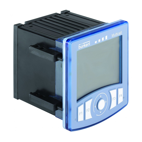
Type 8619 Description DescripTion 5.1. Area of application The 8619 multiCELL is a multifunction device intended to display, transmit and regulate various physical param- eters. It can be used, for example, to manage a water treatment system (a boiler, a cooling tower or a reverse osmosis system). -
Page 9: Technical Data
Type 8619 Technicaldata TechnicAl DATA 6.1. conditions of use Ambient temperature -10 to +70 °C (operating, without memory card), restricted to 0 ... +70°C if a memory card is used Air humidity < 85 %, non condensated Height above sea level max. - Page 10 Type 8619 Technicaldata Silicone PBT, contacts in gold-plated copper alloy Stainless steel 304 Stainless steel 316 (A4) Silicone Figure 2 : Materials used for the multiCELL max. 4 mm (wall thickness) Figure 3 : Dimensions of the multiCELL [mm] 6.3.2. specifications of the "m0:mAin"...
- Page 11 Type 8619 Technicaldata Max. power consumption (without additional 1.5VA module, outputs not connected) Power distribution ("PWR OUT") 12-36 V DC, 1.8A max. All digital inputs ("DI") • Switching threshold V : 5 à 36 V DC • Switching threshold V : <...
- Page 12 Type 8619 Technicaldata Analogue inputs ("AI") • Any connection mode, in sink or source mode • Galvanically insulated • Accuracy: ±0,25% • Current input: 0 - 22 mA or 3,5 - 22 mA. Max. voltage: 36 V DC. Impedance: 50 W. Resolution : 1.5 µA •...
- Page 13 Type 8619 Technicaldata 6.3.6. specifications of the "ph/redox" module ph measurement • pH measurement range • -2.00...+16.00 • 0.01pH • Resolution of pH measurement • Accuracy of pH measurement • 0.02pH • Potential difference measurement range • -600...+600mV • Resolution of potential difference •...
- Page 14 Type 8619 Technicaldata conductivity measurement (with connected conductivity sensor) • Measurement range • 0.000 µS/cm...2 S/cm (depends on the conductivity sensor) • 10 S/cm • Measurement resolution • Measurement error • < 0.5% of measured value + sensor error resistivity measurement (with connected conductivity sensor) • 0.500W.cm...100MW.cm (depends on the conductivity sensor) •...
-
Page 15: Installation And Wiring
Type 8619 Installationandwiring insTAllATion AnD WirinG 7.1. safety instructions danger risk of injury due to electrical discharge. • Shut down and isolate the electrical power source before carrying out work on the system. • Observe all applicable accident protection and safety regulations for electrical equipment. WarnIng risk of injury due to non-conforming installation. - Page 16 Type 8619 Installationandwiring Stage 2: Body Prepare the 4 locking systems: → Insert a screw into each device. Screw → Tighten the screw until the end of the shaft of the screw is flush with the device. Stage 3: → Slide the housing into the cut-out with the con- nectors to the back until it can go no further.
-
Page 17: Electrical Wiring
Type 8619 Installationandwiring Stage 6: → Fully tighten the screws using an appropriate screwdriver. → Repeat stages 4 to 6 to fit the other 3 locking systems. Figure 4 : Insertion of the 8619 into a housing or cabinet 7.3. electrical wiring danger risk of injury due to electrical discharge. - Page 18 Type 8619 Installationandwiring 1st digital output at 1st 4-20 mA input at external instrument external instrument 0 VDC 5-36 VDC 2nd digital output at external 2nd 4-20 mA input at instrument external instrument Load 1 12-36 VDC 0 VDC 12-36 VDC 0 VDC 12-36 VDC Power supply...
- Page 19 Type 8619 Installationandwiring 12-36 VDC Power supply SUPPLY PWR OUT DI1 AO2 FE FE = functional earth Figure 6 : Connection example for the 8619 with two flow sensors, type 8030 8041 8071 Pls- Pls+ 4...20 12-36 VDC Power supply SUPPLY PWR OUT DI1 AO2 FE FE = functional earth...
- Page 20 Type 8619 Installationandwiring 7.3.3. Wiring the input module "inpuT" The "INPUT" inputs module has: • Two analogue inputs; • Two digital inputs. The inputs are galvanically insulated, and therefore voltage free. 1st 0/4-20 mA output (at external instrument) 0 VDC 2nd 0/4-20 mA output (at external instrument) 5-36 VDC 12-36 VDC...
- Page 21 Type 8619 Installationandwiring 1st 0/4-20 mA output 2nd 0/4-20 mA output (at external instrument) (at external instrument) + - I 12-36 VDC 12-36 VDC 0 VDC 0 VDC 1st digital output (at external instrument) 0 VDC 12-36 VDC 2nd digital output (at external instrument) 0 VDC 6 7 8...
- Page 22 Type 8619 Installationandwiring 7.3.4. Wiring the output module "ouT" The "OUT" outputs module has two 4-20 mA analogue outputs and two digital outputs. The outputs are galvani- cally insulated, and therefore voltage free. 1st 4-20 mA 2nd 4-20 mA input (at input (at external external instrument) instrument)
- Page 23 Type 8619 Installationandwiring Equipotential electrode black Temperature Reference sensor electrode pH measurement electrode 6 7 8 FE = functional earth Colour of the wires in the Bürkert connection cables with order codes 561904, 561905 or 561906. Colour of the wires in the Pt1000 sensor with order code 427023 and its Bürkert connection cable with order code 427113.
- Page 24 Type 8619 Installationandwiring Temperature Oxidation reduction potential sensor measurement electrode Reference electrode Strap (not delivered) 6 7 8 FE = functional earth Figure 14 : Wiring an oxidation reduction potential sensor and a Pt100 or Pt1000 temperature sensor in a pH/ORP module Oxidation reduction potential measurement electrode...
- Page 25 Type 8619 Installationandwiring Temperature sensor 6 7 8 FE = functional earth Figure 17 : Wiring a resistive conductivity cell with 4 electrodes and a Pt100 or Pt1000 temperature sensor in a conduc- tivity module english...
-
Page 26: Adjustment And Commissioning
Type 8619 Adjustmentandcommissioning ADjusTmenT AnD commissioninG 8.1. safety instructions WarnIng risk of injury due to non-conforming adjustment. Non conforming adjustment could lead to injuries and damage the device and its environment. • The operators in charge of adjustment must have read and understood the contents of this manual. •... -
Page 27: Description Of The Icons
Type 8619 Adjustmentandcommissioning 8.3. Description of the icons M0:MAIN 2010/06/29 13:40 6.000 20.00 MENU Figure 19 : Position of the icons icon meaning and alternatives Default icon when process monitoring is not activated via the "Diagnostics" menu; if monitoring is activated, this icon indicates that the parameters monitored are not out of range. If at least one monitoring is activated, the alternative icons in this position are: •... -
Page 28: Using The Navigation Button And The Dynamic Keys
Type 8619 Adjustmentandcommissioning 8.4. using the navigation button and the dynamic keys The arrows displayed show the directions in which you can browse in this view. To activate the dynamic MENU ABORT SAVE OK To activate the dynamic function to the far left, function to the far right, press press F1 LED A: shows the system... -
Page 29: Entering Some Text
Type 8619 Adjustmentandcommissioning you want to... press..browse in Process level next view previous view next level previous level ...browse in the Configuration level menus display the next display the pre- menu vious menu ...browse in the menu functions highlight the next highlight the pre- function vious function... -
Page 30: Operating Levels
Type 8619 Adjustmentandcommissioning Cursor of the data entering area Selector Edit name a b c d e g 7 8 9 h i j k l m n 4 5 6 The arrows indicate that the selector o p q r s t u 1 2 3 can be moved on the line or that the v w x y z + - . -
Page 31: Process Level
Type 8619 Adjustmentandcommissioning 8.7. process level M6:Outputs 2010/06/29 13:40 M2:Conductivity 13:40 2010/06/29 mS/cm M1:pH 13:40 13:40 ..M0:MAIN: 2010/06/29 6.53 5.000 25.2 2010/06/29 13:40 M0:MAIN: 0.500 °C 12.00 39.20 30.00 MENU °C 25.2 1.000 6.000 33.00 20.00 MENU Views of the modules connected to the device (cannot be modified): •... -
Page 32: Configuration Level Access
Type 8619 Adjustmentandcommissioning 8.8. configuration level access Parameters This is when the On any view in Code device is be- ing parame- tered........ "Param- System Process level, incorrect This is Display when the eters" code device is be- Functions ing parame- press tered.... -
Page 33: Calibrating The Measuring Sensors
Type 8619 Adjustmentandcommissioning 8.9. calibrating the measuring sensors 8.9.1. calibrating a flow sensor → Enter the K factor in pulse/liter unique to the fitting used. Refer to the user manual of the fitting used. Calibration M0:Inputs DI1/2:Flow K factor ENTERING Mx:Inputs 8.9.2. - Page 34 Type 8619 Adjustmentandcommissioning 8.9.4. calibrating a redox sensor • Modify the default calibration limits before calibrating your sensor in the menu "Parameters" -> "Mx:pH/ ORP" -> "Calibration limits" -> "Offset ORP". • In order not to interrupt the process, activate the HOLD function in the menu "Calibration -> System -> Hold".
-
Page 35: Process Inputs Or Values
Type 8619 Adjustmentandcommissioning 8.10. process inputs or values 8.10.1. on the m0:mAin board "Warning" = event generated by the multiCELL M0:MAIN None Warning "AOx" = analogue output "DOx" = digital output "System switch" = when the corresponding event is configured and activated SysSwitch "DIx"... - Page 36 Type 8619 Adjustmentandcommissioning 8.10.4. on the ph/redox module "pH" = measured pH of the fluid Mx:pH/ORP "mV" = measured pH of the fluid in mV "ORP" = measured oxidation reduction potential of the fluid in mV °C °F "°C" = measured temperature of the fluid in °C "°F"...
-
Page 37: Maintenance And Troubleshooting
Type 8619 Maintenanceandtroubleshooting mAinTenAnce AnD TroubleshooTinG 9.1. safety instructions danger risk of injury due to electrical discharge. • Shut down and isolate the electrical power source before carrying out work on the system. • Observe all applicable accident protection and safety regulations for electrical equipment. WarnIng risk of injury due to non-conforming maintenance. -
Page 38: Spare Parts And Accessories
Type 8619 Sparepartsandaccessories spAre pArTs AnD Accessories CaUTIOn risk of injury and/or material damage caused by the use of unsuitable parts. Incorrect accessories and unsuitable replacement parts may cause injuries and damage the device and the sur- rounding area. • Use only original accessories and original replacement parts from Bürkert. pAckAGinG, TrAnsporT aTTenTIOn Damage due to transport Transport may damage an insufficiently protected device. - Page 40 www.burkert.com...
Need help?
Do you have a question about the multiCELL 8619 and is the answer not in the manual?
Questions and answers