Bürkert 8619 multiCELL WM DC Manuals
Manuals and User Guides for Bürkert 8619 multiCELL WM DC. We have 4 Bürkert 8619 multiCELL WM DC manuals available for free PDF download: Operating Instructions Manual, Quick Start Manual
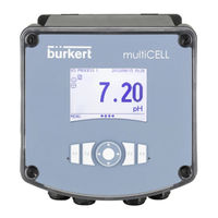
Bürkert 8619 multiCELL WM DC Operating Instructions Manual (194 pages)
Modular transmitter
Brand: Bürkert
|
Category: Controller
|
Size: 3 MB
Table of Contents
Advertisement
Burkert 8619 multiCELL WM DC Operating Instructions Manual (168 pages)
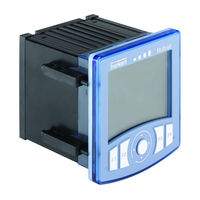
8619 series Modular transmitter / controller
Brand: Burkert
|
Category: Controller
|
Size: 2 MB
Table of Contents
Burkert 8619 multiCELL WM DC Quick Start Manual (52 pages)
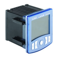
Modular transmitter/controller
Brand: Burkert
|
Category: Controller
|
Size: 1 MB
Table of Contents
Advertisement

Burkert 8619 multiCELL WM DC Quick Start Manual (51 pages)
Modular transmitter/controller
Brand: Burkert
|
Category: Transmitter
|
Size: 1 MB