
Related Manuals for Advantech EKI-2741FI


Summary of Contents for Advantech EKI-2741FI
- Page 1 User Manual EKI-2741FI/LXI/SXI 10/100/1000T (X) to Fiber Optic Gigabit Industrial Media Converters...
- Page 2 No part of this manual may be reproduced, copied, translated or transmitted in any form or by any means without the prior written permission of Advantech Co., Ltd. Information provided in this manual is intended to be accurate and reliable. How- ever, Advantech Co., Ltd.
-
Page 3: Declaration Of Conformity
This product has passed the CE test for environmental specifications when shielded cables are used for external wiring. We recommend the use of shielded cables. This kind of cable is available from Advantech. Please contact your local supplier for ordering information. -
Page 4: Packing List
Before setting up the system, check that the items listed below are included and in good condition. If any item does not accord with the table, please contact your dealer immediately. 1 x EKI-2741FI/LXI/SXI Industrial Ethernet Switch 2 x Wall Mounting Bracket and Screws ... -
Page 5: Safety Instructions
(140° F). THIS COULD DAMAGE THE EQUIPMENT. THE EQUIPMENT SHOULD BE IN A CONTROLLED ENVIRONMENT. CAUTION: DANGER OF EXPLOSION IF BATTERY IS INCORRECTLY REPLACED. REPLACE ONLY WITH THE SAME OR EQUIVALENT TYPE RECOMMENDED BY THE MANUFACTURER, DISCARD USED BATTERIES ACCORDING TO THE MANUFACTURER'S INSTRUCTIONS. EKI-2741FI/LXI/SXI User Manual... - Page 6 Technical Support and Assistance Visit the Advantech web site at www.advantech.com/support where you can find the latest information about the product. Contact your distributor, sales representative, or Advantech's customer service center for technical support if you need additional assistance.
-
Page 7: About This Manual
This user manual is intended to guide professional installers in installing and config- uring the Serial Device Server. It includes technical specifications, software utility introduction, as well as procedures for the use of the software utility to self-manage the devices. EKI-2741FI/LXI/SXI User Manual... -
Page 8: Table Of Contents
Connecting Hardware ................11 2.2.1 Choosing a Location ..............11 2.2.2 DIP Switch .................. 15 2.2.3 SFP Connection................15 2.2.4 Ethernet Connection ..............18 2.2.5 Fiber Connection................. 18 2.2.6 Power Connection............... 20 Chapter Troubleshooting ........21 Troubleshooting ..................22 EKI-2741FI/LXI/SXI User Manual viii... - Page 9 Removing a Fiber Optic Cable to a Transceiver............17 Figure 2.16 Removing an SFP Transceiver..................17 Figure 2.17 Ethernet Plug & Connector Pin Position..............18 Figure 2.18 Pin Assignment of the SC Connector ................19 Figure 2.19 Power Wiring for EKI-2741FI/LXI/SXI................20 EKI-2741FI/LXI/SXI User Manual...
-
Page 10: Chapter 1 Overview
Chapter Overview... -
Page 11: Introduction
EKI-2741FI/LXI/SXI also have the LFP (Link Fault Pass-through) feature, which allows the transmission of packets even when one link fails. EKI-2741FI/LXI/SXI forces the shutdown of the failed link to allow for an application continuous transmission. -
Page 12: Device Specifications
Rx Sensitivity: -18 dBm Parameters: 50/125 um, 62.5/125 um Single-mode Wavelength: 1310 nm (EKI-2741LX/LXI) Tx Power: -3/-9.5 dBm Rx Sensitivity: -20 dBm Parameters: 9/125 um Power Power 3.5W Consumption Power Input 12 ~ 48 V EKI-2741FI/LXI/SXI User Manual... - Page 13 FCC Part 15 Subpart B Class A, EN 55022 Class A EN 61000-4-2 EN 61000-4-3 EN 61000-4-4 EN 61000-4-5 EN 61000-4-6 EN 61000-4-8 Shock IEC 60068-2-27 Freefall IEC 60068-2-32 Vibration IEC 60068-2-6 EKI-2741FI/LXI/SXI User Manual...
-
Page 14: Chapter 2 Getting Started
Chapter Getting Started... -
Page 15: Hardware Overview
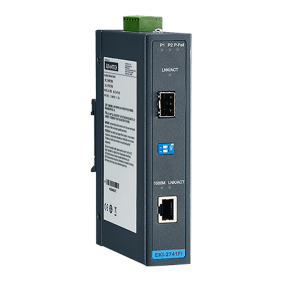
Hardware Overview 2.1.1 Front View The following view applies to EKI-2741FI. P1 P2 P-Fail LNK /ACT 1000M LNK /ACT EKI-2741FI Figure 2.1 Front View No. Item Description System LED panel See “LED Indicators” on page 9 for further details. LNK/ACT LED Link activity LED. -
Page 16: Figure 2.2 Front View
Link activity LED. Fiber port 1000 Mbps fiber port with SC type connector. DIP switch Confige operation mode for LFP (Link Fault Pass-through). 1000M, LNK/ACT 1000M LED and link activity LED. ETH port 10/100/1000Base-T/TX ports x 1. EKI-2741FI/LXI/SXI User Manual... -
Page 17: Rear View
Top View DC12 - 48V PWR2 1A@24V PWR1 V2- V2+ V1- V1+ P- Fail Figure 2.4 Top View No. Item Description Terminal block Connect cabling for power and alarm wiring Ground terminal Screw terminal used to ground chassis EKI-2741FI/LXI/SXI User Manual... -
Page 18: Led Indicators
Not connected to network. LINK/ACT (RJ45) Green on Connected to network. Blinking Network is active. Not connected to network. 2.1.5 Dimensions The following view applies to EKI-2741FI. 47.45 [1.87] 18 [0.71] 104 [4.09] 104 [4.09] 95 [3.74] 30 [1.18] 30 [1.18] Figure 2.5 Dimensions... -
Page 19: Figure 2.6 Dimensions
The following view applies to EKI-2741LXI and EKI-2741SXI. 47.45 [1.87] 18 [0.71] 104 [4.09] 104 [4.09] 95 [3.74] 30 [1.18] 30 [1.18] Figure 2.6 Dimensions EKI-2741FI/LXI/SXI User Manual... -
Page 20: Connecting Hardware
Installing the DIN-Rail Mounting Kit Insert the top back of the mounting bracket over the DIN rail. Push the bottom of the device towards the DIN rail until it snaps into place. DIN Rail Figure 2.7 Installing the DIN-Rail Mounting Kit EKI-2741FI/LXI/SXI User Manual... -
Page 21: Figure 2.8 Removing The Din-Rail
Rotate the bottom of the device towards you and away from the DIN rail. Once the bottom is clear of the DIN rail, lift the device straight up to unhook it from the DIN rail. DIN Rail Figure 2.8 Removing the DIN-Rail EKI-2741FI/LXI/SXI User Manual... -
Page 22: Figure 2.9 Installing Wall Mount Plates
Use the wall mount plates as a guide to mark the locations of the screw holes. Drill four holes over the four marked locations on the wall, keeping in mind that the holes must accommodate wall sinks in addition to the screws. Insert the wall sinks into the walls. EKI-2741FI/LXI/SXI User Manual... -
Page 23: Figure 2.10 Wall Mounting Screw Dimensions
Install the wall mount plate on the screws and slide it forward to lock in place, see the following figure. Figure 2.11 Wall Mount Installation Once the device is installed on the wall, tighten the screws to secure the device. EKI-2741FI/LXI/SXI User Manual... -
Page 24: Dip Switch
2.2.3 SFP Connection EKI-2741FI has one SFP slot for connecting to the network segment with single or multi-mode fiber. You can choose appropriate mini-GBIC module to plug into the slot. Make sure the module is aligned correctly and then slide the module into the SFP slot until a click is heard. -
Page 25: Figure 2.13 Installing An Sfp Transceiver
Insert the fiber cable into the transceiver. The connector snaps into place and locks. Figure 2.14 Attaching a Fiber Optic Cable to a Transceiver Repeat the previous procedures to install any additional SFP transceivers in the device. The fiber port is now setup. EKI-2741FI/LXI/SXI User Manual... -
Page 26: Figure 2.15 Removing A Fiber Optic Cable To A Transceiver
Hold the handle on the transceiver and pull the transceiver out of the slot. Handle Figure 2.16 Removing an SFP Transceiver Note! Replace the dust plug on the slot if you are not installing a transceiver. The dust plug protects hardware from dust contamination. EKI-2741FI/LXI/SXI User Manual... -
Page 27: Ethernet Connection
For half-duplex operation, the recommended maximum distance is 412 meters (1,352 ft.). Fiber segment using multi-mode connector type must use 50 or 62.5/125μm multimode fiber cable. You can connect two devices up to a 550 meters (1,804.46 ft.) distance. EKI-2741FI/LXI/SXI User Manual... -
Page 28: Figure 2.18 Pin Assignment Of The Sc Connector
MDI-X or uplink MDI port. Both EKI-2741LXI and EKI-2741SXI supports auto-crossover to make networking more easy and flexible. You can connect any RJ-45 (MDI-X) station port on the switch to any device such as a switch, bridge or router. EKI-2741FI/LXI/SXI User Manual... -
Page 29: Power Connection
Caution! Disconnect the power cord before installation or cable wiring. The EKI-2741FI/LXI/SXI supports dual 12 to 48 VDC power inputs and power-fail relay output. The following figure illustrates a P-Fail alarm application example. The P-Fail alarm contacts are visible on the front view of the terminal block. - Page 30 Chapter Troubleshooting...
-
Page 31: Chapter 3 Troubleshooting
If user still cannot resolve the problem, contact the local dealer for assistance. If the Industrial switch LED indicators are normal and the connected cables are correct but the packets still cannot transmit, please check your system’s Ether- net devices configuration or status. EKI-2741FI/LXI/SXI User Manual... - Page 32 No part of this publication may be reproduced in any form or by any means, electronic, photocopying, recording or otherwise, without prior written permis- sion of the publisher. All brand and product names are trademarks or registered trademarks of their respective companies. © 2017 Advantech Co., Ltd.
Need help?
Do you have a question about the EKI-2741FI and is the answer not in the manual?
Questions and answers