Table of Contents
Advertisement
Quick Links
Advertisement
Table of Contents
Troubleshooting

Subscribe to Our Youtube Channel
Related Manuals for Advantech EKI-2741SX


Summary of Contents for Advantech EKI-2741SX
- Page 1 EKI-2741F 10/100/1000Base-T to SFP (mini-GBIC) Type Fiber Optic Media Converter EKI-2741SX 10/100/1000Base-T to 1000Base-SX SC Type Fiber Optic Media Converter EKI-2741LX 10/100/1000Base-T to 1000Base-LX SC Type Fiber Optic Media Converter User Manual...
- Page 2 The documentation and the software included with this product are copyrighted 2007 by Advantech Co., Ltd. All rights are reserved. Advantech Co., Ltd. reserves the right to make improvements in the products described in this manual at any time without notice. No part of this manual may be reproduced, copied, translated or transmitted in any form or by any means without the prior written permission of Advantech Co., Ltd.
- Page 3 Because of Advantech′s high quality-control standards and rigorous testing, most of our customers never need to use our repair service. If an Advantech product is defective, it will be repaired or replaced at no charge during the warranty period. For out-of-warranty repairs, you will be billed according to the cost of replacement materials, service time and freight.
- Page 4 Step 2. Contact your distributor, sales representative, or Advantech’s customer service center for technical support if you need additional assistance. Please have the following information ready before you call: - Product name and serial number...
- Page 5 Safety Instructions 1. Read these safety instructions carefully. 2. Keep this User's Manual for later reference. 3. Disconnect this equipment from any AC outlet before cleaning. Use a damp cloth. Do not use liquid or spray detergents for cleaning. 4. For plug-in equipment, the power outlet socket must be located near the equipment and must be easily accessible.
- Page 6 Safety Precaution - Static Electricity Follow these simple precautions to protect yourself from harm and the products from damage. 1. To avoid electrical shock, always disconnect the power from your PC chassis before you work on it. Don't touch any components on the CPU card or other cards while the PC is 2.
-
Page 7: Table Of Contents
Contents Chapter 1 Overview........... 2 1.1 Introduction ............2 1.1.1 Fast Fiber Converters Module ....2 1.1.2 Dual Power Input ........2 1.1.3 Flexible Mounting ........2 1.1.4 Advanced Protection ......... 2 1.1.5 Wide Operating Temperature ....2 1.1.6 Easy Troubleshooting........ 2 1.2 Features.............. - Page 8 EKI-2741F-SX-LX User Manual viii...
-
Page 9: Chapter 1 Overview
Overview Sections include: Introduction Features Specifications Packing List Safety Precaution Chapter1... -
Page 10: Introduction
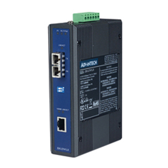
Chapter 1 Overview 1.1 Introduction The EKI-2741 is designed to convert Gigabit Ethernet networks to Gigabit fiber networks by transparently converting Ethernet signals to optic signals. The advantages of fiber optics are wide bandwidth, EMI immunity and long-distance transmission capability. Therefore, EKI-2741 is an ideal solution for “fiber to building” applications at central offices or local sites. -
Page 11: Features
1.2 Features • Provides 1 x SFP (mini-GBIC) type connector (EKI-2741F) • Provides 1 x 1000Base-SX or 1000Base-LX SC type connector (EKI-2741SX/LX) • Provides 1 x 10/100/1000Mbps Ethernet ports with RJ-45 connector • Supports full/half duplex flow control • Supports MDI/MDI-X auto-crossover •... -
Page 12: Specification
Up to 1000 Mbps Transmission Speed Interface Connectors Fiber : 1 x SFP(mini-GBIC) fiber connector (EKI-2741F) 1 x SC type fiber connector (EKI-2741SX/LX) 1 x RJ-45 6-pin removable screw terminal (power & relay) LED Indicators TX port: 10/100/1000M, Link/Active Fiber port: LNK/ACT... - Page 13 Environment Operating Temperature -10 ~ 60 ℃ (14~140℉) Wide temp. model: -40 ~ 75 ℃ (-40 ~ 167℉) Storage Temperature -40 ~ 85 ℃(-40 ~ 185℉) Operating Humidity 5 ~ 95% (non-condensing) Storage Humidity 0 ~ 95% (non-condensing) Certifications Safety UL, 60950-1, CAN/CSA-C22.2 No.60950 U.S.A.: FCC Part 15 CISPR 22 EU: EN55011, EN61000-6-4...
-
Page 14: Packing List
1.4 Packing List • 1 x EKI-2741F or EKI-2741SX or EKI-2741LX Industrial Ethernet Switch • 1 x eAutomation Industrial Communication CD-ROM with software, and User manual • 2 x Wall Mounting Bracket and Screws • 1 x DIN-rail Mounting Bracket and Screws •... -
Page 15: Chapter 2 Installation
Installation Sections include: LED Indicators Dimensions Mounting Network Connection Power Connection Chapter2... - Page 16 Chapter 2 Installation In this chapter, you will be given an overview of the EKI-2741F/SX/LX hardware installation procedures. 2.1 LED Indicators There are few LEDs display the power status and network status located on the front panel of EKI-2741F/SX/LX, each of them has its own specific meaning as the table below.
-
Page 17: Dip-Switch
2.2 DIP-Switch The DIP-Switch is used to configure operation mode for LFP (Link Fault Pass- Through) and operation mode for UTP/Fiber port. The default value of DIP-switch is OFF. Table 2.2: EKI-2741series DIP-Switch Definition S/W No Status Description Enables Port/Power Alarm Disable Port/Power Alarm Enables LFP Disables LFP... -
Page 18: Dimensions (Units: Mm)
2.3 Dimensions (units: mm) Figure 2.1: Front View of EKI-2741 series EKI-2741F-SX-LX User Manual... - Page 19 Figure 2.2: Side View of EKI-2741 series Chapter2...
- Page 20 Figure 2.3: Rear View of EKI-2741 series EKI-2741F-SX-LX User Manual...
- Page 21 The terminal block of power & relay is located on the top side. Please refer to page 16 for pin assignment. Figure 2.4: Top View of EKI-2741 series Chapter2...
-
Page 22: Mounting
2.4 Mounting The EKI-2741F/SX/LX support two mounting methods: DIN-rail & Wall. 2.4.1 Wall mounting EKI-2741F/SX/LX can be wall-mounted by using the included mounting kit. Then, hang on the EKI-2741F/SX/LX to the nails on the wall. First, use the screws included in the package to combine the EKI-2741F/SX/LX and metal mounting kit. -
Page 23: Din-Rail Mounting
2.4.2 DIN-rail Mounting You can also mount EKI-2741F/SX/LX on a standard DIN-rail by below steps. The DIN-rail kit is screwed on the industrial switch when out of factory. If the DIN-rail kit is not screwed on the industrial switch, please screw the DIN-rail kit on the switch first. First, hang the EKI-2741F/SX/LX to the DIN-rail with angle of inclination. - Page 24 Then, let the device down straight to slide over the rail smoothly. See Figure 2.7 Figure 2.7: Installation to DIN-rail Step 2 EKI-2741F-SX-LX User Manual...
-
Page 25: Network Connection
2.5 Network Connection • Twisted-pair segment can use unshielded twisted pair (UTP) or shielded twisted pair (STP) cabling. The cable between the link partner (switch, hub, workstation, etc.) and the converter, must be less than 100 meters (328 ft.) long and comply with the IEEE 802.3ab 1000Base-T standard for Category 5e or above. - Page 26 Second, insert the fiber cable of LC connector into the transceiver. Figure 2.10: LC connector to the transceiver To remove the LC connector from the transceiver, please follow the steps shown below: First, press the upper side of the LC connector from the transceiver and pull it out to release. Figure 2.11: Remove LC connector EKI-2741F-SX-LX User Manual...
- Page 27 Second, push down the metal loop and pull the transceiver out by the plastic part. Figure 2.12: Pull out from the SFP module Chapter2...
-
Page 28: Power Connection
2.6 Power Connection The EKI-2741F/SX/LX support dual +12 ~ 48 V power inputs and power-fail relay output. Figure 2.13: Pin Assignment of the Power Connector You can connect an alarm indicator, buzzer or other signaling equipment through the relay output. The relay opens if power input 1 or 2 fails ( “Open” means if you connect relay output with an LED, the light would be off). -
Page 29: Chapter 3 Troubleshooting
Troubleshooting Chapter2... - Page 30 Chapter 3 Troubleshooting Power Input Verify that is using the right power cord/adapter (+12~48 V ), please don’t use the power adaptor with DC output voltage higher than 48V, or it will burn this converter down. Cable Select the proper UTP/Fiber cable to construct your network. The single-mode converter must use single-mode fiber cable.
-
Page 31: Appendix A Pin Assignment & Wiring
Pin Assignment & Wiring Chapter2... - Page 32 Appendix A Pin Assignment & Wiring It is suggested to adopt ELA/TIA as the wiring of the RJ-45. Figure A.1: RJ-45 Pin Assignment Figure A.2: EIA/TIA-568B Figure A.2: EIA/TIA-568A EKI-2741F-SX-LX User Manual...
Need help?
Do you have a question about the EKI-2741SX and is the answer not in the manual?
Questions and answers