Table of Contents
Advertisement
Quick Links
Advertisement
Table of Contents
Troubleshooting

Related Manuals for Advantech EKI-2741F


Summary of Contents for Advantech EKI-2741F
-
Page 1: User Manual
EKI-2741F 10/100/1000Base-T to SFP (mini-GBIC) Type Fiber Optic Media Converter EKI-2741SX 10/100/1000Base-T to 1000Base-SX SC Type Fiber Optic Media Converter EKI-2741LX 10/100/1000Base-T to 1000Base-LX SC Type Fiber Optic Media Converter User Manual... - Page 2 The documentation and the software included with this product are copyrighted 2007 by Advantech Co., Ltd. All rights are reserved. Advantech Co., Ltd. reserves the right to make improvements in the products described in this manual at any time without notice. No part of this manual may be reproduced, copied, translated or transmitted in any form or by any means without the prior written permission of Advantech Co., Ltd.
- Page 3 Because of Advantech′s high quality-control standards and rigorous testing, most of our customers never need to use our repair service. If an Advantech product is defective, it will be repaired or replaced at no charge during the warranty period. For out-of-warranty repairs, you will be billed according to the cost of replacement materials, service time and freight.
-
Page 4: Declaration Of Conformity
Step 2. Contact your distributor, sales representative, or Advantech’s customer service center for technical support if you need additional assistance. Please have the following information ready before you call: - Product name and serial number... -
Page 5: Safety Instructions
Safety Instructions 1. Read these safety instructions carefully. 2. Keep this User's Manual for later reference. 3. Disconnect this equipment from any AC outlet before cleaning. Use a damp cloth. Do not use liquid or spray detergents for cleaning. 4. For plug-in equipment, the power outlet socket must be located near the equipment and must be easily accessible. - Page 6 Don't touch any components on the CPU card or other cards while the PC is 2. Disconnect power before making any configuration changes. The sudden rush of power as you connect a jumper or install a card may damage sensitive electronic components. EKI-2741F-SX-LX User Manual...
-
Page 7: Table Of Contents
1.5 Safety Precaution ..........6 Chapter 2 Installation........8 2.1 LED Indicators ............ 8 Table 2.1: EKI-2741F/SX/LX LED Definition.....8 2.2 DIP-Switch ............9 Table 2.2: EKI-2741series DIP-Switch Definition..9 2.3 Dimensions (units: mm) ........10 Figure 2.1: Front View of EKI-2741 series....10 Figure 2.2: Side View of EKI-2741 series ....11... - Page 8 EKI-2741F-SX-LX User Manual viii...
-
Page 9: Chapter 1 Overview
Overview Sections include: Introduction Features Specifications Packing List Safety Precaution Chapter1... -
Page 10: Introduction
1.1.2 Dual Power Input To reduce the risk of power failure, the EKI-2741F/SX/LX provide +12 ~ 48 V dual power inputs. If there is power failure, EKI-2741F/SX/LX will automatically switch to the secondary power input. -
Page 11: Features
1.2 Features • Provides 1 x SFP (mini-GBIC) type connector (EKI-2741F) • Provides 1 x 1000Base-SX or 1000Base-LX SC type connector (EKI-2741SX/LX) • Provides 1 x 10/100/1000Mbps Ethernet ports with RJ-45 connector • Supports full/half duplex flow control • Supports MDI/MDI-X auto-crossover •... -
Page 12: Specification
802.3z 10/100/1000Base-TX, 1000Base-SX, 1000Base-LX Transmission Distance Multi-Mode Fiber: 550m (EKI-2741SX) Single-Mode Fiber: 10km (EKI-2741LX) or SFP (mini-GBIC) Fiber: Up to 110km (EKI-2741F) Ethernet: Up to 100 meters (STP or UTP) Up to 1000 Mbps Transmission Speed Interface Connectors Fiber : 1 x SFP(mini-GBIC) fiber connector... - Page 13 Environment Operating Temperature -10 ~ 60 ℃ (14~140℉) Wide temp. model: -40 ~ 75 ℃ (-40 ~ 167℉) Storage Temperature -40 ~ 85 ℃(-40 ~ 185℉) Operating Humidity 5 ~ 95% (non-condensing) Storage Humidity 0 ~ 95% (non-condensing) Certifications Safety UL, 60950-1, CAN/CSA-C22.2 No.60950 U.S.A.: FCC Part 15 CISPR 22 EU: EN55011, EN61000-6-4...
-
Page 14: Packing List
1.4 Packing List • 1 x EKI-2741F or EKI-2741SX or EKI-2741LX Industrial Ethernet Switch • 1 x eAutomation Industrial Communication CD-ROM with software, and User manual • 2 x Wall Mounting Bracket and Screws • 1 x DIN-rail Mounting Bracket and Screws •... -
Page 15: Chapter 2 Installation
Installation Sections include: LED Indicators Dimensions Mounting Network Connection Power Connection Chapter2... -
Page 16: Table 2.1: Eki-2741F/Sx/Lx Led Definition
2.1 LED Indicators There are few LEDs display the power status and network status located on the front panel of EKI-2741F/SX/LX, each of them has its own specific meaning as the table below. Table 2.1: EKI-2741F/SX/LX LED Definition... -
Page 17: Dip-Switch
2.2 DIP-Switch The DIP-Switch is used to configure operation mode for LFP (Link Fault Pass- Through) and operation mode for UTP/Fiber port. The default value of DIP-switch is OFF. Table 2.2: EKI-2741series DIP-Switch Definition S/W No Status Description Enables Port/Power Alarm Disable Port/Power Alarm Enables LFP Disables LFP... -
Page 18: Dimensions (Units: Mm)
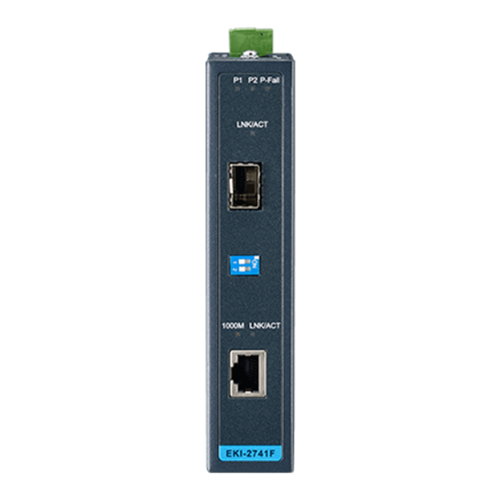
2.3 Dimensions (units: mm) Figure 2.1: Front View of EKI-2741 series EKI-2741F-SX-LX User Manual... -
Page 19: Figure 2.2: Side View Of Eki-2741 Series
Figure 2.2: Side View of EKI-2741 series Chapter2... -
Page 20: Figure 2.3: Rear View Of Eki-2741 Series
Figure 2.3: Rear View of EKI-2741 series EKI-2741F-SX-LX User Manual... -
Page 21: Figure 2.4: Top View Of Eki-2741 Series
The terminal block of power & relay is located on the top side. Please refer to page 16 for pin assignment. Figure 2.4: Top View of EKI-2741 series Chapter2... -
Page 22: Mounting
EKI-2741F/SX/LX can be wall-mounted by using the included mounting kit. Then, hang on the EKI-2741F/SX/LX to the nails on the wall. First, use the screws included in the package to combine the EKI-2741F/SX/LX and metal mounting kit. And then you can install the device firmly via the components, please see Figure 2.5 as below. -
Page 23: Din-Rail Mounting
The DIN-rail kit is screwed on the industrial switch when out of factory. If the DIN-rail kit is not screwed on the industrial switch, please screw the DIN-rail kit on the switch first. First, hang the EKI-2741F/SX/LX to the DIN-rail with angle of inclination. See figure 2.6. Figure 2.6: Installation to DIN-rail Step 1... -
Page 24: Figure 2.7: Installation To Din-Rail Step 2
Then, let the device down straight to slide over the rail smoothly. See Figure 2.7 Figure 2.7: Installation to DIN-rail Step 2 EKI-2741F-SX-LX User Manual... -
Page 25: Network Connection
2.5 Network Connection • Twisted-pair segment can use unshielded twisted pair (UTP) or shielded twisted pair (STP) cabling. The cable between the link partner (switch, hub, workstation, etc.) and the converter, must be less than 100 meters (328 ft.) long and comply with the IEEE 802.3ab 1000Base-T standard for Category 5e or above. -
Page 26: Figure 2.10: Lc Connector To The Transceiver
To remove the LC connector from the transceiver, please follow the steps shown below: First, press the upper side of the LC connector from the transceiver and pull it out to release. Figure 2.11: Remove LC connector EKI-2741F-SX-LX User Manual... -
Page 27: Figure 2.12: Pull Out From The Sfp Module
Second, push down the metal loop and pull the transceiver out by the plastic part. Figure 2.12: Pull out from the SFP module Chapter2... -
Page 28: Power Connection
2.6 Power Connection The EKI-2741F/SX/LX support dual +12 ~ 48 V power inputs and power-fail relay output. Figure 2.13: Pin Assignment of the Power Connector You can connect an alarm indicator, buzzer or other signaling equipment through the relay output. The relay opens if power input 1 or 2 fails ( “Open” means if you connect relay output with an LED, the light would be off). -
Page 29: Chapter 3 Troubleshooting
Troubleshooting Chapter2... - Page 30 If user still cannot resolve the problem, contact the local dealer for assistance. If the Industrial switch LED indicators are normal and the connected cables are correct but the packets still cannot transmit, please check your system’s Ethernet devices configuration or status. EKI-2741F-SX-LX User Manual...
-
Page 31: Appendix A Pin Assignment & Wiring
Pin Assignment & Wiring Chapter2... -
Page 32: Figure A.1: Rj-45 Pin Assignment
Appendix A Pin Assignment & Wiring It is suggested to adopt ELA/TIA as the wiring of the RJ-45. Figure A.1: RJ-45 Pin Assignment Figure A.2: EIA/TIA-568B Figure A.2: EIA/TIA-568A EKI-2741F-SX-LX User Manual...
Need help?
Do you have a question about the EKI-2741F and is the answer not in the manual?
Questions and answers