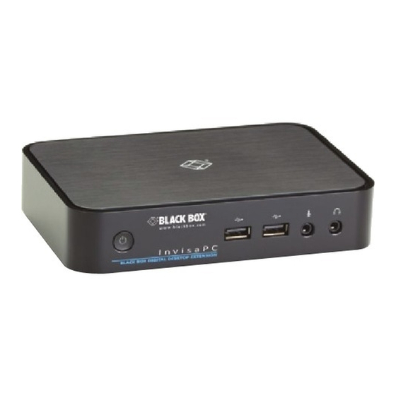
Black Box INVISAPC DTX1000-T Quick Start Manual
Invisapc dtx1000/2 series
Hide thumbs
Also See for INVISAPC DTX1000-T:
- User manual (68 pages) ,
- Installation and user manual (58 pages) ,
- Quick install manual (2 pages)
Subscribe to Our Youtube Channel
Summary of Contents for Black Box INVISAPC DTX1000-T
- Page 1 STEP X - Name of Step QUICK START GUIDE DTX1000-T, DTX1000-R, DTX1002-T, DTX1002-R INVISAPC DTX1000/2 24/7 TECHNICAL SUPPORT AT 877.877.2269 OR VISIT BLACKBOX.COM...
- Page 2 STEP 1A - DTX1000-T Option Transmitter Diagrams...
- Page 3 STEP 1B - DTX1000-T Option Transmitter Components TABLE 1. DTX1000-T COMPONENTS NUMBER IN DIAGRAM AT LEFT DESCRIPTION DESCRIPTION Power LED LED indicates power status 5 VDC Power In connector Connect to supplied power adapter Connect to PC/workstation USB USB Type B connector connector RJ-45 connector Connect to LAN...
- Page 4 STEP 2A - DTX1000-R Option Receiver Diagrams...
- Page 5 STEP 2B - DTX1000-R Option Receiver Components TABLE 2. DTX1000-R COMPONENTS NUMBER IN DIAGRAM AT LEFT DESCRIPTION DESCRIPTION Powers on and off unit. LED indicates On/Off button power status. 2, 3 (2) USB Type A connectors Connect to USB peripherals Microphone 3.5-mm jack for microphone Speakers...
- Page 6 STEP 1A - DTX1002-T Option Transmitter Diagrams...
- Page 7 STEP 1B - DTX1002-T Option Transmitter Components TABLE 3. DTX1002-T COMPONENTS NUMBER IN DIAGRAM AT LEFT DESCRIPTION DESCRIPTION Power LED LED indicates power status 5 VDC Power In connector Connect to supplied power adapter Connect to PC/workstation USB USB Type B connector connector RJ-45 connector Connect to LAN...
- Page 8 STEP 2A - DTX1002-R Option Receiver Diagrams...
- Page 9 STEP 2B - DTX1002-R Option Receiver Components TABLE 4. DTX1002-R COMPONENTS NUMBER IN DIAGRAM AT LEFT DESCRIPTION DESCRIPTION Powers on and off unit. LED indicates On/Off button power status. 2, 3 (2) USB Type A connectors Connect to USB peripherals Microphone Future use —...
-
Page 10: Step 3 - Connect Power
STEP 3 - Connect Power CONNECT POWER TO RECEIVER CONNECT POWER TO TRANSMITTER Locate the power supply adapter and the AC Locate the power supply adapter and the AC line cord. line cord. 2. Plug the DC connector of the power supply 2. -
Page 11: Default Settings
STEP 5 - Starting Up and Default Settings DEFAULT SETTINGS STARTING UP Default Settings: 1. Once everything is connected, press the Power button on the front of the InvisaPC Transmitter IP Address: 192.168.1.22 Receiver. Receiver IP Address: 192.168.1.21 2. The Graphical User Interface (GUI) will Type: Static appear on the screen. -
Page 12: Step 6 - Point-To-Point Installation
STEP 6 - Point-to-Point Installation POINT-TO-POINT INSTALLATION 1. Simply connect the transmitter to the receiver using a CATx cable (but do not power up the In a point-to-point configuration, no transmitter yet), then connect a keyboard, administrator setup of the InvisaPC monitor, and mouse to the remote unit (remote Transmitter or the InvisaPC receiver is unit is on at this time). -
Page 13: Getting Started
STEP 7 - Matrix Installation and Getting Started 5. Once the transmitter is configured, you can MATRIX INSTALLATION now configure the receiver. In a matrix installation, every InvisaPC 6. If the units are on different subnets, transmitter and receiver requires its own IP then routers will need to be used to properly address. - Page 14 STEP X - Name of Step COPYRIGHT 2017 BLACK BOX CORPORATION. ALL RIGHTS RESERVED.


Need help?
Do you have a question about the INVISAPC DTX1000-T and is the answer not in the manual?
Questions and answers