Black Box InvisaPC DTX1000-R User Manual
Hide thumbs
Also See for InvisaPC DTX1000-R:
- User manual (68 pages) ,
- Installation and user manual (58 pages) ,
- Quick start manual (14 pages)
Table of Contents
Advertisement
Quick Links
InvisaPC
User Manual
Order toll-free in the U.S. or for FREE technical support: Call 877-877-BBOX
Contact
(outside U.S. call 724-746-5500)
Information
www.blackbox.com • info@blackbox.com
DTX1000-R
DTX1002-R
DTX1000-T
DTX1002-T
DTX1000-T-K
DTX1002-T-K
DTX1000
DTX1002
DTX1032-R
DTX1032-LIC100
DTX1032-LIC250
DTX1003
Advertisement
Table of Contents

Related Manuals for Black Box InvisaPC DTX1000-R


Summary of Contents for Black Box InvisaPC DTX1000-R
- Page 1 DTX1000-R DTX1002-R DTX1032-R DTX1000-T DTX1002-T DTX1032-LIC100 DTX1000-T-K DTX1002-T-K DTX1032-LIC250 DTX1000 DTX1002 DTX1003 InvisaPC User Manual Order toll-free in the U.S. or for FREE technical support: Call 877-877-BBOX Contact (outside U.S. call 724-746-5500) Information www.blackbox.com • info@blackbox.com...
-
Page 2: Trademarks Used In This Manual
Trademarks Used in this Manual Trademarks Used in this Manual Black Box and the Double Diamond logo are registered trademarks of BB Technologies, Inc. Any other trademarks mentioned in this manual are acknowledged to be the property of the trademark owners. - Page 3 FCC and IC RFI Statements Federal Communications Commission and Industry Canada Radio Frequency Interference Statements This equipment generates, uses, and can radiate radio-frequency energy, and if not installed and used properly, that is, in strict accordance with the manufacturer’s instructions, may cause inter ference to radio communication. It has been tested and found to comply with the limits for a Class A computing device in accordance with the specifications in Subpart B of Part 15 of FCC rules, which are designed to provide reasonable protection against such interference when the equipment is operated in a commercial environment.
- Page 4 Disclaimer: Black Box Network Services shall not be liable for damages of any kind, including, but not limited to, punitive, consequential or cost of cover damages, resulting from any errors in the product information or specifications set forth in this document and Black Box Network Services may revise this document at any time without notice.
-
Page 5: Symbols Used In This Manual
Symbols Used in this Manual Symbols Used in this Manual NOTE: This symbol alerts the user to the presence of important operating and maintenance (servicing) instructions in the literature accompanying the appliance. WARNING: Dangerous Voltage: This symbol is intended to alert the user to the presence of uninsulated dangerous voltage within the product’s enclosure that may be of sufficient magnitude to constitute a risk of electric shock to persons. -
Page 6: Table Of Contents
Table of Contents Contents Specifications ..............................8 Overview ..............................10 InvisaPC System Features ..........................10 Overview of InvisaPC Devices ........................11 2.2.1 Video ............................11 2.2.2 Audio ............................11 2.2.3 Support for Keyboards, Mice, and USB Devices ................11 2.2.4 IP Addressing ..........................12 2.2.5 Firmware Upgrade ........................13 InvisaPC Receivers ..............................14 Configuration of Receiver ..........................15... - Page 7 Table of Contents 12.4 User Views and Capabilities .........................31 12.5 Connections Screen .............................31 12.5.1 Creating a New Connection .....................32 12.5.2 Connecting ..........................34 12.5.3 Edit Connection ........................34 12.5.4 Remove Connection ........................ 34 12.6 Control Tab ..............................34 12.6.1 Preferences ..........................35 12.6.2 Network............................38 12.6.3...
-
Page 8: Chapter 1: Specifications
Chapter 1: Specifications 1. Specifications Approvals Unit: FCC, CE, CSA, RoHS, WEEE; Power supply: TUV, UL Physical Computer Interface DTX1000-T, DTX1002-T: DVI-D cable, USB Type A to B cable Leads Supported DTX1000-T, DTX1002-T: DVI-D video, USB keyboard, mouse, and peripherals, USB audio; DTX1000-R, DTX1002-R, DTX1032-R: DVI-D video, USB keyboard, mouse, and peripherals, analog audio;... - Page 9 Chapter 1: Specifications 1. Specifications (continued) Power Power Source External in-line power supply Input Voltage 100–240 VAC, 50/60 Hz Input Current 0.9 amps maximum Power Consumption Unit: 6.5 watts with keyboard and mouse attached; Power supply is 20 W to support USB based powered devices Heat Dissipation (5 VDC x 4 amps) x 3.41 = 68.2 BTU/hour maximum (Voltage x Nominal Current) x 3.41 = BTU/hr...
-
Page 10: Chapter 2: Overview
Chapter 2: Overview 2. Overview The InvisaPC system provides users with a seamless desktop experience anywhere on a TCP/IP network, while allowing the actual hardware to be securely housed in a corporate data center or in the cloud. InvisaPC enables the same high fidelity experience of a desktop PC even for media-rich applications, for example, watching videos, photo editing with Photoshop or 3D design with AutoCAD. -
Page 11: Overview Of Invisapc Devices
Chapter 2: Overview Transparent USB Re-Direction The InvisaPC system provides transparent USB re-direction for both virtual and physical desktop connections. Keyboards and mice are collated to a common channel while other USB devices are re-directed to virtual or physical targets. There is a limit of two non-keyboard/mice devices that can be re-directed to a Transmitter unit (i.e. -
Page 12: Ip Addressing
Chapter 2: Overview 2.2.4 IP Addressing The InvisaPC devices are IP-addressable, giving you the flexibility to locate workstations anywhere within your enterprise and at any distance from your desktop users. The InvisaPC devices use standard network protocols to transfer data between the remote Workstation/Virtual Desktop and the peripheral devices located at the user’s desk. -
Page 13: Firmware Upgrade
Chapter 2: Overview 2.2.5 Firmware Upgrade Upgrade your firmware at any time using an InvisaPC manager or using a USB flash-drive in an InvisaPC Receiver unit to ensure that your InvisaPC system is always running the most current version available. All the InvisaPC devices - Receiver, Transmitter, and Manager - are upgradable. -
Page 14: Chapter 3: Invisapc Receivers
(typically DVI), USB (typically 4 ports of USB 2.0), line out, and microphone in (see individual Receiver’s data-sheets for specific ports provided). The Transmitter-Receiver connection uses Black Box’s compound compression algorithm for video called Dynamic Content Optimized Compression (DCOC). This algorithm optimizes compression based on content in the video stream and on available network bandwidth. -
Page 15: Configuration Of Receiver
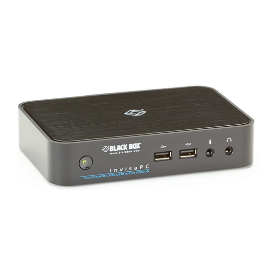
Chapter 3: InvisaPC Receivers Table 3-1. InvisaPC Receiver components. Number in Component Description Figures 3-1 through 3-3 Power LED Lights green when power is on 2, 6 (4) USB Type A connectors Link to USB devices (1) 3.5-mm connector Connects to microphone (1) 3.5-mm connector Connects to speakers (1) 2.5-mm barrel connector for power... -
Page 16: Chapter 4: Invisapc Transmitters
Chapter 4: InvisaPC Transmitters 4. InvisaPC Transmitters An InvisaPC Transmitter converts the video, audio, and USB connections of a PC or Workstation to a format that can be connect- ed and controlled over a TCP/IP network. The Transmitter connects to the DVI and USB ports of a PC or workstation. The Transmitter controls the connection to a remote Receiver and manages the flow of information to it. -
Page 17: Configuration Of Transmitter
(1) or (2) DVI input connectors Links to DVI input sources The Transmitter uses Black Box’s compound compression algorithm for video called Dynamic Content Optimized Compression (DCOC). This algorithm optimizes compression and latency on a frame-by-frame basis, depending on content in the video stream and on available network bandwidth. -
Page 18: Chapter 5: Invisapc Manager
Chapter 5: InvisaPC Manager 5. InvisaPC Manager (DTX1032-R) An InvisaPC Manager (DTX1032-R) managing a network of InvisaPC Receivers and Transmitters can also act as an InvisaPC Receiver. The DTX1032-R can manage 32 transmitters/receivers by default. It can manage up to 250 transmitter/receivers when an upgrade license(s) (DTX1032-LIC100 / DTX1032-LIC250) is added to DTX1032-R. -
Page 19: Chapter 6: Modes Of Operation
Chapter 6: Modes of Operation 6. Modes of Operation The InvisaPC system has various modes of operation such as Auto-Login, Auto-Connect, Private Connection, and Shared Connection Modes. The InvisaPC system can obtain their IP address data from a DHCP server in any of these modes or use static addresses. -
Page 20: Chapter 7: Application Examples
Chapter 7: Application Examples 7. Application Examples The InvisaPC system is built to be flexible so that it can be deployed in many different types of applications such as basic exten- sion, switching applications (sometimes called matrix), cloud-based desktops, control rooms, digital signage, and kiosk applica- tions and other applications in banking, financial services, broadcast, network operations, industrial, government and enterprise computing sectors. - Page 21 Chapter 7: Application Examples Transmitters Receivers Virtual Desktops Figure 7-2. InvisaPC Switching Example. 877-877-2269 | blackbox.com Page 21...
-
Page 22: Chapter 8: Invisapc Family
Chapter 8: InvisaPC Family 8. InvisaPC Family The InvisaPC system is composed of a family of Receivers, Transmitters, and Managers. The main difference between Receivers and Transmitters are on the number of video heads. The table below provides an example of products and part numbers. Table 8-1. -
Page 23: Chapter 9: Installation
Chapter 9: Installation 9. Installation 9.1 InvisaPC Receiver (DTX1000-R, DTX1002-R) Checklist Before installing your InvisaPC Receiver, refer to the list below to ensure that you have all the items necessary for installation: • InvisaPC Receiver • External power supply for the InvisaPC Receiver •... -
Page 24: Connect The Invisapc Receiver
NOTE: VGA or analog video monitors can be connected to the InvisaPC Receiver by using a DVI-D to VGA converter (not adapter). Contact Black Box for recommendation if needed. NOTE: When using the Receiver in single-head mode on a dual-head Receiver, the LEFT DVI connector is default as per the figure shown next. -
Page 25: Connect The Invisapc Transmitter
9. Turn on power for remote workstation and Transmitter. NOTE: Use only the power supply provided by Black Box. NOTE: When using a dual head Transmitter in single-head mode, the RIGHT DVI connector is default as per the figure shown next. -
Page 26: Connect The Invisapc Manager
Chapter 9: Installation Figure 9-2. InvisaPC Transmitter connections. Table 9-2. InvisaPC Transmitter Connections components. Number in Figure 9-2 Component Power LED 5V DC power inlet USB Type B connector RJ-45 port DVI video 9.8 Connect the InvisaPC Manager The recommended sequence to connect the Manager is: 1. - Page 27 Chapter 9: Installation Figure 9-3. InvisaPC Manager Connections. Table 9-3. InvisaPC Manager Connections components. Number in Figure 9-3 Component ON/OFF button USB Type A connector USB Type A connector Microphone Audio Line OUT 5-VDC Power IN Dual USB Type A connnector RJ-45 port DVI Video 877-877-2269 | blackbox.com...
-
Page 28: Chapter 10: Networked Installation
Chapter 10: Networked Installation 10. Networked Installation 10.1 Point-to-Point installation In a point-to-point configuration, no administrator setup of the InvisaPC Transmitter or the InvisaPC Receiver is required. This enables you to install the system quickly, directly out-of-the-box. However, in the point-to-point configuration, you can install only one InvisaPC Transmitter and InvisaPC Receiver pair on a subnet, and both must be on the same subnet unless a router is present in the network to span subnets. -
Page 29: Chapter 11: Operation Of The Invisapc System
Chapter 11: Operation of the InvisaPC System 11. Operation of the InvisaPC System Operating a workstation through the InvisaPC system is no different than working directly connected to a PC desktop. All peripherals operate as if directly connected, even though the workstation is located at a distance. 11.1 LED Identification Front panel There is one LED on the front panel of an InvisaPC unit (integrated into the power-button on the Receiver and Manager) - called... -
Page 30: Chapter 12: Osd Functions
Chapter 12: OSD Functions 12. OSD Functions The InvisaPC Receiver and Manager incorporate an On-Screen Display (OSD) that allows you to view information about the con- figuration of your system and potentially also allows for setting connections and configuration parameters such as the IP address, depending on the type of user. -
Page 31: Default Username And Password
Chapter 12: OSD Functions • System Preferences: This button has a drop down menu that allows the user to define system preferences for the InvisaPC Receiver. Figure 12-3 shows how the keyboard type can be selected. Figure 12-3. Setting Systems Keyboard Type. Help: This button opens a pop-up window with help on that screen. -
Page 32: Creating A New Connection
Chapter 12: OSD Functions Default_TX_192.168.1.22 NOTE: Default_TX is 192.168.1.22 Figure 12-4. Connection Screen. If the user is an Administrator type, the three buttons on the left (New, Edit, and Remove) will be displayed. These allow the user to create, edit, or remove connections. For Standard User types, no connections can be created, edited, or removed, so these but- tons are not displayed. - Page 33 Chapter 12: OSD Functions Figure 12-5. New Connection Window. The fields on this screen are: • Port: defines the port to be used for the RDP connection for connections via VM Direct or Broker. Uses 3389 by default; • Username: defines username to be used on a VM connection. Only used for connections via VM Direct or Broker. If left “blank” on VM Direct –...
-
Page 34: Connecting
Chapter 12: OSD Functions • Persistent Connection: When turned on, Persistent Connection will constantly try to connect to the Receiver until successful. This is useful when using InvisaPC for digital signage or an application that does not need a keyboard/mouse to stay connected to a defined source. -
Page 35: Preferences
Chapter 12: OSD Functions iii. Hot-Key Settings – allows changing of the active hot-key for keyboard short-cuts. iv. Timer Settings – allows setting of pre-emption timer and various inactivity timers 2. Network – allows administrator to change network parameters for the InvisaPC Receiver or Manager. 3. - Page 36 Chapter 12: OSD Functions The OSD Resolution is set to Auto by default, but can be changed to the available OSD resolutions if the user wants to set a specific resolution. This setting has no effect when connecting to an InvisaPC Transmitter. Click Apply button to save the change.
- Page 37 Chapter 12: OSD Functions The default hot-key is Print-Screen (PrntScrn). The alternatives are shown in the table. Click the Apply button to confirm a hot-key change. Table 12-1. Hotkey sequences. Sequence Action Print Screen (Default) -press Prnt Scrn key Ctrl + Ctrl -press Ctrl key twice within 1 second Alt + Alt -press Alt key twice within 1 second...
-
Page 38: Network
Chapter 12: OSD Functions 12.6.2 Network The network screen shown in Figure 12-11 allows an administrator to change the settings for the InvisaPC Receiver or Manager. The default network setting for the Receiver is a static IP address of 192.168.1.21. It has a Network Mask of 255.255.255.0 and a Gateway 192.168.1.1. - Page 39 Chapter 12: OSD Functions System Upgrade The InvisaPC Receiver or Manager can be upgraded from a USB Flash drive. Simply take the “firmware.clu” file and place it in the root directory of the flash drive. When you click the Upgrade button, the “valid” upgrade files on the USB drive are displayed. A valid file has the extension .clu –...
- Page 40 Chapter 12: OSD Functions The Web Access Server setting is used to allow access to a local copy of Active Domain server. If this setting is configured correctly, then if a user who if not configured in the local database attempts to login, the device will redirect the username and password to the local active directory installation and validate the user credentials.
-
Page 41: Export Settings
Chapter 12: OSD Functions Figure 12-16. Connection Broker Settings for CB Server. Tick the box “Connect Via Connection Broker Server” to enable connection using local Connection Broker Server. Then enter the following settings: 1. Enter in the domain name as defined on the local network. 2. -
Page 42: Configuring A Transmitter
The diagnostics provides information for Black Box to debug customer encountered issues. When this button is clicked the user is asked to save the diagnostics onto a memory stick in the Receiver unit. This file should be sent back to Black Box for analysis. - Page 43 Chapter 12: OSD Functions Figure 12-18. Transmitter Settings Configuration Window - Active IP Address. If the IP address of the Receiver and Transmitter are not on the same subnet, a router is required to allow them to communicate. This is true even when the Receiver “discovers” the Transmitter’s IP address. One way to avoid this is to change the Receiver address to be on the same subnet as the Transmitter, make the required configuration changes to the Transmitter, and then change the Receiver back to its required IP address.
- Page 44 Chapter 12: OSD Functions Transmitter Preferences The administrator can click the Transmitter Preferences to change Video Quality Setting or HID Configuration. When the Transmitter Preferences button is clicked the window shown in Figure 12-19 pops up. Figure 12-19. Transmitter Video Quality Settings 1.
-
Page 45: Managing Users
The Transmitter provides diagnostics information for Black Box to debug customer encountered issues. When this button is clicked the user is asked to save the diagnostics onto a memory stick in the Receiver unit. Send this file back to Black Box for analysis. -
Page 46: Add A User
Chapter 12: OSD Functions The InvisaPC Receiver and Manager have one default user – admin, which is a member of the administrator group. This user is defined by default and cannot be deleted. An InvisaPC Receiver or Manager can have a maximum of 32 users defined, unless in a manager domain with “upgrade”... - Page 47 Chapter 12: OSD Functions Default_TX_192.168.1.22 NOTE: Default_TX is 192.168.1.22 Figure 12-22. New User Window. When adding a new user, the following fields are used to define the user: • User Name: This is a unique name that uses 1–32 characters. The username can be any valid username for a Microsoft O/S. This means the username cannot contain “...
-
Page 48: Edit A User
Chapter 12: OSD Functions 12.7.3 Edit a User To edit a user, click on the Edit button. This causes the Edit-User window (shown in Figure 12-22) to be displayed. Figure 12-23. Edit User Window. This window allows the user privilege type, the permitted connections available, the password, and the auto-connect option to be changed. - Page 49 Chapter 12: OSD Functions When the Remove button is clicked, a pop-up window is displayed to prompt confirmation that this user is to be deleted. Click the Yes button to remove the user. Clicking the No button causes this action to be aborted and the user is not removed. NOTE: There must always be a user of the name admin in the InvisaPC system so the system can always be administrated.
-
Page 50: Chapter 13: Central Management
Chapter 13: Central Management 13. Central Management An InvisaPC system can be composed of just Receivers and Transmitters. In these types of systems – called unmanaged – there is no central management. Each device needs to be configured individually and upgraded individually. Often to keep the system in sync, the admin exports the configuration from one receiver and imports it to all other receivers using a USB Flash Drive. -
Page 51: Discovering And Adding Devices
Chapter 13: Central Management Figure 13-2. Device Tab Expanded. 13.1.1 Discovering and Adding Devices Using the Discover button is the best way to add devices to your managed devices. When you click the Discover button, the man- ager will look for unmanaged devices on the network. These devices will appear in the Discovered Devices section as shown next. This shows the MAC Address, IP Address, Net Mask, Gateway, Device Type, and the Discover State (managed, unmanaged, or orphaned) of the devices discovered. -
Page 52: Adding A Device Not On Your Network
Chapter 13: Central Management If a device has a managed state of “Orphaned”, then there is a conflict between the reported state on the Manager and that of the device. This may occur where the device was removed from the Manager’s database when the device was off-line, or if the Manager was restored to factory default settings. -
Page 53: Add Device Via Ip Address
Chapter 13: Central Management 13.1.4 Add Device via IP Address The Add Device section only applies to devices that are on the same network as the manager. The Add Device pop up window allows the administrator to add a device using the device’s IP address. Once you have entered in the device’s IP address and press next, a dialog box appears. -
Page 54: Licenses
Administrators can see the available Licenses in their system via the License button. They can also Import Licenses via USB Flash Drive. Place the upgrade file received from Black Box in the root directory of the flash drive. Press the License button. This will pop-up a window that shows the Serial Number of the unit and the current License limit. -
Page 55: Appendix A: Invisapc Video Resolutions Supported
Appendix A: InvisaPC Video Resolutions Supported Appendix A. InvisaPC Video Resolutions Supported The InvisaPC supports the resolutions listed below: • 640 x 480 @ 60 Hz • 640 x 480 @ 75 Hz • 800 x 600 @ 60 Hz •... -
Page 56: Appendix B: Configuring Windows 7 Virtual Machines For Invisapc
Appendix B: Configuring Windows 7 Virtual Machines for InvisaPC Appendix B. Configuring Windows 7 Virtual Machines for InvisaPC A few properties must be configured on a target Windows Virtual Machine for InvisaPC to connect with it. On the Windows Virtual Machine click on the Start button and launch a command window. Then launch group policy editor – gpedit.msc. -
Page 57: Appendix C: Overview Of Invisapc Network Protocols
For management purposes some other ports are used. The Black Box Discovery protocol used UDP Multicast Group 224.0.1.249 (port 39150). This is sent by the Manager to discover InvisaPC devices in the network. The router must allow UDP Multicast forwarding to allow devices on subnet different to where Manager is located to be discovered. - Page 58 NOTES 877-877-2269 | blackbox.com Page 58...
- Page 59 NOTES 877-877-2269 | blackbox.com Page 59...
- Page 60 About Black Box Black Box provides an extensive range of networking and infrastructure products. You’ll find everything from cabinets and racks and power and surge protection products to media converters and Ethernet switches all supported by free, live 24/7 Tech support available in 60 seconds or less.
Need help?
Do you have a question about the InvisaPC DTX1000-R and is the answer not in the manual?
Questions and answers