Black Box InvisaPC DTX1000-T Installation And User Manual
Hide thumbs
Also See for InvisaPC DTX1000-T:
- User manual (68 pages) ,
- Quick start manual (14 pages) ,
- Quick install manual (2 pages)
Table of Contents
Advertisement
Quick Links
Download this manual
See also:
User Manual
InvisaPC
DTX1000 System User Guide
™
Installation and User Manual
Order toll-free in the U.S.: Call 877-877-BBOX (outside U.S. call 724-746-5500)
Customer
FREE technical support 24 hours a day, 7 days a week: Call 724-746-5500 or fax 724-746-0746
Support
Mailing address: Black Box Corporation, 1000 Park Drive, Lawrence, PA 15055-1018
Information
Web site: www.blackbox.com • E-mail: info@blackbox.com
BLACK BOX
DTX1000-T
DTX1000-R
®
Advertisement
Table of Contents

Subscribe to Our Youtube Channel
Related Manuals for Black Box InvisaPC DTX1000-T


Summary of Contents for Black Box InvisaPC DTX1000-T
- Page 1 Order toll-free in the U.S.: Call 877-877-BBOX (outside U.S. call 724-746-5500) Customer FREE technical support 24 hours a day, 7 days a week: Call 724-746-5500 or fax 724-746-0746 Support Mailing address: Black Box Corporation, 1000 Park Drive, Lawrence, PA 15055-1018 Information Web site: www.blackbox.com • E-mail: info@blackbox.com...
- Page 2 Trademarks Used in this Manual Trademarks Used in this Manual Black Box and the Double Diamond logo are registered trademarks of BB Technologies, Inc. Any other trademarks mentioned in this manual are acknowledged to be the property of the trademark owners.
- Page 3 FCC and IC Statements Federal Communications Commission and Industry Canada Radio Frequency Interference Statements This equipment generates, uses, and can radiate radio-frequency energy, and if not installed and used properly, that is, in strict accordance with the manufacturer’s instructions, may cause inter ference to radio communication. It has been tested and found to comply with the limits for a Class A computing device in accordance with the specifications in Subpart B of Part 15 of FCC rules, which are designed to provide reasonable protection against such interference when the equipment is operated in a commercial environment.
- Page 4 Safety and EMC Approvals and Markings/Patent Information Safety and EMC Approvals and Markings FCC and CE Safety certifications and EMC certifications for this product are obtained under one or more of the following designa- tions: CMN (Certification Model Number), MPN (Manufacturer’s Part Number) or Sales Level Model designation. The designation that is referenced in the EMC and/or safety reports and certificates are printed on the label applied to this product.
-
Page 5: Table Of Contents
Table of Contents Table of Contents Specifications ....................................7 Chapter 1: Product Overview ..............................9 Introduction ...................................9 InvisaPC System Features ...............................9 Security ..................................9 Flash Upgradable ................................9 IP Addressing ................................10 Support for Keyboards, Mice, and Mass Storage Devices .................... 10 Video ................................... 10 Transmitter Features ................................ - Page 6 Table of Contents Connecting ...................................... 37 Edit Connection ....................................37 Remove Connection ..................................38 Managing Users ......................................39 Add a User .......................................39 Edit a User ....................................... 41 Remove a User ....................................42 Control Tab ....................................... 43 Network ......................................44 System ......................................45 System Upgrade ....................................45 Resolution ......................................46 Password ......................................
-
Page 7: Specifications
Technical Specifications Technical Specifications Approvals Unit: FCC, CE, RoHS2; Power Supply: FCC, CE, RoHS2, TUV, UL ® DDC Support DTX1000-T (Transmitter): Internal DDC table Default Settings DTX1000-T (Transmitter): IP Address: 192.168.1.22; DTX1000-R (Receiver): IP Address: 192.168.1.21; Username: admin; Password: N/A, blank password by default Distance DTX1000-T (Transmitter): Distance (maximum) from CPU to TX: 16 feet, DVI-D and USB limitations;... - Page 8 Instructions This symbol is intended to alert the user to the presence of important operating and maintenance (servicing) instructions in the literature accompanying the appliance. Dangerous Voltage This symbol is intended to alert the user to the presence of uninsulated dangerous voltage within the product’s enclosure that may be of sufficient magnitude to constitute a risk of electric shock to persons.
-
Page 9: Chapter 1: Product Overview
Chapter 1: Product Overview Chapter 1 – Product Overview Introduction The InvisaPC system, which includes a transmitter and a receiver, provides users with a full desktop experience from anywhere on the corporate TCP/IP network, while maintaining the desktop securely housed in a corporate data center. The desktops accessed can be a physical PC / workstation or can be a virtual desktop hosted on a server. -
Page 10: Ip Addressing
Chapter 1: Product Overview IP addressing The InvisaPC Receiver and Transmitter are IP-addressable devices, giving you the flexibility to locate workstations anywhere within your enterprise and at any distance from your desktop users. The InvisaPC receiver and transmitter use standard network protocols to transfer data between the remote workstation and the peripheral devices located at the user’s desk. -
Page 11: Transmitter Features
Chapter 1: Product Overview The InvisaPC supports the resolutions listed below: • 640 x 480 @ 60 Hz • 800 x 600 @ 60 Hz • 1024 x 768 @ 60 Hz • 1600 x 1200 @ 60 Hz • 1280 x 1024 @ 60 Hz •... -
Page 12: Receiver Features
Chapter 1: Product Overview Receiver features The InvisaPC Receiver enables the desktop user’s peripherals to connect to the target workstation or virtual desktop via a network connection to the Transmitter connected to the target workstation or to the server hosting the virtual desktop. Multiplatform support InvisaPC is compatible with the following operating systems: ®... -
Page 13: Operations, Administration, And Maintenance
Chapter 1: Product Overview Operations, administration, and maintenance The InvisaPC Receiver’s OSD allows you to perform administration and maintenance tasks for both the InvisaPC Receiver and Transmitter. Examples of tasks you can perform include creation of user access rights, configuration of network settings, and firmware Flash upgrades. Virtual USB (USB re-direction) USB devices can be attached to the InvisaPC Receiver and function as if they are directly connected to the remote workstation or virtual desktop. -
Page 14: Auto-Login
Chapter 1: Product Overview Auto-Login In Auto-Login Mode, turning on the InvisaPC Receiver automatically causes it to login as a pre- defined user. The user is presented with the available connections that can be made to remote workstations/virtual desktops. Auto-Connect In Auto-Connect Mode, when a user logs-in to the InvisaPC Receiver, it causes an automatic connection to their allocated workstation or virtual desktop (this connection is pre-defined and triggered by a successful login). - Page 15 Chapter 1: Product Overview Figure 1 - InvisaPC System (basic extender) Table 1.1: Figure 1 Descriptions Number Description PC or Workstation InvisaPC Transmitter IP network – 100Mbps InvisaPC Receiver User Peripherals – keyboard, mouse, monitor 724-746-5500 l www.blackbox.com...
- Page 16 Chapter 1: Product Overview In Figure 2, a larger scale system is shown. This is referred to as an unmanaged matrix type of deployment. In this deployment, there are several Receivers and Transmitter as well as virtual desktops. Figure 2 - InvisaPC Systems (Unmanaged Matrix) 724-746-5500 l www.blackbox.com...
- Page 17 Chapter 1: Product Overview To avoid potentially fatal shock hazard and possible damage to equipment, please observe the following precautions: ∞ Test AC outlets at the workstation and monitor for proper polarity and grounding. ∞ Use only with grounded outlets at both the workstation and monitor. When using a backup Uninterruptible Power Supply (UPS), power the workstation and the transmitter from the same supply.
-
Page 18: Chapter 2: Installation
CHAPT ER Chapter 2 - Installation Installing the InvisaPC Receiver Before installing your InvisaPC Receiver, refer to the list below to ensure that you have all the items necessary for installation. Requirements to install the InvisaPC Receiver InvisaPC Receiver External power supply for the InvisaPC Receiver IEC power cord InvisaPC Quick Installation Guide (QIG) 724-746-5500 l www.blackbox.com... -
Page 19: Mounting Option
Chapter 2: Installation Mounting option The InvisaPC Receiver mounts to the rear of a flat panel monitor via a mounting plate accessory. Installing the InvisaPC Transmitter Before installing your InvisaPC Transmitter, refer to the list below to ensure that you have all the items necessary for installation. -
Page 20: Installation Options
Chapter 2: Installation Installation options CAUTION: To reduce the risk of electric shock or damage to your equipment, disconnect the power from the InvisaPC Receiver or Transmitter by unplugging the power supply from the electrical outlet. To reduce the risk of electric shock or damage to your equipment, turn on the remote workstation and the InvisaPC Transmitter in the order described in the following procedures. -
Page 21: To Connect The Invisapc Transmitter
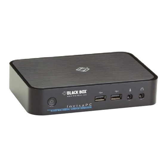
Chapter 2: Installation Table 2.1: Figure 3 Descriptions Number Description PC or Workstation InvisaPC Transmitter IP network – 100Mbps InvisaPC Receiver User Peripherals – keyboard, mouse, monitor To connect the InvisaPC Transmitter: Before connecting the InvisaPC Transmitter to the remote workstation, ensure that the resolution and the refresh rate of the remote workstation are supported by the InvisaPC Transmitter. - Page 22 Chapter 2: Installation I n v i s a P C BLACK BOX DIGITAL DESKTOP EXTENSION Figure 4 - InvisaPC Transmitter Connections Table 2.2: Figure 4 Descriptions Number Type of Connector Power LED 5V DC Power Inlet USB Type B Connector...
-
Page 23: To Connect The Invisapc Receiver
Chapter 2: Installation To connect the InvisaPC Receiver: Connect your keyboard, monitor, mouse, and other peripheral cables to the appropriately labeled ports on the the InvisaPC Receiver. Connect the UTP cable to the RJ-45 port on the back of the InvisaPC Receiver. Turn on the InvisaPC Receiver. - Page 24 Chapter 2: Installation Table 2.3: Figure 5 Descriptions Number Type of Connector On/Off Button USB Type A Connector USB Type A Connector Microphone Audio Line Out 5V DC Power In Dual USB Tupe A Connector RJ-45 Port DVI Video 724-746-5500 l www.blackbox.com...
-
Page 25: Connecting Power
The InvisaPC Receiver features an external power supply. A DC power jack is located on the rear of the InvisaPC Receiver. NOTE: Use only the power supply provided by Black Box. Plug the external power supply’s 2.5 mm connector into the DC power jack on the rear of the InvisaPC Receiver. - Page 26 Chapter 2: Installation Figure 6 - Point-to-point installation Figure 2.4: Networked Installation Number Description PC or Workstation InvisaPC Transmitter IP network – 100Mbps InvisaPC Receiver User Peripherals – keyboard, mouse, monitor The InvisaPC Receiver has been preconfigured with factory-default network settings. If you install only one InvisaPC Receiver and one InvisaPC Transmitter on a subnet, you do not need to change these default network settings.
-
Page 27: To Install The Invisapc System On A Network
Chapter 2: Installation Table 2.5: InvisaPC System Default Network Settings Default Gateway Component IP Address Type Subnet Mask InvisaPC 192.168.1.21 Static 0.0.0.0 255.255.255.0 Receiver InvisaPC 192.168.1.22 Static 0.0.0.0 255.255.255.0 Transmitter With the InvisaPC Transmitter already connected to the remote workstation, connect it to the network via the unit's RJ-45 connector. -
Page 28: Chapter 3: Operations
CHAPT ER Chapter 3 - Operations Overview Operating a workstation or virtual desktop through the InvisaPC system is no different than working directly connected to a PC desktop. All peripherals operate as if directly connected, even though the workstation/virtual desktop is located at a distance. While the InvisaPC system default settings will work in most environments, you may configure the settings to better fit your installation via the On-Screen Display (OSD) on an InvisaPC Receiver. -
Page 29: Accessing The System
Chapter 3 : Operations Table 3.1: RJ-45 Connector LEDs Indication Meaning LED 1 Green on Linked at 100 Mbps Green off Linked at 10Mbps or No Link LED 2 Yellow Static Linked but no activity Yellow flashing Transmit/receive activity Accessing the System A connection is established using the OSD on an InvisaPC Receiver. -
Page 30: User Types
Chapter 3 : Operations User Types The InvisaPC system defines three classes of users: Administrator – users of this class have full rights to configure the system. They can create/modify/delete new users and connections, change network settings, etc. Power-User – users of this class can configure the resolution of the connection for virtual desktop connections and to make connections. -
Page 31: Log-On
Chapter 3 : Operations Log-on A user must log-on to the InvisaPC Receiver to configure and manage the InvisaPC system. The log-on screen is shown in . The username defines the access rights and Figure 7 configuration available to the user. Figure 7 - InvisaPC Receiver OSD - Login-on screen The fields on this screen are: ∞Username: the username to log-on as defined by the Admin. -
Page 32: Default Username And Password
Chapter 3 : Operations ∞ System Preferences: This button has a drop down menu that allows the user to define system preferences for the InvisaPC Receiver. Figure 9 shows how the keyboard type can be selected. Figure 9 - Setting System Keyboard type ∞... -
Page 33: Connections Screen
Chapter 3 : Operations Connections Screen When a user successfully logs-on to the InvisaPC Receiver, the Connection screen is displayed. This is shown in Figure 10. The connections that a user can make are listed in the connection window (Examples “connection1”, “connection2” and “connection3” are shown in Figure 10). The user logged on is shown in the top right corner of the OSD –... - Page 34 Chapter 3 : Operations By default there is one connection called “Default Tx - 92.168.1.22”, which defines a connection to an InvisaPC Transmitter with its factory defaults. A maximum of 32 connections can be defined for an InvisaPC Receiver and these connections can be shared by users as defined by an administrator (different users can have the same connection).
-
Page 35: Creating A New Connection
Chapter 3 : Operations Creating a New Connection To allow an InvisaPC Receiver to connect to a target – whether Virtual Desktop or an InvisaPC Transmitter – an administrator must create a connection. The administrator clicks on the New button on the Connections screen. This causes the New Connections pop-up window to appear as shown in Figure 11. - Page 36 Chapter 3 : Operations ∞Port: the TCP port number to be used to establish connection to the InvisaPC transmitter or the Virtual Desktop. The default is 3389. A user can change this field if required to match their network/firewall requirements. ∞Username: defines the username to be used to log-on to a virtual desktop.
-
Page 37: Connecting
Chapter 3 : Operations Connecting To make a connection, the user highlights the required “connection” in the window and then clicks on the “ Connect” button. Alternatively, a user can double click on the connection. This action causes the InvisaPC Receiver to attempt to connect to the target remote workstation / virtual desktop. -
Page 38: Remove Connection
Chapter 3 : Operations Figure 12 - Edit Connections Pop-up window The fields are the same as defined on page 35. The administrator changes required fields and clicks Save to have them take effect or Cancel to discard any changes. Remove Connection To remove or delete a connection, an administrator highlights a connection in the list and then clicks on the Remove button on the Connections screen (shown in Figure 10). -
Page 39: Managing Users
Chapter 3 : Operations Managing Users Users are defined in the InvisaPC system to provide rights to manage the system, rights to connect to different target devices and set parameters for connections. There are three types of users that can be created in an InvisaPC system. Administrator –... - Page 40 Chapter 3 : Operations Figure 14 - New User Window When adding a new user, the following fields are applied: ∞User Name: This is a unique name that uses 1–32 characters. The username can be any valid username for a Microsoft O/S. This means the username cannot contain “ ”/ \ [ ] : ; | = , + * ? <...
-
Page 41: Edit A User
Chapter 3 : Operations This Connect to at Login is only saved when the Apply button is clicked. If not clicked and another tab is selected, the changes are ignored. If not ticked, no automatic connection is made on log-in. Once the new user fields have been filled out, the Save button must be clicked to create the new user. -
Page 42: Remove A User
Chapter 3 : Operations The default “admin” account gets access to all connections; this list cannot be modified. Other administrator-type users can have their connection list modified. Once the changes have been made for a user, they only become active once the Save button has been clicked. -
Page 43: Control Tab
Chapter 3 : Operations Control Tab The Control Tab on the OSD provides the ability for an Administrator to change configuration of Figure 17 InvisaPC systems. The Control Tab is shown in Figure 17 - Control Tab There are six functions that can be accessed on this tab: 1. -
Page 44: Network
Chapter 3 : Operations Network The network screen shown in Figure 18 allows an administrator to change the settings for the InvisaPC Receiver. The default network setting for the Receiver is a static IP address of 192.168.1.21. If DHCP is selected, the receiver gets its IP address from the DHCP server. The Apply button must be clicked to confirm any changes to network settings. -
Page 45: System
Chapter 3 : Operations System The System screen shown in Figure 19 allows an administrator to upgrade the firmware in the InvisaPC Receiver, reset it to factory defaults, and import/export the configuration to an external USB drive. Figure 19 - System Screen On this screen, the administrator can set the resolution for the OSD. -
Page 46: Resolution
Chapter 3 : Operations Figure 20 - Upgrade Files Once the administrator has selected the file and clicked Ok, the system checks that the selected file has no errors prior to upgrading the InvisaPC Receiver. The configuration of the unit is preserved through the upgrade. -
Page 47: Password
Chapter 3 : Operations Figure 21 - Resolution Screen Password The Password button when clicked allows the current user’s password to be changed. This button is only visible to Administrators and Power-Users. Transmitter Configuration The Transmitter button on the Control Tab allows administrators to change the configuration of an InvisaPC Transmitter (this button is not visible to Power-users and Standard-Users). - Page 48 Chapter 3 : Operations 1.Transmitter Information 2.Transmitter firmware upgrade 3.Transmitter restore factory defaults 4.Transmitter re-boot 5.Transmitter discovery 6.Discover Transmitter IP address 724-746-5500 l www.blackbox.com...
-
Page 49: Configuring A Transmitter
Chapter 3 : Operations Configuring a Transmitter To configure a Transmitter, the IP address must be defined for the target Transmitter. This is called setting an active Transmitter IP address. When there is no active IP address defined, the TX Setting window has all the buttons greyed out except for the Apply and Discover buttons as shown in Figure 22. - Page 50 Chapter 3 : Operations There are two ways to define an active IP address. One is to enter the Transmitter’s IP address directly and click the Apply button. This only causes a check that the IP address is valid and not that we can communicate with this transmitter (or that the device at that IP address is a transmitter).
-
Page 51: Transmitter Information
Chapter 3 : Operations Transmitter Information The Information button provides transmitter related information such as Device Model, Serial Number, MAC address, and current Firmware Version to the administrator. If the active IP address is not the address of a valid InvisaPC Transmitter or this address is unreachable, an error message is returned. -
Page 52: Transmitter Network Settings
Chapter 3 : Operations Transmitter Network Settings The administrator can click the Network button to cause the Transmitter Network Settings window to be displayed as shown in Figure 24. This example figure has no active IP address defined. If previously defined, it is maintained when bringing up this window. Optionally the administrator can choose to target a different transmitter by entering a new Transmitter IP Address and clicking the Apply button. -
Page 53: Hot-Key
Chapter 3 : Operations If the new IP address for the InvisaPC Transmitter is on a different subnet to the Receiver, the Receiver will not be able to communicate with it without going through a router. This is even the case on a point-to-point link between the Transmitter and Receiver. - Page 54 Chapter 3 : Operations Table 3.2: OSD Hotkey Sequences Hotkey Sequences Print Screen (Default) - press PrnScrn key Ctrl + Ctrl - press Ctrl key twice within 1 sec Alt + Alt - press Alt key twice within 1 sec Shift + Shift - press Shift key twice within 1 sec Open OSD: “Hotkey”...
-
Page 55: Appendix A. Factory Defaults
Ap pen d ix Appendix A- Factory Defaults This appendix defines the settings for various parameters for InvisaPC Receivers and Transmitters when they ship from the factory or when an administrator requests a reset to factory defaults. InvisaPC Receiver Defaults Network Settings Defaults ∞IP address configuration (Static or DHCP): Static ∞... -
Page 56: Hot-Key Default
Hot-key Default ∞Active Hot-key: Print-Screen (PrntScrn) Connection Modes ∞Auto-Login: Admin (login in as Admin) ∞Auto-Connect: not enabled ∞Connection Type: Private InvisaPC Transmitter Defaults Network Settings Defaults ∞IP address configuration (Static or DHCP): Static ∞ IP Address: 92.168.1.22 ∞ Default Gateway: 0.0.0.0 ∞... -
Page 57: Discovering A Transmitter
Discovering a Transmitter: If the transmitter IP address is lost or needs to be configured, you can perform the following steps to discover the transmitter. 1. Connect the transmitter and receiver together using a straight CATx cable. 2. Power down the transmitter, but leave the receiver in the ON state. 3. - Page 58 About Black Box Black Box provides an extensive range of networking and infrastructure products. You’ll find everything from cabinets and racks and power and surge protection products to media converters and Ethernet switches all supported by free, live 24/7 Tech support available in 30 seconds or less.
Need help?
Do you have a question about the InvisaPC DTX1000-T and is the answer not in the manual?
Questions and answers