Black Box Agility Zero-U ACR500DP-T Quick Start Manual
Agility zero u series
Hide thumbs
Also See for Agility Zero-U ACR500DP-T:
- User manual (59 pages) ,
- Quick start manual (2 pages)
Table of Contents
Advertisement
Quick Links
Download this manual
See also:
User Manual
Advertisement
Table of Contents

Related Manuals for Black Box Agility Zero-U ACR500DP-T


Summary of Contents for Black Box Agility Zero-U ACR500DP-T
- Page 1 QUICK START GUIDE ACR500DP-T ACR500DV-T AGILITY ZERO U TRANSMITTER 24/7 TECHNICAL SUPPORT AT 877.877.2269 OR VISIT BLACKBOX.COM...
-
Page 2: Initial Configuration
WELCOME This quick start guide covers some of the key points of the Agility Zero U Transmitter. Full user details and setup instructions can be found within the Support section at www.blackbox.com INITIAL CONFIGURATION Please see the next page for Connection details. Agility units can be linked in two main ways: Direct or Networked. -
Page 3: Networked Linking
NETWORKED LINKING Agility Gigabit Agility Agility Ethernet Zero U TX Agility Where Agility units are connected via networked links, you can either configure them individually, or configure them collectively using an iPATH Manager: • Configuring networked Agility units individually - You need to specify the network addresses of the Agility units so that they can locate each other. - Page 4 • Configuring networked Agility units collectively - The iPATH Manager allows you to configure, control and coordinate any number of Agility transmitters and receivers from a single application. See blackbox.com for details. IMPORTANT: When using an iPATH Manager to configure Agility units, it is vital that all units that you wish to locate and control are set to their factory default settings.
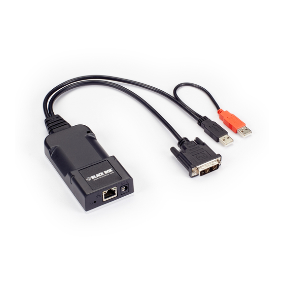
- Page 5 CONNECTIONS Cable tie mounting Status slot indicators (see page 9) DVI-D (or DisplayPort) connector input Optional external power input Reset button (see page 8) Ethernet port (plus indicators) - Either link Red USB plug provides directly to an Agility power only when the receiver or via a network external power adapter Black USB plug provides...
-
Page 6: Browser-Based Configuration Utility
BROWSER-BASED CONFIGURATION UTILITY Use this utility when configuring the Agility Zero U Transmitter to work with Agility receivers which are linked via a network. You will need to use a computer connected to the same network as the Agility Zero U Transmitter (you can also connect them directly). - Page 7 BROWSER-BASED CONFIGURATION UTILITY (CONT.) The opening page of the Agility configuration utility:...
- Page 8 TO PERFORM A MANUAL FACTORY RESET A factory reset returns the Agility Zero U Transmitter to its default configuration. 1 Power on the Agility Zero U Transmitter module. 2 Use a narrow implement (e.g. a straightened-out paper clip) to press- and-hold the recessed reset button on the front panel for roughly fifteen seconds, until the status indicators turn blue (Note: alternating red/green indications will occur during the fifteen second period...
- Page 9 MAIN STATUS INDICATORS • Off No power. • Green Operating - Video, USB and network link all present. • Orange Operating - But video, USB and/or network link missing. • Red (momentarily) Unit is booting up, or (consistently) Unit has failed, try rebooting. • Red/green flashing Unit is in backup mode. • Blue Factory reset has been activated. • Red/blue flashing Unit is in upgrade mode. • Fast green flash Unit is in identify mode.
-
Page 10: Safety Information
SAFETY INFORMATION • For use in dry, oil free indoor environments. • Not suitable for use in hazardous or explosive environments or next to highly flammable materials. • No user serviceable parts are contained within the module - do not dismantle. RADIO FREQUENCY ENERGY All interface cables used with this equipment must be shielded in order to maintain compliance with radio frequency energy emission regulations and ensure a suitably high level of immunity to electromagnetic disturbances. - Page 11 with the manufacturer’s instructions, may cause interference to radio communication. It has been tested and found to comply with the limits for a class A computing device in accordance with the specifications part 15 of FCC rules, which are designed to provide reasonable protection against such interference when the equipment is operated in a commercial environment. Operation of this equipment in a residential area may cause interference, in which case the user at his own expense will be required to take whatever measures may be necessary to correct...
- Page 12 COPYRIGHT 2018 BLACK BOX CORPORATION. ALL RIGHTS RESERVED.
Need help?
Do you have a question about the Agility Zero-U ACR500DP-T and is the answer not in the manual?
Questions and answers