Table of Contents
Advertisement
Quick Links
Advertisement
Table of Contents

Related Manuals for Mindray PM-60Vet


Summary of Contents for Mindray PM-60Vet
- Page 1 PM-60Vet Pulse Oximeter Operator’s Manual...
-
Page 3: Revision History
Revision number: 1.1 Release time: 2007-11 © Copyright 2007 Shenzhen Mindray Bio-Medical Electronics Co., Ltd. All rights reserved. WARNING Federal Law (USA) restricts this device to sale by or on the order of a... - Page 4 FOR YOUR NOTES...
- Page 5 This manual may refer to information protected by copyrights or patents and does not convey any license under the patent rights of Mindray, nor the rights of others. Mindray intends to maintain the contents of this manual as confidential information.
- Page 6 Manufacturer’s Responsibility All information contained in this manual is believed to be correct. Mindray shall not be liable for errors contained herein nor for incidental or consequential damages in connection with the furnishing, performance, or use of this manual. Mindray is responsible for the effects on safety, reliability and performance of this...
- Page 7 Exemptions Mindray's obligation or liability under this warranty does not include any transportation or other charges or liability for direct, indirect or consequential damages or delay resulting from the improper use or application of the product or the use of parts or accessories not approved by Mindray or repairs by people other than Mindray authorized personnel.
- Page 8 Return Policy In the event that it becomes necessary to return a unit to Mindray, follow the instructions below. Return authorization. Contact the Customer Service Department and obtain a Customer Service Authorization number. This number must appear on the outside of the shipping container.
- Page 9 Contact Information Manufacturer: Shenzhen Mindray Bio-Medical Electronics Co., Ltd. Address: Mindray Building, Keji 12th Road South, Hi-tech Industrial Park, Nanshan, Shenzhen 518057, P.R. China Tel: +86 755 26582479 +86 755 26582888 Fax: +86 755 26582934 +86 755 26582500 Website: www.mindray.com EC-Representative: Shanghai International Holding Corp.
- Page 10 FOR YOUR NOTES VIII...
- Page 11 Preface Manual Purpose This manual contains the instructions necessary to operate the product safely and in accordance with its function and intended use. Observance of this manual is a prerequisite for proper product performance and correct operation and ensures patient and operator safety.
- Page 12 FOR YOUR NOTES...
-
Page 13: Table Of Contents
Contents 1 Safety ......................... 1-1 1.1 Safety Information ..................1-1 1.1.1 Dangers ....................1-2 1.1.2 Warnings .................... 1-2 1.1.3 Cautions ..................... 1-3 1.1.4 Notes ....................1-4 1.2 Equipment Symbols ..................1-5 2 The Basics........................2-1 2.1 Introduction..................... 2-1 2.1.1 Intended Use ..................2-1 2.1.2 Contraindications ................ - Page 14 4.4 Adjust the Screen Brightness ................4-3 4.5 Changing the Language .................. 4-3 4.6 Setting the Clock..................... 4-4 4.7 Adjusting the Volume..................4-4 4.7.1 Setting the Beat Volume..............4-4 4.7.2 Setting the Key Volume ..............4-5 4.8 Entering/Exiting the Demo Mode..............4-5 4.9 Checking the Version ..................
- Page 15 6.4.1 Switching On/Off SpO and PR Alarms..........6-3 6.4.2 Setting Alarm Level ................6-3 6.4.3 Adjusting the Alarm Limits ............... 6-4 6.4.4 Switching On/Off the Alarm Limit Display ........6-4 6.4.5 Setting SpO Sensitivity..............6-4 6.5 Measurement Limitations ................6-5 7 Data Management ....................
- Page 16 B EMC......................... B-1 C Factory Defaults ..................... C-1 C.1 Alarm Setup ....................C-1 C.2 System Setup ....................C-2 C.3 SpO Setup..................... C-2 D Alarm Messages ...................... D-1 D.1 Physiological Alarm Messages ..............D-1 D.2 Technical Alarm Messages................D-1 E Symbols and Abbreviations ................... E-1 E.1 Units........................E-1 E.2 Symbols ......................E-2 E.3 Abbreviations....................E-3...
-
Page 17: Safety
Safety 1.1 Safety Information DANGER Indicates an imminent hazard that, if not avoided, will result in death or serious injury. WARNING Indicates a potential hazard or unsafe practice that, if not avoided, will result in death or serious injury. CAUTION Indicates a potential hazard or unsafe practice that, if not avoided, could result in minor personal injury or product/property damage. -
Page 18: Dangers
1.1.1 Dangers There are no dangers that refer to the product in general. Specific “Danger” statements may be given in the respective sections of this manual. 1.1.2 Warnings WARNINGS Before putting the system into operation, verify that the equipment, connecting cables and accessories are in correct working order and operating condition. -
Page 19: Cautions
To avoid inadvertent disconnection, route all cables in a way to prevent a stumbling hazard. Wrap and secure excess cabling to avoid risk of entanglement or strangulation by animals or personnel. 1.1.3 Cautions CAUTIONS To ensure animal safety, use only parts and accessories specified in this manual. -
Page 20: Notes
1.1.4 Notes NOTES Put the equipment in a location where you can easily see the screen and access the operating controls. Keep this manual in the vicinity of the equipment so that it can be obtained conveniently when needed. The software was developed in compliance with IEC60601-1-4. The possibility of hazards arising from software errors is minimized. -
Page 21: Equipment Symbols
1.2 Equipment Symbols Direct Current (DC) Attention: Consult accompanying documents (this manual). Auxiliary output connector Audio pause Battery door locked/unlocked Power supply connector Left/Right button Power button Up button Down button Date of manufacture Manufacturer European community representative Serial number Safety Class II equipment Type BF applied part, defibrillation protected... - Page 22 The following definition of the WEEE label applies to EU member states only. This symbol indicates that this product should not be treated as household waste. By ensuring that this product is disposed of correctly, you will help prevent bringing potential negative consequences to the environment and human health.
-
Page 23: The Basics
The Basics 2.1 Introduction 2.1.1 Intended Use The pulse oximeter is intended for continuously monitoring, spot checking, displaying, storing and transferring oxygen saturation and pulse rate of single dog, cat and other animals. WARNING This pulse oximeter is intended for use only by clinical professionals or under their guidance. -
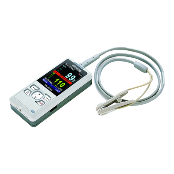
Page 24: Main Unit
2.2 Main Unit 2.2.1 Front View Display screen Power button Press this button to turn the pulse oximeter on after the batteries are installed. Press and hold it for 2 seconds to turn the pulse oximeter off. Power indicating lamp It is a LED that lights green and yellow. - Page 25 Green: when the pulse oximeter is placed in the Charger stand and the AC mains is connected, or when the battery is fully charged if a lithium battery is used. Yellow: when a lithium ion battery is used and is being charged. Off: When the AC mains is not connected.
-
Page 26: Rear View And Right View
2.2.2 Rear View and Right View Multifunctional connector It is used to connect an SpO sensor to measure the oxygen saturation or connect a personal computer through a PC communication cable to export the trend data. Speaker Battery door Cord hole Infrared port It is a port through which a personal computer is communicated to export data in real time. -
Page 27: Display Views
2.3 Display Views The following figures show the layout of the wave screen and the normal screen. Wave screen Normal screen Waveform Area This area displays Pleth waveform (Pleth). The label of this waveform is shown at the top left corner. area Technical alarm area This area shows the technical alarm message, prompt message and the pulse... -
Page 28: Spo Area
PR area Physiological alarm area This area shows physiological alarm messages. When multiple alarms come, they will be displayed circularly. Information area QuickKeys area This area contains QuickKeys that give you fast access to functions. 2.3.1 SpO Area label unit high alarm limit low alarm limit Oxygen saturation reading... -
Page 29: Pr Area
2.3.2 PR Area PR label PR unit PR high alarm limit PR low alarm limit Pulse rate reading 2.3.3 Information Area Animal ID Animal category Animals are classified into three categories: dog, cat and others. Real-time data exporting symbol This symbol appears when data is being exported in real-time through the infrared port. - Page 30 FOR YOUR NOTES...
-
Page 31: Getting Started
Getting Started 3.1 Unpacking and Checking Before unpacking, examine the packing case carefully for signs of damage. If any damage is detected, contact the carrier. If the packing case is intact, open the package and remove the equipment and accessories carefully. Check all materials as per the packing list and check for any mechanical damage. -
Page 32: Environmental Requirements
3.2 Environmental Requirements The operating environment of the equipment must meet the requirements specified in this manual. When the equipment is moved from one place to another, condensation may occur as a result of temperature or humidity difference. In this case, never start the system before the condensation disappears. -
Page 33: Shutting Off The Pulse Oximeter
WARNING Do not use the pulse oximeter for animal monitoring if it is mechanically damaged or appears abnormal. Contact your service personnel or us. 3.4 Shutting Off the Pulse oximeter To shut off the pulse oximeter, Confirm that the animal monitoring is finished. Disconnect the SpO extension cable from the pulse oximeter. - Page 34 FOR YOUR NOTES...
-
Page 35: Basic Operations
Basic Operations 4.1 Selecting the Work Mode The pulse oximeter is designed to operate in the continuous monitoring and spot-checking mode. The continuous monitoring mode is intended for long-term monitoring. This mode is normally selected when the patient is in hospital or under transport. -
Page 36: Admitting A Patient
4.2 Admitting a Patient WARNING Be sure to select correct patient category setting for your patient before measurement. Wrong patient category may result in patient hazard due to improper alarm limits. 4.2.1 Continuous Monitoring Mode In the continuous monitoring mode, to admit a patient, Select [Menu]→[Patient Info.]. -
Page 37: Selecting The Screen
4.3 Selecting the Screen To select a screen to be viewed, Select [Menu]→[System]. Select [Screen] and toggle between [Normal] and [Wave]. 4.4 Adjust the Screen Brightness To adjust the screen brightness, Select [Menu]→[General Setup]. Adjust [Brightness]: You can set the screen brightness to a value between 1 and 10. -
Page 38: Setting The Clock
4.6 Setting the Clock To set the clock, Select [Menu]→[System]→[Maintenance >>]→enter the required password. Select [Clock >>], and then set [Date] and [Time]. Select [Format >>]. In the [Format] menu, Set [Date Format] to [yyyy-mm-dd], [mm-dd-yyyy] or [dd-mm-yyyy]. Set [Time Format] to [24 h] or [12 h]. Press the Right button to return to the previous menu in the spot-checking mode, or press the Right button and follow the prompt in the continuous monitoring mode. -
Page 39: Setting The Key Volume
4.7.2 Setting the Key Volume To set the key volume, Select [Menu]→[General Setup]. Set [Key Vol] to a value between 0 and 10. 0 means the key volume is turned off, and 10 is the maximum volume. 4.8 Entering/Exiting the Demo Mode To enter the demo mode: Select [Menu]→[System]→[Maintenance >>]→enter the required password. -
Page 40: Entering/Exiting The Standby Mode
4.10 Entering/Exiting the Standby Mode 4.10.1 Entering the Standby Mode In the spot-checking mode, in situations where reviewing or exporting trend data is not performed, the pulse oximeter will automatically enter the standby mode if no button operation and SpO2 signal are detected for 1 minute and no "Battery Too Low" alarm occurs. -
Page 41: Setting Auto Poweroff
4.11 Setting Auto Poweroff In the spot-checking mode, you can select to shut off the pulse oximeter automatically: Select [Menu]→[System]→[Maintenance >>]→enter the required password. Select [User Maintenance >>], and then select [Auto Quit] to toggle between: [Allowed]: The pulse oximeter will shut down automatically if no button operation and SpO signal are detected for 5 minutes in the standby mode. -
Page 42: Saving The User Configuration
4.12.2 Saving the User Configuration You can change the pulse oximeter’s settings and save the changed settings as user configuration. To save the user configuration, Select [Menu]→[System]→[Maintenance >>]→enter the required password. Select [User Maintenance >>]→[Save as User Conf.]. The user configuration will be saved according to the current work mode and patient category. -
Page 43: Alarms
Alarms Alarms, triggered by a vital sign that appears abnormal or by technical problems of the pulse oximeter, are presented to the user by visual and audible alarm indications. 5.1 Alarm Categories By nature, the pulse oximeter’s alarms can be classified into three categories: physiological alarms, technical alarms and prompt messages. -
Page 44: Alarm Levels
5.2 Alarm Levels By severity, the pulse oximeter’s physiological alarms can be classified into three categories: high level alarms, medium level alarms and low level alarms. High level alarms Indicate that the patient is in a life threatening situation and an emergency treatment is demanded. -
Page 45: Alarm Lamp
5.3.1 Alarm Lamp If a technical or a physiological alarm occurs, the alarm lamp will flash. The flashing color and frequency match the alarm level as follows: High level alarms: the lamp quickly flashes red. Medium level alarms the lamp slowly flashes yellow. Low level alarms: the lamp turns yellow without flashing. -
Page 46: Alarm Status Symbols
High level alarms: Medium level alarms: yellow Low level alarms: yellow NOTE When multiple alarms of different levels occur simultaneously, the pulse oximeter will select the alarm of the highest level and give visual and audible alarm indications accordingly. Alarm messages will be presented circularly. -
Page 47: Alarm Tone Configuration
5.4 Alarm Tone Configuration 5.4.1 Setting the Minimum Alarm Volume Select [Menu]→[System]→[Maintenance >>]→enter the required password. Select [Alarm >>] and then select [Min. Alm Vol]. Choose a value between 0 and 10. 0 is the minimum volume and 10 the maximum. Minimum alarm volume decides the minimum value to be set for the alarm volume, which is not affected by user or factory default configurations. -
Page 48: Pausing The Alarm Tones
WARNING When the alarm sound is switched off, the pulse oximeter will give no audible alarm tones even if a new alarm occurs. Therefore the user should be very careful about whether to switch off the alarm sound or not. Do not rely exclusively on the audible alarm system for patient monitoring. -
Page 49: Setting The Alarm Level
Select [Menu]→[System]→[Maintenance >>]→enter the required password. Select [Alarm >>] and then set [Audio Paused] to an appropriate time. 5.5 Setting the Alarm Level The levels of all technical alarms except [Sensor Off] are predefined before the pulse oximeter leaves the factory. To set the alarm level of [Sensor Off], Select [Menu]→[Alarm Setup];... -
Page 50: When An Alarm Occurs
5.6 When an Alarm Occurs When an alarm occurs, observe the following steps to take proper actions: Check the patient’s condition. Confirm the alarming parameter or alarm category. Identify the source of the alarm. Take proper action to eliminate the alarm condition. Make sure the alarm condition is corrected. -
Page 51: Measuring Spo
Measuring SpO 6.1 Introduction measuring is a non-invasive technique used to measure the amount of oxygenated haemoglobin and pulse rate by measuring the absorption of selected wavelengths of light. The light emitted by a red and infrared light-emitting diodes passes through the tissue and is converted into electrical signals by a photodiode. -
Page 52: Safety
6.2 Safety WARNING Use only SpO sensors specified in this manual. Follow the SpO sensor’s instructions for use and adhere to all warnings and cautions. Check the SpO sensor and its package for any sign of damage before use. Do not use the sensor if any damage is detected. When a trend toward animal deoxygenation is indicated, blood samples should be analyzed by a laboratory co-oximeter to completely understand the animal’s condition. -
Page 53: Applying The Sensor
6.3 Applying the Sensor Select an appropriate SpO sensor according to the animal category and weight. Apply the SpO sensor to the patient. Connect the SpO extension cable to the pulse oximeter. 6.4 Changing SpO Settings 6.4.1 Switching On/Off SpO and PR Alarms Select [Menu]→[Alarm Setup]. -
Page 54: Adjusting The Alarm Limits
6.4.3 Adjusting the Alarm Limits Select [Menu]→[Alarm Setup]. Adjust [High Limit]: If an SpO or PR measurement is higher than the high alarm limit, the “SpO2 Too High” or “PR Too High” alarm will be triggered. Adjust [Low Limit]: If an SpO or PR measurement is lower than the low alarm limit, the “SpO2 Too Low”... -
Page 55: Measurement Limitations
To set the SpO sensitivity, Select [Menu]→[General Setup]. Set [Sensitivity] to [High], [Med] or [Low], whose averaging time is respectively 7 seconds, 9 seconds and 11 seconds. 6.5 Measurement Limitations If you doubt the SpO measurements, check the animal’s vital signs first. Then check the pulse oximeter and SpO2 sensor. - Page 56 FOR YOUR NOTES...
-
Page 57: Data Management
Data Management 7.1 Storing data NOTE The stored data will not be cleared in case of power failure or power off. It's recommended to export the data before the memory is filled up. 7.1.1 Continuous Monitoring Mode In the continuous monitoring mode, the data, including the measurement time, oxygen saturation and pulse rate values, are stored once every 2 seconds. -
Page 58: Spot-Checking Mode
If the animal ID is changed, a new animal is considered to be admitted and the new measurements will be stored under the new animal ID. The data under the old animal ID will be cleared. When the memory is filled up, the oldest data will be overwitten by the new data. 7.1.2 Spot-checking Mode In the spot-checking mode, the data are stored once every 30 seconds. -
Page 59: Reviewing Trend Data
7.2 Reviewing Trend Data The animal’s history physiological data can be stored and displayed in the form of a trend table. Reviewing the trend data helps you to understand changes in the animal condition. 7.2.1 Continuous Monitoring Mode In the continuous monitoring mode, you can perform animal monitoring with the trend window opened. -
Page 60: Spot-Checking Mode
Adjust [Interval]: The minimum interval is 2 seconds. Select [Start Time >>] to set the [Date] and [Time] from which you want to review. Select [Delete All] to delete all the trend data under the current animal Press the Right button to exit the trend window. 7.2.2 Spot-checking Mode In the spot-checking mode, the pulse oximeter will stop measuring the animal if you open the trend window. -
Page 61: Data Exporting
Press the Left button to enter the [Trend Setup] menu. In the [Trend Setup] menu, you can Select [Select ID] to review the history data as well as the maximum, minimum and average measurements of the selected paitent. Select [Delete Selected] to delete the trend data under the selected animal ID. - Page 62 The real-time data transmission protocol has 6 bytes as listed in the table below: Byte 1 Byte 2 Byte 3 Byte 4 Byte 5 Byte 6 Packet Module type code and Data head checksum Byte 1 is the packet head whose value is 0xF1. The structure of Byte 1 is: Byte 1 The structure of Byte 2 is: Byte 2...
-
Page 63: Exporting Trend Data
The structure of Byte 6 is: Byte 6 For future use The value of LP is 1 or 0; 1 means low perfusion. The value of NS is 1 or 0; 1 means that SpO sensor is not connected. The value of SO is 1 or 0; 1 means SpO sensor is off. - Page 64 FOR YOUR NOTES...
-
Page 65: Battery
Battery 8.1 Overview The pulse oximeter is designed to operate on three 1.5V alkaline AA batteries or a rechargeable lithium ion battery. When the alkaline batteries are used, the battery icon indicates the battery status as follows: Indicates that the batteries work correctly. The solid portion represents the current power level of the batteries in proportion to its maximum power level.. - Page 66 If the battery capacity is too low, a technical alarm will be triggered and the [Battery Too Low] message displayed. At this moment, replace the batteries if the alkaline batteries are used, or charge the battery if a lithium ion battery is used. Otherwise, the pulse oximeter will shut down automatically when the battery is depleted.
-
Page 67: Installing The Batteries
8.2 Installing the Batteries 8.2.1 Opening the Battery Door Remove the pulse oximeter from the Charger stand and disconnect the SpO sensor. Use the key to loose the screw that secures the battery door to the pulse oximeter. Press the battery door, push it downwards and remove the battery door. -
Page 68: Installing The Alkaline Batteries
8.2.2 Installing the Alkaline Batteries Insert the AA alkaline batteries in the battery compartment, aligning the + on each battery with the + shown inside the battery compartment. Close the battery door and push it upwards. Tighten the screw that secures the battery door to the pulse oximeter. Caution Do not run the pulse oximeter using alkaline batteries of different types or capacities at the same time. -
Page 69: Charging The Lithium Ion Battery
8.3 Charging the Lithium Ion Battery Pulse oximeter Power cord Battery charger To charge the lithium ion battery, Place the pulse oximeter in the Charger stand. Connect the power cord. Plug the power cord into the AC mains. WARNING Do not use the charger stand when the alkaline batteries is depleted or no battery is installed. -
Page 70: Conditioning The Lithium Ion Battery
8.4 Conditioning the Lithium Ion Battery A lithium ion battery needs at least two conditioning cycles when it is put into use for the first time. A battery conditioning cycle is one complete, uninterrupted charge of the battery, followed by a complete, uninterrupted discharge of the battery. A lithium ion battery should be conditioned regularly to maintain its useful life. -
Page 71: Checking The Lithium Ion Battery
8.5 Checking the Lithium Ion Battery The performance of a rechargeable lithium ion battery may deteriorate over time. To check the performance of a battery, follow this procedure: Disconnect the pulse oximeter from the animal and stop all monitoring and measuring procedures. -
Page 72: Disposing Of The Batteries
8.6 Disposing of the Batteries Batteries that are damaged or depleted should be replaced and discarded properly. Dispose of used batteries according to local regulations. WARNING Do not disassemble batteries, or dispose of them in fire, or cause them to short circuit. -
Page 73: Maintenance And Cleaning
Maintenance and Cleaning Use only the substances approved by us and methods listed in this chapter to clean or disinfect your equipment. Warranty does not cover damage caused by unapproved substances or methods. We make no claims regarding the efficacy of the listed chemicals or methods as a means for controlling infection. -
Page 74: Safety Checks
NOTE To clean or disinfect reusable accessories, refer to the instructions delivered with the accessories. 9.1 Safety Checks Before first use, or at least every two years, or whenever your pulse oximeter is repaired or upgraded, a thorough inspection should be performed by qualified service personnel to ensure the reliability. -
Page 75: Cleaning
9.2 Cleaning Your equipment should be cleaned on a regular basis. If there is heavy pollution or lots of dust and sand in your place, the equipment should be cleaned more frequently. Before cleaning the equipment, consult your hospital’s regulations for cleaning the equipment. Recommended cleaning agents are: Mild soap (diluted) Ammonia (diluted) -
Page 76: Disinfecting
9.3 Disinfecting Disinfection may cause damage to the equipment and is therefore not recommended for this pulse oximeter unless otherwise indicated in your hospital’s servicing schedule. Clean the pulse oximeter before disinfecting it. The recommended disinfectants include: ethanol 70%, isopropanol 70%, glutaraldehyde-type 2% liquid disinfectants. -
Page 77: Accessories
Accessories WARNING Use only accessories specified in this manual. Using other accessories may cause damage to the pulse oximeter. Disposable accessories are designed for single-animal use only. Reuse of them may cause a risk of contamination and affect the measurement accuracy Check the accessories and their packages for any sign of damage. - Page 78 FOR YOUR NOTES 10-2...
-
Page 79: A Product Specifications
Product Specifications Safety specifications (classified according to IEC60601-1) Type of protection against II (Internally powered equipment) electrical shock Type BF – Applied part (defibrillation proof) Degree of protection against electric shock Degree of protection Ordinary equipment, not protected against hazards of explosion Degree of protection IPX2... - Page 80 Alkaline batteries Quantity Specification 1.5 V, AA Capacity 2000 mAh Run time 36 hours with SpO monitored continuously, audio indicators off and backlight brightness set to minimum using new, full power batteries at ambient temperature 25℃. Max. 10 minutes after the low battery alarm first occurs. Shutdown delay Lithium ion battery Quantity...
- Page 81 Data storage Operating mode Continuous monitoring Spot-checking Capacity 96 hours of data 4000 data Resolution 30 s Stored data Animal ID, animal category, SpO2 and PR value, measurement time Measurement specifications SpO2 Range 0 to 100% Resolution Accuracy 70 to 100%: ±2% (measured without motion) 70 to 100%: ±3% (measured with motion)
- Page 82 FOR YOUR NOTES...
- Page 83 The device meets the requirements of IEC 60601-1-2:2001+A1:2004. NOTES Using accessories, transducers and cables other than those specified may result in increased electromagnetic emission or decreased electromagnetic immunity of the animal monitoring equipment. The device or its components should not be used adjacent to or stacked with other equipment.
- Page 84 Guidance and Declaration - Electromagnetic Emissions The device is suitable for use in the electromagnetic environment specified below. The customer or the user of the device should assure that it is used in such an environment. Emission tests Compliance Electromagnetic environment - guidance Radio frequency Group 1 The device uses RF energy only for its internal...
- Page 85 Guidance and Declaration - Electromagnetic Immunity The device is suitable for use in the electromagnetic environment specified below. The customer or the user of the device should assure that it is used in such an environment. Immunity test IEC 60601 test Compliance Electromagnetic level...
- Page 86 Power frequency 3 A/m 3 A/m Power frequency (50/60 HZ) magnetic fields should be magnetic field at levels characteristic of IEC 61000-4-8 a typical location in a typical commercial or hospital environment. Note: U is the AC mains voltage prior to application of the test level. Guidance and Declaration - Electromagnetic Immunity The device is suitable for use in the electromagnetic environment specified below.
- Page 87 Note 1: From 80 MHz to 800 MHz, the higher frequency range applies. Note 2: These guidelines may not apply in all situations. Electromagnetic propagation is affected by absorption and reflection from structures, objects and people. a: Field strengths from fixed transmitters, such as base stations for radio (cellular/cordless) telephones and land mobile radios, amateur radio, AM and FM radio broadcast and TV broadcast cannot be predicted theoretically with accuracy.
- Page 88 Recommended Separation Distances between Portable and Mobile RF Communications Equipment and The device The device is suitable for use in an electromagnetic environment in which radiated RF disturbance are controlled. The customer or the user of the device can help prevent electromagnetic interference by maintaining a minimum distance between portable and mobile RF communications equipment (transmitters) and the device as recommended below, according to the maximum output power of the communication equipment.
-
Page 89: C Factory Defaults
Factory Defaults This section lists the most important factory default settings. These settings are not user-adjustable. However, you can restore the factory default settings if necessary. In the tables below, column “A” indicates whether this item is affected by factory configuration or user configuration. -
Page 90: System Setup
C.2 System Setup System Factory Default Animal category × Work Mode × Spot-checking Screen × Normal System Time × 1-1-2007 00:00:00 Date Format × dd-mm-yyyy Time Format × 24 h Language × English Brightness √ Key Volume √ Beat Volume √... -
Page 91: D Alarm Messages
Alarm Messages This section lists only the most important physiological and technical alarm messages. Some messages appearing on your pulse oximeter may not be included. In the tables below, column “L” indicates the default alarm level: “H” means high, “M” means medium and “L”... - Page 92 communication problem. Restart the pulse oximeter. SpO2 Overrange Measured SpO2 value is beyond the specified measurement range. Check the animal’s condition. PR Overrange Measured PR value is beyond the specified measurement range. Check the animal’s condition. Sensor Off The SpO2 sensor detached the animal or the pulse oximeter, or there was a fault with the SpO2 sensor, or an No Sensor unspecified SpO2 sensor was used.
-
Page 93: E Symbols And Abbreviations
Symbols and Abbreviations E.1 Units ampere beats per minute ºC centigrade gram kilohertz megahertz Gigahertz hour hertz kilo kilogram kilopascal meter, minute mega minute millimeters millisecond milliwatt second nanometer part per million volt µA microampere... -
Page 94: Symbols
E.2 Symbols – minus – negative percent per; divide; or plus equal to < less than > greater than ≤ less than or equal to ≥ greater than or equal to ± plus or minus × multiply © copyright... -
Page 95: Abbreviations
E.3 Abbreviations CISPR International Special Committee on Radio Interference European Economic Community Electromagnetic Compatibility Identification International Electrotechnical Commission Liquid Crystal Display Light Emitting Diode Medical Device Directive Personal Computer Pulse Rate Radio Frequency SpO2 Arterial Oxygen Saturation from Pulse Oximeter... - Page 96 P/N:0852-20-77486(1.1)...
Need help?
Do you have a question about the PM-60Vet and is the answer not in the manual?
Questions and answers