Table of Contents
Advertisement
Advertisement
Table of Contents

Subscribe to Our Youtube Channel
Related Manuals for Jungheinrich ECE 320


Summary of Contents for Jungheinrich ECE 320
- Page 1 ECE 320 03.08- Operating Instructions 51076425 07.08...
- Page 2 Used to indicate standard equipment. Used to indicate optional equipment. Our trucks are subject to ongoing development. Jungheinrich reserves the right to alter the design, equipment and technical features of the truck. No guarantee of particular features of the truck should therefore be inferred from the present operating instructions.
-
Page 4: Table Of Contents
Index Correct Application Truck Description Application ................... B 1 Assemblies ..................B 2 Standard Version Specifications ............B 3 Performance Data ................B 3 Dimensions ..................B 4 EN norms .................... B 5 Conditions of use ................B 5 Identification points and data plates ............ B 6 Truck data plate .................. - Page 5 Travel parameters ................E 23 ISM (o) ....................E 27 Battery discharge indicator ..............E 28 Battery Discharge Indicator (t) ............E 28 Display instrument (CANDIS) (o) ............E 29 Operating hours display ..............E 30 Power up test ..................E 30 Troubleshooting ..................
- Page 6 Appendix JH Traction Battery Operating Instructions These operating instructions apply only to Jungheinrich battery models. If using another brand, refer to the manufacturer's operating instructions.
-
Page 8: A Correct Application
A Correct Application The “Guidelines for the Correct Use and Application of Industrial Trucks” (VDMA) are supplied with the truck. The guidelines form part of these operating instructions and must be observed. National regulations apply in full. The truck described in the present operating instructions is an industrial truck designed for lifting and transporting loads. -
Page 10: B Truck Description
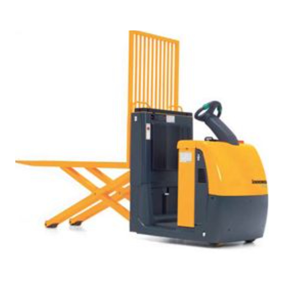
B Truck Description Application The ECE 220/225 is a four-wheel electric pallet truck with an operator position, equipped either with a Jet Pilot or electric tiller steering (o). The truck is designed to transport and pick goods on level surfaces. Roll cages and open bottom pallets or pallets with transverse boards (provided these are outside the range of the load wheels) can be collected. -
Page 11: Assemblies
Assemblies Item Model Item Model t Front panel o “Lift” button t Battery panel o “Lower” button t Jet Pilot o Reverse “pedestrian operation” button t Main switch / isolator t Forward “pedestrian (emergency disconnect) operation” button t Controller t Operator platform t Brake button t Lift mechanism o Keypad... -
Page 12: Standard Version Specifications
Standard Version Specifications Technical specification details in accordance with VDI 2198. Technical modifications and additions reserved. Performance Data Model ECE 320 Q Rated capacity 2000 Load centre distance with 1200 standard fork length * Travel speed 9.5 / 12.5 km/h w / w.o. -
Page 13: Dimensions
Dimensions (all dimensions in mm) Model ECE 320 Overall length 3750 Headlength 1350 Lowered fork height Rated lift Mast height retracted 1505 Battery panel height Operator platform height Truck width Track Width 2400 Inside spread Fork length Width across forks... -
Page 14: En Norms
EN norms Noise level: 61 dB(A) in accordance with EN 12053 as harmonized with ISO 4871. The noise emission level is calculated in accordance with standard procedures and takes into account the noise level when travelling, lifting and when idle. The noise level is measured at the driver’s ear. -
Page 15: Identification Points And Data Plates
Identification points and data plates 2000 Item Model “Attention Touch Mode” warning decal *) for “Touch mode only in drive direction” option Test sticker (o) Truck data plate Warning: “Do not reach into the mast” Serial number, on the left or right of the mast section Attachment point of crane loading (inside), hook symbol enhanced Capacity Qmax The capacity plate (26) indicates the maximum capacity of the truck, Qmax. - Page 16 Truck data plate Item Model Item Model Type Manufacturer Serial no. Min./max. battery weight (kg) Rated capacity (kg) Output (kW) Battery: Voltage (V) Load centre of gravity (mm) Net weight w.o. battery (kg) Year of Manufacture Manufacturer’s logo Option For queries relating to the truck or spare part orders, please state the truck’s serial no.
-
Page 18: C Transport And Commissioning
C Transport and Commissioning Lifting by crane Only lifting gear with sufficient capacity (for transport weight see truck data plate). Lifting gear attachment points are provided on the chassis (1) and the fork (2) in case the truck is to be lifted or transported by crane. -
Page 19: Securing The Truck During Transport
Securing the truck during transport The truck must be securely fastened when transported on a lorry or a trailer. The lorry / trailer must have fastening rings. – To secure the truck attach the tensioning belt to the strap points (1) and secure them to the fastening rings. -
Page 20: Using The Truck For The First Time
Using the truck for the first time Only operate the truck with battery current. Rectified AC current will damage the electronic components. Cables connected to the battery (trailing cables) must be less than 6 meters in length. To prepare the truck after delivery or after transport, proceed as follows: –... -
Page 21: Operating The Truck Without Its Own Drive System
Operating the truck without its own drive system This operating mode is not permitted when negotiating inclines and gradients. If the truck has to be moved after a failure has rendered it immobile, proceed as follows: – Set the isolator “OFF”. –... -
Page 22: D Battery Maintenance, Charging & Replacement
D Battery Maintenance, Charging & Replacement Safety regulations for handling acid batteries Park the truck securely before carrying out any work on the batteries (see Chapter E). Maintenance personnel: Batteries may only be charged, serviced or replaced by trained personnel. The present operator manual and the manufacturer’s instructions concerning batteries and charging stations must be observed when carrying out the work. -
Page 23: Battery Types
Battery types The truck will be equipped with different battery types, depending on the application. The following table shows which combinations can be included as standard: 24 V PzS battery 3 PzS 420 Ah L 24 V - PzS battery 3 PzS 450 Ah HX high performance The battery weights can be taken from the battery data plate. -
Page 24: Charging The Battery
Charging the battery To charge the battery, the truck must be parked in a closed and properly ventilated room. – Expose the battery (see Section 3). The battery connector (4) and the charging cable (6) of the battery charging station must only be connected or disconnected when the truck and the battery charger are switched off. -
Page 25: Battery Removal And Installation
Battery removal and installation The truck must be parked on level ground. To prevent short circuits, batteries with exposed terminals or connectors must be covered with a rubber mat. Place the battery connector or the battery cable in such a way that they will not get caught on the truck when the battery is withdrawn. -
Page 26: E Operation
E Operation Safety Regulations for the Operation of Forklift Trucks Driver authorisation: The forklift truck may only be used by suitably trained personnel, who have demonstrated to the proprietor or his representative that they can drive and handle loads and have been authorised to operate the truck by the proprietor or his representative. -
Page 27: Controls And Displays
Controls and Displays Item Control / Display Function t The circuit is interrupted, all electrical 1 Main switch / isolator (emergency disconnect) functions are cut out and the truck automatically brakes. t Triggers a warning signal. 2 “Horn” button t Lowers the lift mechanism. 3 “Lower”... - Page 28 11 12 13...
-
Page 29: Ism (O)
Item Control / Display Function o Replaces the key switch. 11 Code Lock Switches control voltage on and off. Activates the truck functions. o Switch current on and off. CANCODE keypad Code settings. Release and select the travel programs. Enter travel parameters. o Code settings. - Page 30 11 12 13...
-
Page 31: Starting Up The Truck
Starting up the truck Before the truck can be started, operated or a load lifted, the driver must ensure that there is nobody within the hazardous area. The electronic traction controller and the steering controller monitor their own operation. In the event of an error, travel and steering are interrupted. The error must be rectified by the manufacturer's service department. -
Page 32: Industrial Truck Operation
Industrial Truck Operation Safety regulations for truck operation Travel routes and work areas: Only use lanes and routes specifically designated for truck traffic. Unauthorised third parties must stay away from work areas. Loads must only be stored in places specially designated for this purpose. Driving conduct: The driver must adapt the travel speed to local conditions. -
Page 33: Travel, Steering, Braking
Travel, steering, braking Be extremely careful when driving and steering, especially when operating outside the geometry of the truck. The electric steering system is self-monitoring. The steering controller monitors the fault frequency over a certain period. If the same fault is detected several times during this period, the steering controller reduces the travel speed of the truck to slow travel. - Page 34 Travel Do not drive the truck unless the panels are closed and properly locked. – Start up the truck (refer to section 3). – Set the controller (6) to the desired travel direction: forward (V) or reverse (R). The truck starts to travel in the direction selected. The travel speed is governed by the controller (6).
- Page 35 Travelling on inclines Loads must always be carried on the end of the truck facing uphill. Preventing the truck from rolling back: With the controller (6) set to neutral, the service brake automatically applies after a short jerk (the controller detects downhill motion on an incline). The service brake is released again via the controller (6), which is also used to select the speed and the travel direction.
- Page 36 Braking The brake pattern of the truck depends largely on the ground conditions. The driver must take this into account when operating the truck. The truck can brake in three different ways: – with the service brake – by regenerative braking (coasting) –...
-
Page 37: Pedestrian Operation (O)
Pedestrian operation (o) When travelling in pedestrian mode you must make sure – while walking alongside – that the steering system is set to straight ahead travel and that the operator cannot be trapped between the truck and an obstacle. In pedestrian mode the truck can be operated by the operator from all sides while walking alongside. - Page 38 Travel using the controller – Set the controller (6) to the desired travel direction: forward (V) or reverse (R). The truck moves at reduced speed (can be set up to a maximum of 4 km/h). Travel using the “pedestrian” button –...
-
Page 39: Lifting And Depositing Loads
Lifting and depositing loads Before raising a load, the driver must ensure that it is correctly palletised and that the capacity of the truck is not exceeded. – Enter the truck and the lift unit as far as possible underneath the load. Do not lift long loads at an angle. -
Page 40: Parking The Truck Securely
Parking the truck securely When you leave the truck it must be securely parked even if you only intend to leave it for a short time. Do not park the truck on a slope. The lift mechanism must always be completely lowered. -
Page 41: Keypad (Cancode) (O)
Keypad (CANCODE) (o) The keypad consists of 10 digit keys, a Set key and a o key. Activation of the travel programs is indicated through green LEDs on keys 1, 2 and 3. The o key indicates operational status through a red/green LED. - Page 42 Commissioning When the main switch is turned on the LED (21) goes red. When you enter the correct operator code (factory setting 2-5-8-0) the LED (21) turns green. If the wrong code is entered LED (21) flashes red for two seconds. The correct code can then be entered.
-
Page 43: Travel Programs
Travel programs Press the digit keys 1, 2, and 3 to select any of three travel programs. The activated program is indicated by the green LEDs (23), (24), (25) in the corresponding key. The travel programmes differ with respect to travelling speed, acceleration, and deceleration. -
Page 44: Parameter Settings
Parameter Settings To change the truck setting you must enter the master code. The factory setting for the master code is 7-2-9-5. When starting the truck for the first time, change the master code (see section 5.1). Safety notes for trucks with indicator instrument (CANDIS (o)) –... - Page 45 Setting procedure for trucks with and without display instrument (CANDIS (o)): – Enter the three digit parameter number, confirm with the Set key (22). – The display instrument (CANDIS (o)) continues to display the operating hours. If the display changes, cancel the setting procedure with the o key (26) and restart from the beginning.
- Page 46 Function Setting Standard Comments range setting Procedure Code Lock 002 Change user code 0000 - 9999 (LED 23 flashes) Enter current code 00000 - 99999 Confirm (Set) 000000 - 999999 (LED 24 flashes) Enter a new code Confirm (Set) (LED 25 flashes) Repeat code entry Confirm...
- Page 47 Start Travel Program Setting with Code Lock Function Setting Standard Comments range setting Procedure Code Lock 024 User code 1112 configuration The travel programs are connected to the user code. The travel programs can be individually released or blocked for each user code. A start travel program can be assigned to each user code.
-
Page 48: Travel Parameters
Travel parameters For trucks without a display instrument (CANDIS (o)) the code lock parameters can only be set by the manufacturer's service department. The following example shows the parameter setting for the acceleration of travel program 1 (parameter 101). Acceleration example Enter the three digit parameter number (101) and confirm with the Set key (22). - Page 49 Travel is disabled while the parameters are being entered. If the setting is to be checked in programming mode, follow this sequence: – Select the edited travel program after changing the parameter value, confirm with the Set key (22). – The truck is now in travel mode and can be checked. –...
- Page 50 Function Setting Standard Comments range setting Travel program 2 200 Acceleration in 0 - 9 Value of parameter 201 >= Parameter Pedestrian mode 201 Acceleration in 0 - 9 Rider mode 202 Coasting brake in 0 - 9 rider mode 203 Coasting brake in 0 - 9 Value of parameter...
- Page 51 Function Setting Standard Comments range setting Travel program 3 300 Acceleration in 0 - 9 Value of parameter 301 >= Parameter Pedestrian mode 301 Acceleration in 0 - 9 Rider mode 302 Coasting brake in 0 - 9 rider mode 303 Coasting brake in 0 - 9 Value of parameter...
- Page 52 Program-independent parameters For trucks without a display instrument (CANDIS (o)) the parameters can BATTERY only be set by the manufacturer's service department. The parameters are set in the same way as for the travel parameters. The following parameters may be entered. Function Setting Standard...
-
Page 53: Battery Discharge Indicator (T)
Battery discharge indicator Battery Discharge Indicator (t) When the truck has been released via the key switch or CANCODE, the battery charge status is displayed. The colours of the LEDs (12) represent the following conditions: LED colour Meaning Green Battery is charged Orange Battery residual capacity approx. -
Page 54: Display Instrument (Candis) (O)
Display instrument (CANDIS) (o) The instrument indicates: 27 Attention pre-warning symbol, battery charge required 28 Capacity display bars Battery residual charge status 29 Stop symbol; lift cutout, battery charge required 30 6 digit LCD display; hourmeter; entry display; error display 31 T symbol appears during operation when the discharge indicator is set to maintenance-free battery... -
Page 55: Operating Hours Display
Operating hours display Hourmeter: The hourmeter (30) contained in the battery discharge indicator shows the overall travel and lifting times. The meter starts as soon as the operator stands on the operator platform or uses pedestrian mode. Display range between 0.0 and 99,999.0 hours. Travel and lifting are logged. This is a backlit display. -
Page 56: Troubleshooting
Troubleshooting This chapter is designed to help the user identify and rectify basic faults or the results of incorrect operation. When locating a fault, proceed in the order shown in the table. Fault Probable Cause Action Truck – Battery connector –... - Page 57 E 32...
-
Page 58: F Industrial Truck Maintenance
F Industrial Truck Maintenance Operational Safety and Environmental Protection The checks and servicing operations contained in this chapter must be performed in accordance with the intervals as indicated in the servicing checklists. Any modification to the forklift truck assemblies, in particular the safety mechanisms, is prohibited. - Page 59 Electrical System: Only suitably trained personnel may operate on the truck’s electrical system. Before working on the electrical system, take all precautionary measures to avoid electric shocks. For battery-operated trucks, also de-energise the truck by removing the battery connector. Welding: To avoid damaging electric or electronic components, remove these from the truck before performing welding operations.
-
Page 60: Servicing And Inspection
The application conditions of an industrial truck have a considerable impact on the wear of the service components. We recommend that a Jungheinrich customer service adviser carries out an application analysis on site to work out specific service intervals to prevent damage due to wear. -
Page 61: Maintenance Checklist
Maintenance checklist Maintenance Intervals = t W A B C Standard Cold store Brake 1.1 Check magnetic brake air gap Electrics 2.1 Test of instruments, displays and control switches 2.2 Test warning and safety device. 2.3 Check fuse ratings. 2.4 Make sure wire connections are secure and check for damage. - Page 62 Maintenance Intervals = t W A B C Standard Cold store Hydraulic 6.1 Visually inspect rollers, slide pieces and stops. operation 6.2 Test operation of lift mechanism, check for wear and check settings. 6.3 Test hydraulic system. 6.4 Check that hose and pipe lines and their connections are secure, check for leaks and damage, and tighten unions if necessary.
-
Page 63: Lubrication Schedule
Lubrication Schedule A + C 1,05 l 0,7 l Contact surfaces Grease nipple Gear oil filler neck Gear oil drain plug Cold store application 1) Cold store mix ratio 1:1 2) Transmission oil values are guidelines only. The spur wheel should be dipped approx. -
Page 64: Consumables
Consumables Handling consumables: Consumables must always be handled correctly. Follow the manufacturer’s instructions. Improper handling is hazardous to health, life and the environment. Consumables must only be stored in appropriate containers. They may be flammable and must therefore not come into contact with hot components or naked flames. Only use clean containers when filling up with consumables. -
Page 65: Maintenance Instructions
Maintenance Instructions Preparing the truck for maintenance and repairs All necessary safety measures must be taken to avoid accidents when carrying out maintenance and repairs. The following preparations must be made: – Park the truck securely (see Chapter E). – Disconnect the battery so that the truck cannot be started by unauthorised persons (see chapter D). -
Page 66: Remove The Front Panel
Remove the front panel – Open battery panel (see chapter D). – Remove the screws (5). – Lift up the front panel (4) and put it to one side. Installation is the reverse order. Do not drive the truck unless the panels are closed and properly locked. -
Page 67: Checking Electrical Fuses
Checking electrical fuses – Prepare the truck for maintenance and repairs (see Chapter 6.1). – Remove the front panel (see Section 6.3). – Referring to the table, check all fuses for correct rating and damage; replace fuses where required. 6 7 8 9 Item Model To protect:... -
Page 68: Recommissioning
Recommissioning The truck may only be restored to service after cleaning or repair work, once the following operations have been performed. – Test horn. – Test main switch operation. – Test brakes. – Lubricate the truck in accordance with the lubrication schedule. Decommissioning the industrial truck If the industrial truck is to be decommissioned for more than two months, e.g. -
Page 69: Returning The Truck To Operation After Decommissioning
Carry out a safety check in accordance with national regulations. Junheinrich recommends checks in accordance with FEM Guideline 4.004. Jungheinrich has a special safety department with trained personnel to carry out such checks. The truck must be inspected at least annually (refer to national regulations) or after any unusual event by a qualified inspector. - Page 70 Jungheinrich traction battery Table of contents Jungheinrich traction battery ..........2-6 with positive tubular plates type EPzS and EPzB Type plate Jungheinrich traction battery..........7 Instruction for use ............8-12 Aquamatic/BFS III water refilling system Jungheinrich traction battery Maintenance free traction batteries with positive tubular plates type EPzV ....................13-17...
- Page 71 Jungheinrich traction battery with positive tubular plates type EPzS and EPzB Rating Data 1. Nominal capacity C5: See type plate 2. Nominal voltage: 2,0 V x No of cells 3. Discharge current:: C5/5h 4. Nominal S.G. of electrolyte* Type EPzS:...
- Page 72 Ignoring the operation instructions, repair with non-original parts or using additives for the electrolyte will render the warranty void. For batteries in classes I and II the instructions for maintaining the appropriate protection class during operation must be complied with (see relevant certificate). 1.
- Page 73 Battery container lids and the covers of battery compartments must be opened or re- moved. The vent plugs should stay on the cells and remain closed. With the charger switched off connect up the battery, ensuring that the polarity is cor- rect.
- Page 74 3. Maintenance 3.1 Daily Charge the battery after every discharge. Towards the end of charge the electrolyte level should be checked and if necessary topped up to the specified level with purified water. The electrolyte level must not fall below the anti-surge baffle or the top of the separator or the electrolyte „min“...
- Page 75 5. Storage If batteries are taken out of service for a lengthy period they should be stored in the fully charged condition in a dry, frost-free room. To ensure the battery is always ready for use a choice of charging methods can be made: 1.
- Page 76 7. Type plate, Jungheinrich traction battery Baujahr T ype Year of manufacture Serien-Nr. Lieferanten Nr. Serial-Nr. Supplier No. Nennspannung Kapazität Nominal V oltage Capacity Zellenzahl Batteriegewicht min/max Number of Cells Battery mass min/max Hersteller Jungheinrich AG, D-22047 Hamburg, Germany Manufacturer...
- Page 77 Aquamatic/BFS III water refilling system for Jungheinrich traction battery with EPzS and EPzB cells with tubular positive plates Aquamatic plug arrangement for the Operating Instructions Cell series* Aquamatic plug type (length) EPzS EPzB Frötek (yellow) (black) 2/120 – 10/ 600 2/ 42 –...
- Page 78 Diagrammatic view Equipment for the water refilling system 1. Water tank 2. Level switch 3. Discharge point with ball valve 4. Discharge point with sole- noid valve 5. Charger 6. Sealing coupler 7. Closing nipple 8. Ion exchange cartridge with conductance meter and solenoid valve 9.
- Page 79 4. Filling (manual/automatic) The batteries should be filled with battery water as soon as possible before the battery charging comes to an end; this ensures that the refilled water quantity is mixed with the electrolyte. In normal operation it is usually sufficient to fill once a week. 5.
- Page 80 8. Battery hose connections Hose connections for the individual plugs are laid along the existing electric circuit. No changes may be made. 9. Operating temperature The temperature limit for battery operation is set at 55° C. Exceeding this temperature damages the batteries. The battery filling systems may be operated within a tempe- rature range of >...
- Page 81 10.2.1 Clamping ring tool The clamping ring tool is used to push on a clamping ring to increase the contact pres- sure of the hose connection on the plugs' hose couplings and to loosen it again. 10.3 Filter element For safety reasons a filter element (ident no.: 50307282) can be fitted into the batte- ry's main supply pipe for supplying battery water.
- Page 82 Jungheinrich traction batterie Maintenance free Jungheinrich traction batterie with positive tubular plates type EPzV and EPzV-BS Rating Data 1. Nominal capacity C5: See type plate 2. Nominal voltage: 2,0 Volt x No of cells 3. Discharge current: C5/5h 4. Rated temperature: 30°...
- Page 83 Ignoring the operation instructions, repair with non-original parts and non authorised interventions will render the warranty void. For batteries in classes I and II the instructions for maintaining the appropriate protection class during operation must be complied with (see relevant certificate). 1.
- Page 84 With the charger switched off connect up the battery, ensuring that the polarity is cor- rect (positive to positive, negative to negative). Now switch on the charger. When charging the temperature of the battery rises by about 15° C, so charging should only begin if the battery temperature is below 35°...
- Page 85 3.2 Weekly Visual inspection after recharging for signs of dirt and mechanical damage. 3.3 Quarterly After the end of the charge and a rest time of 5 h following should be measured and recorded: • the voltages of the battery •...
- Page 86 Batteries with this sign must be recycled. Batteries which are not returned for the recycling process must be disposed of as hazardous waste! We reserve the right make technical modification. 7. Type plate, Jungheinrich traction battery Baujahr T ype Year of manufacture Serien-Nr.
Need help?
Do you have a question about the ECE 320 and is the answer not in the manual?
Questions and answers