Table of Contents
Advertisement
Quick Links
Advertisement
Table of Contents

Related Manuals for Jungheinrich ESE 420


Summary of Contents for Jungheinrich ESE 420
- Page 1 ESE 420/430 11.04 - Operating Instructions 50454697 11.08...
- Page 2 Used to indicate standard equipment. Used to indicate optional equipment. Our trucks are subject to ongoing development. Jungheinrich reserves the right to alter the design, equipment and technical features of the truck. No guarantee of particular features of the truck should therefore be inferred from the present operating instructions.
-
Page 4: Table Of Contents
Index Correct use and application Truck Description Application ................... B 1 Assemblies and Functional Description ..........B 2 Truck ....................B 3 Standard Version Specifications ............B 5 Performance data ................B 5 Dimensions ..................B 6 EN norms .................... B 7 Conditions of use ................ - Page 5 Operational safety and environmental protection ........ F 1 Maintenance Safety Regulations ............F 1 Servicing and inspection ..............F 3 ESE 420/430 Maintenance Checklist ..........F 4 ESE 420/430 Lubrication Schedule ............ F 6 Fuels, coolants and lubricants ............. F 7 Maintenance Instructions ..............
- Page 6 Appendix JH Traction Battery Operating Instructions These operating instructions apply only to Jungheinrich battery models. If using another brand, refer to the manufacturer's operating instructions.
-
Page 8: A Correct Use And Application
A Correct use and application The “Guidelines for the Correct Use and Application of Industrial Trucks” (VDMA) are supplied with the truck. The guidelines form part of these operating instructions and must be observed. National regulations apply in full. The truck described in the present operator manual is an industrial truck designed for lifting and transporting load units. -
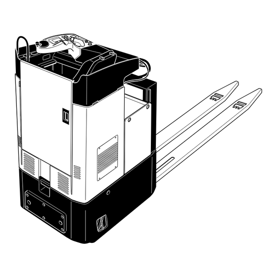
Page 10: B Truck Description
Maximum emphasis has been placed on the ergonomic design of the operator position and work safety. The controls are intuitively and clearly arranged and are adapted to the task of transporting. Truck types and capacity: Type Capacity ESE 420 2000kg ESE 430 3000kg... -
Page 11: Assemblies And Functional Description
Assemblies and Functional Description Item Description Item Description t Driver’s display t Accelerator pedal t Hydraulic control button t Driver's seat t Parking brake t Lift mechanism t Key switch t Drive wheels t Main switch / isolator t Castor wheel (emergency disconnect) o Driver door o Emergency steering mode... -
Page 12: Truck
Truck Safety mechanisms: Enclosed, smooth truck geometry. The wheels (12/13) are surrounded by a solid ram protection skirting. This protects the load in the event of a collision. The key switch (4) or isolator (emergency disconnect) (5) disconnects all electrical function in hazardous situations. Travelling is inhibited if the driver door is not closed. - Page 13 Emergency Stop Safety Feature: The emergency stop is governed by the brake controller. The steering controller transmits a system status signal which is monitored by the brake controller. If the signal fails to appear or a fault is identified the truck automatically brakes until it comes to rest.
-
Page 14: Standard Version Specifications
Standard Version Specifications Technical data specified in accordance with VDI 2198. Technical modifications and additions reserved. Performance data Description ESE 420 ESE 430 Q Rated capacity 2000 3000 Load centre distance 1200 1200 with standard fork length * 14.0/14.0 14.0/14.0... -
Page 15: Dimensions
Dimensions (all dimensions in mm) Description ESE 420 ESE 430 Lift Seat height 1200 1200 Lowered fork height Overall length 4825 4825 Headlength 1225 1225 Truck width 1000 1000 Width across forks 520/560 Track width, drive Track width, load section... -
Page 16: Norms
EN norms Noise emission: 68 dB(A) in accordance with EN 12053 as harmonised with ISO 4871. The noise emission level is calculated in accordance with standard procedures and takes into account the noise level when travelling, lifting and when idle. The noise level is measured at the driver’s ear. -
Page 17: Technical Description - Load Handler
Technical Description – Load Handler Lift mechanism: The lift mechanism (11) and load fork is connected to the chassis via the lift cylinder and the lift linkage. The load forks are raised when the lift cylinder is extended while simultaneously moving the load wheel support through the lift linkage. - Page 18 Truck data plate Item Description Item Description Type Manufacturer’s logo Serial no. Min./max. battery weight (kg) Rated capacity (kg) Output (kW) Battery voltage (V) Load centre of gravity (mm) Net weight excl. battery Year of manufacture Manufacturer Option For queries regarding the truck or ordering spare parts please quote the truck serial number (21).
- Page 19 B 10...
-
Page 20: C Transport And Commissioning
C Transport and Commissioning Lifting by crane Only use lifting gear with sufficient capacity (for transport weight see truck data plate). – Remove the dummy plugs from the load section and screw in the two ring screws (1). – If loading the truck with crane lifting gear, attach the load hooks to the ring screws (1) on either side and also to the lift mechanism (2). -
Page 21: Parking Brake Transport Lock
Parking brake transport lock If a truck is supplied without a battery or with an uncharged battery, the transport lock (2xM5) must be removed before starting to use the truck. The transport lock is used to lock the compression spring which activates the parking brake, so that the truck is not braked when de-energised. -
Page 22: Commissioning
Moving the truck without a battery – Disconnect the battery. – Push the driver’s seat out of the guide towards the steering wheel. – Disconnect the fan connector on the seat panel. – Remove seat panel (see Chapter F). – Disconnect the two-pin connector from the magnetic brake. –... -
Page 24: D Battery Maintenance, Charging & Replacement
D Battery Maintenance, Charging & Replacement Safety regulations for handling acid batteries Park the truck securely before carrying out any work on the batteries (see Chapter E). Maintenance personnel: Batteries may only be charged, serviced or replaced by trained personnel. The present operator manual and the manufacturer’s instructions concerning batteries and charging stations must be observed when carrying out the work. -
Page 25: Battery Types
Battery types The truck will be equipped with different battery types, depending on the application. The following table shows which combinations can be included as standard: 48V - PzS battery, low maintenance 560 Ah 48V - PzS battery, maintenance-free 560 Ah The battery weights can be taken from the battery data plate. -
Page 26: Charging The Battery
Charging the battery – Park the truck securely (see Chapter E). When charging the low maintenance battery, the tops of the battery cells must be exposed to provide sufficient ventilation. This is not necessary for maintenance-free batteries. Do not place any metal objects on the battery. Before charging, check all cables and plug connections for visible signs of damage. -
Page 27: Battery Removal And Installation
Battery removal and installation – Expose the battery (see Section 3). To prevent short circuits, batteries with exposed terminals or connectors must be covered with a rubber mat. When replacing a battery with a crane, make sure the crane has sufficient capacity (see battery weight on the battery data plate on the container). -
Page 28: Driver's Display
Driver’s display Battery Discharge Indicator: The battery charge status of the battery (7) is shown on the driver’s display. The standard setting for the battery discharge indicator / discharge monitor is based on standard batteries. When a battery is discharged to the permissible discharge level, the battery symbol is displayed empty. -
Page 30: Safety Regulations For The Operation Of Forklift Trucks
E Operation Safety Regulations for the Operation of Forklift Trucks Driver authorisation: The forklift truck may only be used by suitably trained personnel, who have demonstrated to the proprietor or his representative that they can drive and handle loads and have been authorised to operate the truck by the proprietor or his representative. -
Page 31: Controls And Displays
Controls and Displays Item Control /Display Function t Steers truck in desired direction. Steering wheel t Displays key travel and lift parameters, Driver’s display warnings, notification of incorrect operation and service displays (see Section 5). o Switches driver seat heating on and off. Switch for driver seat heating t When lit, indicates that the maximum travel... - Page 32 17 18...
-
Page 33: Starting Up The Truck
Starting up the truck Before the truck can be commissioned, operated or a load unit lifted, the driver must ensure that there is nobody within the hazardous area. Checks and operations to be performed before starting daily work – The entire truck (in particular wheels and load lifting devices) must be inspected for damage. - Page 34 Attaching the safety restraint belt The safety belt (21) must be worn at all times when travelling. The belt must audibly lock in place when closed. Place the safety belt (21) taught over your hips (not over fixed or fragile objects in the pockets of your clothes). The safety belt (21) should be as close as possible to your hips.
-
Page 35: Emergency Stop Device
Emergency stop device The truck is fitted with an emergency stop device. After you switch on the isolator (11) and the key switch (10) there is an automatic safety prompt from the steering controller. Emergency stop activation If a fault occurs in the steering system while travelling which affects the safety of the operator, the truck will brake in a controlled manner until it comes to a halt. -
Page 36: Industrial Truck Operation
Industrial Truck Operation Safety regulations for truck operation Travel routes and work areas: Only use lanes and routes specifically designated for truck traffic. Unauthorised persons must stay away from work areas. Loads must only be stored in places specially designated for this purpose. Driving conduct: The driver must adapt the travel speed to local conditions. -
Page 37: Travel, Steering, Braking
Travel, Steering, Braking Emergency stop – Press the isolator (11) down. All electrical functions are deactivated. Door contact switch The door contact switch must be applied (door closed) for all operating functions. If the door contact switch is not applied, all functions, except for the battery discharge indicator, are deactivated. - Page 38 Braking The braking pattern of the truck depends largely on the state of the ground. The driver must take this into account when operating the truck. The truck can be braked in two different ways: – using the service brake –...
-
Page 39: Collecting And Depositing Loads
Collecting and depositing loads Before picking up a load, the driver must ensure that it is correctly palletised and that the capacity of the truck is not exceeded. – Drive the truck with forks as far as possible underneath the load. Lift –... -
Page 40: Truck Recovery In The Event Of Electric Steering Failure
Truck recovery in the event of electric steering failure Recovery must only be undertaken by maintenance personnel who have been trained to operate the system. – Turn the EMERGENCY DISCON- NECT switch and key switch off. – Prevent the truck from rolling away. –... -
Page 41: Display Components
Display Components Driver’s display (t) The driver’s display represents the operator interface to the truck. It is both a display and control unit for the operator and the service engineer. Press the four short stroke keys (37, 38, 39, 40) to operate the driver's display and hence the truck. - Page 42 Item Description Overtemperature (red graphic symbol) Deadman button not applied (yellow graphic symbol) Slow travel (green graphic symbol) Service mode active (yellow spanner graphic symbol) Service interval exceeded (flashing graphic symbol) Steering angle display in 30° increments in arrow form Travel direction display No function Time display (hours : minutes...
- Page 43 You can use the four short stroke keys to: – derate the travel speed (slow travel switch), – change the display to service mode (shift key) and – select travel and lift modes. The display shows: – The steering angle in 30° increments in arrow form. –...
-
Page 44: Driver's Display Led Buttons
Driver’s Display LED Buttons SYMBOL Slow travel (green graphic symbol) SYMBOL Deadman button not applied (yellow graphic symbol) SYMBOL Service mode active (yellow spanner graphic symbol) SYMBOL Overtemperature (red graphic symbol) Driver’s Display Switches Travel speed derated (slow travel switch), Handbrake applied / release (brake switch) Change display to service mode (shift key) Select travel and lift modes... - Page 45 Driver’s Display Warning Messages 29 30 31 32 Display Other action Meaning LED 31 flashing Battery empty, main lift cutout LED 24 on Safety switch not pressed At least 1 control not in home position when system INFO 07 LED 25 flashing starts INFO 09 LED 25 on Crawl speed applied or forced by battery latching...
-
Page 46: Keypad (Cancode) (O)
Keypad (CANCODE) (o) The keypad consists of 10 number keys, a Set key and a o key. The o key indicates operating statuses via a red/ green LED. It contains the following functions: – Code lock function (starting up the truck). Code Lock When the correct code has been entered, the machine is ready for use. -
Page 47: Parameters
Starting the truck for the first time After switching on the isolator and if necessary the key switch, the LED (41) turns red. When you enter the correct operator code the LED (41) turns green. If the wrong code is entered LED (41) flashes red for two seconds. The correct code can then be entered. -
Page 48: Parameter Settings
Parameter Settings To change the truck setting you must enter the master code. The factory setting for the master code is 7-2-9-5. When starting the truck for the first time change the master code. To enter the master code: – Press the o key –... - Page 49 The following parameters may be entered. Code Lock Parameter List Comments Range of Standard Function Setting Setting Procedure Code Lock 000 Change Master Code 0000 - 9999 7295 (LED 43 flashes) Enter The length (4-6 digits) of current code the master code also pre- 00000 - 99999 determines the length of the operator code (4-6...
- Page 50 Comments Range of Standard Function Setting Setting Procedure Code Lock 002 Change Operator Code 0000 - 9999 (LED 43 flashes) Enter current code 00000 - 99999 Confirm (Set) 000000 - 999999 (LED 44 flashes) Enter new code Confirm (Set) (LED 45 flashes) Repeat code entry confirm...
-
Page 51: Changing Truck Parameters
Error messages on keypad LED (41) flashes red to indicate the following errors: – New master code is already an operator code. – New operator code is already a master code. – Operator code to be changed does not exist. –... -
Page 52: Troubleshooting
Troubleshooting This chapter is designed to help the user identify and rectify basic faults or the results of incorrect operation. When locating a fault, proceed in the order shown in the table. Fault Possible cause Action Truck does not – Battery not connected. –... - Page 53 E 24...
-
Page 54: F Forklift Truck Maintenance
F Forklift Truck Maintenance Operational safety and environmental protection The servicing and inspection operations contained in this chapter must be performed in accordance with the intervals indicated in the servicing checklists. Any modification to the forklift truck assemblies, in particular the safety mechanisms, is prohibited. - Page 55 Electrical System: Only suitably trained personnel may operate on the truck’s electrical system. Before working on the electrical system, take all precautionary measures to avoid electric shocks. For battery-operated trucks, also de-energise the truck by removing the battery connector. Welding: To avoid damaging electric or electronic components, remove these from the truck before performing welding operations.
-
Page 56: Servicing And Inspection
Servicing and inspection Thorough and expert servicing is one of the most important requirements for the safe operation of the industrial truck. Failure to perform regular servicing can lead to truck failure and poses a potential hazard to personnel and equipment. The service intervals stated are based on single shift operation under normal operating conditions. -
Page 57: Ese 420/430 Maintenance Checklist
ESE 420/430 Maintenance Checklist Maintenance intervals = t W A B C Standard Cold Store Chassis/ 1.1 Check all load bearing components for damage Structure: 1.2 Check screw connections Drive: 2.1 Check the transmission for noises and leakage 2.2 Check transmission oil level 2.3 Change transmission oil... - Page 58 Maintenance intervals = t W A B C Standard Cold Store Electrical 7.1 Test operation System: 7.2 Make sure wire connections are secure and check for damage 7.3 Check fuse ratings 7.4 Test operation of switches and trip cams and make sure they are secure 7.5 Test operation of warning devices and safety switches 7.6 Check contactors, replace any worn parts...
-
Page 59: Ese 420/430 Lubrication Schedule
ESE 420/430 Lubrication Schedule D 0,2 l A + C 0,7 l 2,9 l 195 -10 Nm Contact surfaces Grease nipples Hydraulic oil filler plug Transmission oil filler neck Transmission oil drain plug Cold store application Brake fluid filler neck... -
Page 60: Fuels, Coolants And Lubricants
Fuels, coolants and lubricants Handling consumables: Consumables must always be handled correctly. Follow the manufacturer’s instructions. Improper handling is hazardous to health, life and the environment. Consumables must only be stored in appropriate containers. They may be flammable and must therefore not come into contact with hot components or naked flames. -
Page 61: Maintenance Instructions
Maintenance Instructions Preparing the truck for maintenance and repairs All necessary safety measures must be taken to avoid accidents when carrying out maintenance and repairs. The following preparations must be made: – Park the truck securely (see Chapter E). – Disconnect the battery plug so that the truck cannot be started by unauthorised persons (see chapter D). -
Page 62: Lift Up The Door Attachment
Lift up the door attachment – if necessary open the truck door (1). – Push the driver’s seat to the furthest stop at the front. – Loosen and unscrew the hex. socket screws (2). – Lift up the door attachment (3). The battery is accessible for servicing. -
Page 63: Checking Electrical Fuses
Checking electrical fuses – Prepare the truck for maintenance and repairs (see Section 6.1). – Open the steering controller (see Section 6.4). – Check rating of all fuses in accordance with table, replace if necessary. Item Description To protect: Rating Vacant Measurement Discharge indicator/ hourmeter... -
Page 64: Recommissioning
Recommissioning The truck may only be recommissioned after cleaning or repair work, once the following operations have been performed. – Test horn. – Test main switch operation. – Test brake. – Lubricate the truck in accordance with the lubrication schedule. Decommissioning the industrial truck If the industrial truck is to be decommissioned for more than two months, e.g. -
Page 65: Restoring The Truck To Operation After Decommissioning
Restoring the truck to operation after decommissioning – Thoroughly clean the truck. – Lubricate the truck in accordance with the lubrication schedule (see chapter F). – Clean the battery, grease the terminals and connect the battery. – Charge the battery (see Chapter D). –... -
Page 66: Safety Checks To Be Performed At Regular Intervals And Following Any Unusual Incidents
Carry out a safety check in accordance with national regulations. Junheinrich recommends checks in accordance with FEM Guideline 4.004. Jungheinrich has a special safety department with trained personnel to carry out such checks. The truck must be inspected at least annually (refer to national regulations) or after any unusual event by a qualified inspector. - Page 68 Jungheinrich traction battery Table of contents Jungheinrich traction battery ..........2-6 with positive tubular plates type EPzS and EPzB Type plate Jungheinrich traction battery..........7 Instruction for use ............8-12 Aquamatic/BFS III water refilling system Jungheinrich traction battery Maintenance free traction batteries with positive tubular plates type EPzV ....................13-17...
- Page 69 Jungheinrich traction battery with positive tubular plates type EPzS and EPzB Rating Data 1. Nominal capacity C5: See type plate 2. Nominal voltage: 2,0 V x No of cells 3. Discharge current:: C5/5h 4. Nominal S.G. of electrolyte* Type EPzS:...
- Page 70 Ignoring the operation instructions, repair with non-original parts or using additives for the electrolyte will render the warranty void. For batteries in classes I and II the instructions for maintaining the appropriate protection class during operation must be complied with (see relevant certificate). 1.
- Page 71 Battery container lids and the covers of battery compartments must be opened or re- moved. The vent plugs should stay on the cells and remain closed. With the charger switched off connect up the battery, ensuring that the polarity is cor- rect.
- Page 72 3. Maintenance 3.1 Daily Charge the battery after every discharge. Towards the end of charge the electrolyte level should be checked and if necessary topped up to the specified level with purified water. The electrolyte level must not fall below the anti-surge baffle or the top of the separator or the electrolyte „min“...
- Page 73 5. Storage If batteries are taken out of service for a lengthy period they should be stored in the fully charged condition in a dry, frost-free room. To ensure the battery is always ready for use a choice of charging methods can be made: 1.
- Page 74 7. Type plate, Jungheinrich traction battery Baujahr T ype Year of manufacture Serien-Nr. Lieferanten Nr. Serial-Nr. Supplier No. Nennspannung Kapazität Nominal V oltage Capacity Zellenzahl Batteriegewicht min/max Number of Cells Battery mass min/max Hersteller Jungheinrich AG, D-22047 Hamburg, Germany Manufacturer...
- Page 75 Aquamatic/BFS III water refilling system for Jungheinrich traction battery with EPzS and EPzB cells with tubular positive plates Aquamatic plug arrangement for the Operating Instructions Cell series* Aquamatic plug type (length) EPzS EPzB Frötek (yellow) (black) 2/120 – 10/ 600 2/ 42 –...
- Page 76 Diagrammatic view Equipment for the water refilling system 1. Water tank 2. Level switch 3. Discharge point with ball valve 4. Discharge point with sole- noid valve 5. Charger 6. Sealing coupler 7. Closing nipple 8. Ion exchange cartridge with conductance meter and solenoid valve 9.
- Page 77 4. Filling (manual/automatic) The batteries should be filled with battery water as soon as possible before the battery charging comes to an end; this ensures that the refilled water quantity is mixed with the electrolyte. In normal operation it is usually sufficient to fill once a week. 5.
- Page 78 8. Battery hose connections Hose connections for the individual plugs are laid along the existing electric circuit. No changes may be made. 9. Operating temperature The temperature limit for battery operation is set at 55° C. Exceeding this temperature damages the batteries. The battery filling systems may be operated within a tempe- rature range of >...
- Page 79 10.2.1 Clamping ring tool The clamping ring tool is used to push on a clamping ring to increase the contact pres- sure of the hose connection on the plugs' hose couplings and to loosen it again. 10.3 Filter element For safety reasons a filter element (ident no.: 50307282) can be fitted into the batte- ry's main supply pipe for supplying battery water.
Need help?
Do you have a question about the ESE 420 and is the answer not in the manual?
Questions and answers