Table of Contents
Advertisement
Advertisement
Table of Contents

Related Manuals for Jungheinrich ECP 100-3


Summary of Contents for Jungheinrich ECP 100-3
- Page 1 ECP 100-3 05.98 - Operating instructions 50114168 08.03...
- Page 2 Used to indicate standard equipment. Used to indicate optional equipment. Our trucks are subject to ongoing development. Jungheinrich reserves the right to alter the design, equipment and technical features of the truck. No guarantee of particular features of the truck should therefore be inferred from the present operating instructions.
-
Page 4: Table Of Contents
Table of contents Correct use and application of the truck Description of the truck Design and application ................ B 1 Assemblies ..................B 2 Truck ....................B 3 Technical description - load lifting device ..........B 5 Technical data - standard version ............B 5 Performance data ................ - Page 5 Operation Safety regulations governing the operation of the fork lift truck ..E 1 Description of the operating controls and indicators ......E 2 Starting up the truck ................E 8 Operation of the fork lift truck .............. E 10 Safety regulations applicable when operating the truck ......
-
Page 6: A Correct Use And Application Of The Truck
A Correct use and application of the truck The “Guidelines for the Correct Use and Application of Industrial Trucks” (VDMA) are included in the scope of delivery for this truck. The guidelines are part of these ope- rating instructions and must always be heeded. National regulations are fully applica- ble. -
Page 8: B Description Of The Truck
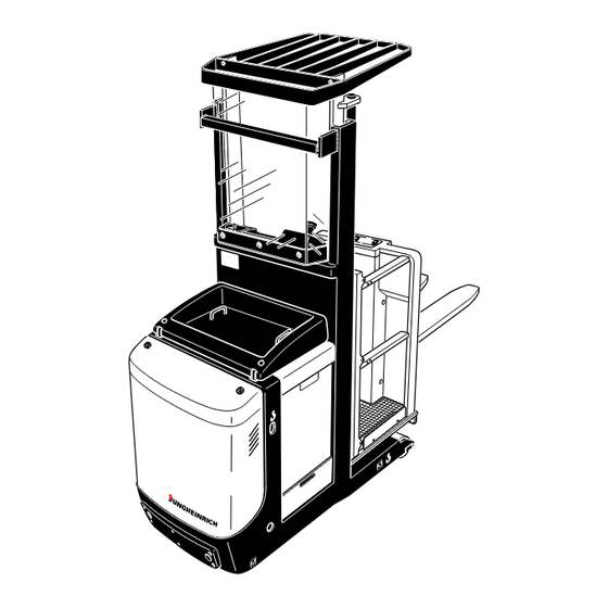
B Description of the truck Design and application The truck described in the present operating instructions is a three-wheel vertical commissioner with a driver stand that can be lifted. The truck is designed for operation on level ground and is intended for transporting and commissioning loads. -
Page 9: Assemblies
Assemblies Item Designation Item Designation 1 o Key “Two-hand operation” 10 o Key-operated control “Pedestrian control in drive direction” 2 t Steering wheel 11 o Key-operated control “Pedestrian control in fork direction” 3 t Information and service display 12 o 2. Master switch (emergency stop) (LISA) 4 t Master switch (emerg. -
Page 10: Truck
Truck Safety installations: Enclosed truck contour. The drive wheel (34) is protected by a sturdy collision guard. The driver stand platform (15) is installed on shock absorbers. The overhead guard (24) (o) protects the driver against any objects that might fall down. - Page 11 Item Designation Item Designation 19o Controller (2nd operating console) 28 o 2. Master switch (emerg. stop) 20 o Pushbutton “Warning signal” 29 t Fork (Horn) (2nd operating console) 21 o Master switch (emerg. stop) 30 o Auxiliary lift 22 o Pushbutton “Lifting” ZG 31 t Safety barrier (from 1,200 mm) 23 o Pushbutton “Lowering”...
-
Page 12: Technical Description - Load Lifting Device
Hydraulic system: The lifting and lowering functions are controlled by means of ope- rating keys. When the lifting function is actuated, the pump unit will start up, delivering hydraulic oil from the oil reservoir to the lifting cylinder. A hydraulic accumulator and a flow control valve allow attenuated lifting and lowering. - Page 13 h 12 h 13 (l 1 )
-
Page 14: Dimensions
Dimensions (all dimensions in mm) Designation Single-stage Two-stage hoist frame hoist frame Height of lowered fork Height of lowered driver stand platform Auxiliary lift 750 / 810 750 / 810 Wheel base 1300 1330 Fork length (standard) 1200 1200 Truck length l + 1715 l + 1745 Front section length... -
Page 15: Standards
EN standards Continuous sound level: 63 dB(A) according to prEN 12053 as stipulated in ISO 4871 The continuous sound level is a value averaged according to standard regulations, taking the sound pressure level into account when driving, lifting and idling. The sound pressure level is measured at the ear. -
Page 16: Labels
Labels Item Designation Accident prevention inspection label (D only) Prohibitive sign “Do not let a second person travel on the truck” Warning sign “Do not reach between the lifting cylinder and the chassis” Rules for shelf operation Load diagram, capacity / load centre / lifting height Label “CAUTION: Low-voltage electronics”... - Page 17 Truck identification plate Item Designation Item Designation Type Drive power in kW Serial No. Customer no. Rated capacity in kg Min./max. battery weight in kg Battery: Voltage V Empty weight without battery in kg Ampere hours Ah Manufacturer Year of manufacture Order no.
-
Page 18: C Transportation And Commissioning
C Transportation and commissioning Transportation by crane Only lifting gear of adequate capacity must be used (transportation weight = dead weight + battery weight; see truck identification plate). Lifting gear attachment points are provided on the chassis (2) and the fork (1) in case the truck is to be lifted or transported by crane. -
Page 19: Moving The Truck With The Drive Unit Inoperative
Moving the truck with the drive unit inoperative This operating mode is not permitted when negotiating inclines and gradients. Malfunction of the electrical system or battery failure causes automatic braking of the truck. If the truck has to be moved after a failure has rendered it immobile, proceed as fol- lows: –... - Page 20 To steer the wheels mechanically (e.g. in narrow aisles), proceed as follows: The truck may only be commissioned by authorised manufacturer’s service after wor- king on the steering drive. – Loosen the screws (5) on the steering drive and carefully remove the cover (6). Make sure that the toothed shaft (at the end of the shaft (7)) is not damaged.
-
Page 22: D Battery - Servicing, Recharging, Replacement
D Battery - Servicing, recharging, replace- ment Safety regulations governing the handling of lead-acid batteries The truck must be parked and rendered safe before any operations on batteries are undertaken (refer to chapter E). Servicing staff: Recharging, servicing and replacing of batteries must only be per- formed by qualified personnel. -
Page 23: Battery Types
Battery types Depending on the truck version, the truck will be supplied with different battery types. The table below shows the capacity of the batteries and also the combinations used as standard equipment: 24 V PzS battery 3 PzS 480 Ah L 24 V PzS battery 3 PzS 560 Ah L 24 V PzS battery... -
Page 24: Charging The Battery
Charging the battery To charge the battery, the truck must be parked in a closed and properly ventilated room. – Expose the battery (refer to section 3). The battery connector (3) and the char- ging cable must only be connected or dis- connected with the truck and the battery charger switched off. -
Page 25: Removing And Installing The Battery
Removing and installing the battery The truck must be parked on level ground. To prevent short-circuits, batteries with ex- posed poles or cell connectors must be covered using a rubber mat. Place the battery connector or the battery cable, respectively, in such a way that they will not catch be- hind any truck protrusions when the battery is withdrawn. -
Page 26: Information And Service Display (Lisa)
Information and service display (LISA) Battery discharge indicator: The charging state of the battery (8) is indicated in 10% increments on the information and service display. The standard setting of the battery di- scharge indicator / discharge monitor is made using standard batteries. When using maintenance-free batteries, the display must be set so that the “T”... -
Page 28: Safety Regulations Governing The Operation Of The Fork Lift Truck
E Operation Safety regulations governing the operation of the fork lift truck Driving permission: The fork lift truck must only be operated by persons who have been trained in the operation of trucks, who have demonstrated to the user or his re- presentative their capability of moving and handling loads, and who have expressly been charged by the user or his representative with the operation of the truck. -
Page 29: Description Of The Operating Controls And Indicators
Description of the operating controls and indicators Item Operating control or indica- Function t Controls the direction of travel as well as 1 Controller the travelling speed. o Releases the lifting and driving functions 2 Key “Two-hand operation” when pressed (in the rail guidance mode with aisle recognition). - Page 31 Item Operating control or indica- Function o Optional equipment for the “Operator wal- 14 Key-operated control “Operator walking / drive king” mode: direction” The truck starts moving in direction (V) with the operator walking alongside (cut-back speed). o Optional equipment for the “Operator wal- 15 Key-operated control “Operator walking / fork king”...
- Page 33 Item Operating control or indica- Function o Steers the truck. 24 Steering wheel (2nd operating console) o Releases the lifting and driving functions 25 Pushbutton “Two-hand operation” when pressed (in the rail guidance mode (2nd operating console) with aisle recognition). o Controls the direction of travel as well as 26 Controller (2nd operating console)
-
Page 35: Starting Up The Truck
Starting up the truck Before starting or operating the truck, or before lifting any loads, the driver has to make sure that nobody is within the danger area. Checks and operations to be performed before starting daily work – Visually check the entire truck (especially the wheels and the load lifting equipment) for visible damage. - Page 36 Switching on the truck When the truck is parked, the running surface of the tyres will flatten. The flattening will disappear after a short operating time of the truck. – Step on to the standing platform. – Switch on the master switch (6) by turning it in the direction of the arrow (if neces- sary, all master switches).
-
Page 37: Operation Of The Fork Lift Truck
Operation of the fork lift truck Safety regulations applicable when operating the truck Driving lanes and work areas: Only such lanes and routes that are specially alloca- ted for truck traffic must be used. Unauthorized persons must stay away from work areas. -
Page 38: Driving, Steering, Braking
To avoid falling down: The driver must not leave the driver position while the driver stand platform is lifted - climbing over onto structural works or other vehicles is not permitted. In the case of longitudinal deposition, it is possible that packages cannot be reached from the operator platform without additional measures. - Page 39 Emergency stop – Press the master switch (6). This will switch off all electric functions. Deadman key Driving and lifting (main lift) is only possible when the deadman key (16) / (17) is pres- sed. For the auxiliary lifting function (o), the deadman key need not be pressed. Safety barriers If the lifting height exceeds 1200 mm, driving and lifting (main lift) is only possible when the safety barriers (18) are closed.
- Page 40 Driving Do not drive the truck unless the hoods are closed and locked in the stipulated man- ner. Always lower the load when driving outside the aisles. Always follow the operational sequences described below. – Start up the truck (refer to section 3). –...
- Page 41 Steering – Turn the steering wheel (3) to the left or the right. Depending on the lifting height and the residual capacity (see the load diagram), the steering angle may be limited to ±5°. If the steering angle is greater than ±5°, the lifting function will be deactivated above this specific height.
-
Page 42: Key-Operated Control Of The Truck - "Operator Walking" (O)
Key-operated control of the truck - “Operator walking” (o) When the truck is under key-operated control and the operator walks beside the truck, he must ensure that the steering unit points straight ahead and that he cannot be crushed between the truck and other obstacles. When using this operating mode, the operator must stay beside the truck. -
Page 43: Picking Up And Setting Down Loads
Picking up and setting down loads Before picking up a load, the driver has to make sure that it is correctly palletised and that the capacity of the truck is not exceeded. The driver must always stand on the driver stand platform when operating the con- trols to pick up and set down loads. -
Page 44: Auxiliary Lift (O)
Auxiliary lift (o) The controls for operating the auxiliary lifting function are integrated in the lifting unit. The auxiliary lifting function allows the fork to be lifted without lifting the driver stand platform. Lifting – Press the “Lift fork” key (31 and 33) until the required lifting height has been rea- ched. -
Page 45: Safe Parking Of The Truck
Safe parking of the truck If the truck is left unattended, even for only short periods of time, it must be rendered safe. Never park the truck on a slope or incline. The fork must always be completely lowe- red. –... -
Page 46: Entering Narrow Aisles
Entering narrow aisles Do not enter any aisle unless it is vacant. Stop the truck immediately when per- sons are present in the aisle! Truck with rail guidance (o) – Drive the truck slowly up to the aisle so that it is in true alignment with the ais- Heed the marks on the driving lane (e.g. -
Page 47: Information And Service Display (Lisa)
Information and service display (LISA) The display (40) of the LC information and service display (“LISA”) is used to indicate operating data, the charging state of the battery, the operating hours and service and diagnosis data. Two light-emitting diodes (LEDs (38) and (39)) are arranged under the display as warning lamps. -
Page 48: Displays
Displays The display shows operating data and fault messages. The user menu permits the setting of the following driving parameters: Here, the time between max. operation of the controller ACCELERATION and 100% control by the electronics is set. This parameter can only be adjusted by the manufacturer's RELEASE BRAKE service personnel. -
Page 49: Changing Truck Parameters
Changing truck parameters Changing truck parameters will also change the driving behaviour of the truck. This must be taken into account when commissioning the truck! Parameters may only be changed while the truck is at a standstill and no lifting mo- vements are performed. -
Page 50: Fault Location
Fault location This chapter enables the operator to locate and rectify minor faults and malfunctions, or the effects of operating errors. When trying to locate a fault, proceed in the order shown in the table. Fault Possible cause Remedial action –... - Page 51 E 24...
-
Page 52: F Maintenance Of The Fork Lift Truck
F Maintenance of the fork lift truck Operational safety and environmental protection The checks and servicing operations contained in this chapter must be performed in accordance with the intervals as indicated in the servicing checklists. Modifications of fork lift truck assemblies, especially of the safety installations, are not permitted. - Page 53 Work on the electric system: Work on the electric system of the truck must only be performed by personnel specially trained for such operations. Before commencing any work on the electric system, all measures required to prevent electric shocks have to be taken. For battery-operated fork lift trucks, the truck must also be depowe- red by removing the battery plug.
-
Page 54: Servicing And Inspection
Servicing and inspection Thorough and expert servicing is one of the most important preconditions for safe operation of the fork lift truck. The neglect of regular servicing intervals can lead to fork lift truck failure and constitutes a potential hazard to personnel and equipment. The indicated servicing intervals are based on single-shift operation under normal operating conditions. -
Page 55: Maintenance Intervals
Maintenance intervals Maintenance intervals = t W M M M standard = k 1 3 6 12 cold store Chassis 1.1 Check all load bearing elements for damage and super- 1.2 Check all bolted connections struct. 1.3 Check platform for correct functioning and damage Drive unit 2.1 Check the transmission for noises and leakage 2.2 Check the transmission oil level... - Page 56 Maintenance intervals = t W M M M standard = k 1 3 6 12 cold store Battery 9.1 Check acid density, acid level and cell voltage 9.2 Check the terminals for secure attachment and apply grea- 9.3 Clean battery connections, check for tight seat 9.4 Check the battery cables for damage, renew, if necessary Lifting 10.1 Performance, wear and adjustment check...
-
Page 57: Lubrication Schedule
Lubrication schedule 1,4 l M = 110 Nm Hydraulic oil filling leve Gliding surfaces Grease nipples Lift. height in mm Filling level in l Filler plug for hydraulic oil Filler plug for transmission oil 1000 Drain plug for transmission oil 1600 Cold store usage 1900... -
Page 58: Fuels, Coolants And Lubricants
Fuels, coolants and lubricants Handling consumption type material: Consumption type material must always be handled properly. Manufacturer's instructions to be observed. Improper handling is injurious to health, life, and environment. Consumption type ma- terials must be stored in adequate containers. They might be inflammable and, the- refore, must not come into contact with hot components or open fire. -
Page 59: Instructions For The Servicing Operations
Instructions for the servicing operations Preparing the truck for the performance of servicing and maintenance operations All required safety measures must be taken to prevent any accidents in the course of the servicing and maintenance operations. The following preparatory operations must be performed: –... -
Page 60: Opening The Door To The Electrical System
The drive unit and the hydraulic system can be accessed for servicing purposes. Installation occurs in the reverse order of steps. Do not drive the truck unless the hoods are closed and locked in the stipulated man- ner. Opening the door to the electrical system –... -
Page 61: Checking The Transmission Oil Level / Changing The Transmission Oil
Checking the transmission oil level / changing the transmission oil Always be especially careful when handling consumption-type materials. Always heed section 5.1. Change the transmission oil when the truck is at operating temperature. – Start up the truck (refer to chapter E). –... -
Page 62: Checking The Electric Fuses
Checking the electric fuses 13 14 15 16 17 – Prepare the truck for the ser- vicing and maintenance operati- (refer to section 6.1). – Open the door to the electrical system (refer to section 6.4). Referring to the table, check all fu- ses for correct rating and damage;... -
Page 63: Recommissioning The Truck
Recommissioning the truck Recommissioning of the truck following the performance of cleaning or maintenance work is permitted only after the following operations have been performed: – Check the horn for proper functioning. – Check the master switch for correct functioning. –... -
Page 64: Recommissioning The Truck
Recommissioning the truck – Thoroughly clean the fork lift truck. – Lubricate the fork lift truck according to the lubrication chart (refer to chapter F). – Clean the battery. Grease the pole screws using pole grease and reconnect the battery. –...
Need help?
Do you have a question about the ECP 100-3 and is the answer not in the manual?
Questions and answers