Jungheinrich EKS 110 Operating Instructions Manual
Electric vertical stockpicker
Hide thumbs
Also See for EKS 110:
- Operating instructions manual (105 pages) ,
- Operating instructions manual (224 pages)
Table of Contents
Advertisement
Advertisement
Table of Contents

Related Manuals for Jungheinrich EKS 110


Summary of Contents for Jungheinrich EKS 110
- Page 1 EKS 110 03.09 - Operating instructions 51141993 03.09...
- Page 2 Our trucks are subject to ongoing development. Jungheinrich reserves the right to al- ter the design, equipment and technical features of the system. No guarantee of par- ticular features of the truck should therefore be assumed from the present operating instructions.
- Page 3 Copyright Copyright of these operating instructions remains with JUNGHEINRICH AG. Jungheinrich Aktiengesellschaft Am Stadtrand 35 22047 Hamburg - Germany Tel: +49 (0) 40/6948-0 www.jungheinrich.com...
-
Page 4: Table Of Contents
Table of contents Correct Use and Application ........... Truck Description ..............Application ....................Travel direction definition................. Assemblies and Functional Description........... Assembly Overview ................. Assembly description................Technical Specifications ................Performance data ..................Weights....................Tyre type....................Dimensions ....................EN norms....................Application ....................Labels and Decals ................... - Page 5 Operator position control station in drive direction ........Second control station (o) in load direction ..........Auxiliary lift controls................. Pedestrian EKS 110 with gates ............... Deadman button and gate ............... Starting up the truck ................Checks and operations to be performed before starting daily operation .
- Page 6 Front panel assembly and disassembly ..........Electrical system..................Checking electrical fuses................. Restoring the truck to service after maintenance and repairs ....Decommissioning the industrial truck ............Before taking the truck out of service ............Action to be taken during decommissioning: ........... Restoring the truck to service after decommissioning ......
- Page 8 Appendix JH Traction Battery Operating Instructions These operating instructions apply only to Jungheinrich battery models. If using another brand, refer to the manufacturer's operating instructions.
-
Page 10: A Correct Use And Application
A Correct Use and Application WARNING! The “Guidelines for the Correct Use and Application of Industrial Trucks” (VDMA) are supplied with the truck. The guidelines form part of these operating instructions and must be observed. National regulations apply in full. The truck described in the present operating instructions is an industrial truck de- signed for lifting and transporting loads. -
Page 12: B Truck Description
The rack systems must be set up for the EKS 110. The safety distances stipulated by the manufacturer (e.g. EN 1726-2 item 7.3.2) must be observed. -
Page 13: Assemblies And Functional Description
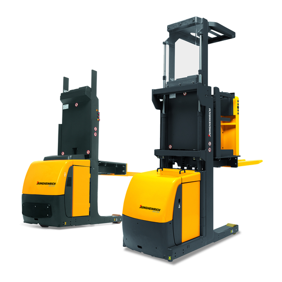
Assemblies and Functional Description Assembly Overview Item Description t Overhead guard o Duplex mast t Controller t Gate (from 1200 mm) t Simplex mast t Fork t Operator platform t Electrical system cover o Guide wheels t Front panel t Drive wheel t Battery cover t Driver's display t Standard equipment... -
Page 14: Assembly Description
Assembly description Safety Mechanisms The truck has an enclosed geometry. The drive wheel is surrounded by a solid skirt. The operator platform is cushioned against impacts. The overhead guard protects the driver from any falling objects. Gates on either side of the operator platform cut out all travel and lifting operations beyond a lift height of 1200 mm. -
Page 15: Technical Specifications
Technical Specifications Technical data specified in accordance with VDI 2198. Technical modifications and additions reserved. All data applies to the L and Z versions unless otherwise indicated. Performance data EKS 110 EKS 110 EKS 110 EKS 110 Description (100 E) -
Page 16: Weights
Weights EKS 110 EKS 110 EKS 110 EKS 110 Description (100 E) (160 E) (190 E) (280 ZZ) Truck weight including bat- 1756/ 1934/ 1970/ 2270/ tery L/Z 1859 2036 2072 2390 Axle load with load front/rear 481/ 461/ 461/... -
Page 17: Dimensions
Dimensions... - Page 18 EKS 110 EKS 110 EKS 110 EKS 110 Description (100 E) 160 E) (190 E) (280 ZZ) Load centre of gravity dis- tance Load distance Wheelbase 1300 1385 Mast height retracted 2260 2560 2251 1660 Lift 1000 1600 1900 2800...
-
Page 19: En Norms
EN norms Noise emission level – EKS 110: 61 dB(A) in accordance with EN 12053 as harmonised with ISO 4871. The noise emission level is calculated in accordance with standard procedures and takes into account the noise level when travelling, lifting and when idle. The noise level is measured at the level of the driver's ear. -
Page 20: Labels And Decals
Labels and Decals Warnings and notices such as load charts, strap points and data plates must be legi- ble at all times. Replace if necessary. Item Description "Do not reach through the mast" warning Truck data plate Capacity Plate, Capacity / Load Centre of Gravity / Lift Height Test plaque (o) “Danger of trapping”... -
Page 21: Truck Data Plate
Truck data plate Item Description Item Description Type Manufacturer Serial number Min./max. battery weight (kg) Rated capacity (kg) Drive output (kW) Battery voltage (V) Load centre of gravity (mm) Net weight w.o. battery (kg) Year of manufacture Manufacturer’s logo Option For queries regarding the truck or ordering spare parts always quote the truck serial number. -
Page 22: C Transport And Commissioning
C Transport and Commissioning Lifting by crane Lifting the truck by crane WARNING! Improper lifting by crane can result in accidents The use of unsuitable lifting gear can cause the truck to crash when being lifted by crane. Prevent the truck and mast from striking other objects when they are being raised, and avoid any uncontrolled movement. -
Page 23: Securing The Truck For Transport
Securing the Truck for Transport Securing the truck for transport WARNING! Accidental movement during transport Improper fastening of the truck and mast during transport can result in serious acci- dents. Loading must be carried out by specially trained staff in accordance with recom- mendations contained in Guidelines VDI 2700 and VDI 2703 In each case correct measurements must be made and appropriate safety measures adopted. -
Page 24: Using The Truck For The First Time
Using the truck for the first time Preparing the truck for commissioning Procedure • Check the equipment is complete. • If necessary install the battery. (see "Battery removal and installation" on page 27) Only operate the truck with battery current. Rectified AC current will damage the electronic components. -
Page 25: Operating The Truck Without Its Own Drive System
Operating the truck without its own drive system Releasing the brake CAUTION! Uncontrolled truck movement Do not release the brake on slopes or inclines. Apply the brake again when you reach your destination. Do not park the truck with the brake released. Tools and Material Required –... -
Page 26: D Battery Maintenance, Charging & Replacement
D Battery Maintenance, Charging & Re- placement Safety regulations for handling acid batteries Maintenance personnel Batteries may only be charged, serviced or replaced by trained personnel. This oper- ator manual and the manufacturer’s instructions concerning batteries and charging stations must be observed when carrying out the work. Fire protection Do not smoke and avoid naked flames when handling batteries. - Page 27 WARNING! Using unsuitable batteries can cause accidents The weight and dimensions of the battery have a considerable effect on the opera- tional safety and capacity of the industrial truck. Changing the battery features re- quires the manufacturer’s approval, as compensating weights are required if smaller batteries are fitted.
-
Page 28: Battery Types
Battery types Depending on the model, the truck will be supplied with different battery types. The following table shows which combinations are included as standard: Battery type Capacity Weight 24 volt battery (maintenance-free) 4 EPzV 480 Ah 480 kg 24 volt battery 4 EPzS 560 Ah 24 volt battery 4 EPzS 620 Ah... -
Page 29: Charging The Battery
Charging the battery Charging the battery WARNING! The gases produced during charging can cause explosions The battery produces a mixture of nitrogen and hydrogen (electrolytic gas) during charging. Gassing is a chemical process. This gas mixture is highly explosive and must not be ignited. -
Page 30: Battery Removal And Installation
Battery removal and installation Removing the battery WARNING! Accident risk during battery removal and installation Due to the battery weight and acid there is a risk of trapping or scalding when the bat- tery is removed and installed. Note the "Safety regulations for handling acid batteries" section in this chapter. Wear safety shoes when removing and installing the battery. - Page 31 Battery installation Requirements – Truck parked. – Battery lock removed. Tools and Material Required – Crane or forklift truck – Crane slings – Battery replacement trolley (o) Procedure • Installing the battery with a crane or forklift truck • Attach the hooks of the crane slings to the strap eyes (5) on the battery. The discharged crane slings must not fall onto the battery cells.
-
Page 32: Driver's Display
Driver's display Battery discharge indicator The battery charge status is shown on the driver's display via a battery symbol (7). When a battery is discharged to the permissible discharge level, the battery symbol (7) is empty. The standard setting for the battery discharge indicator (8) is based on standard batteries. -
Page 34: E Operation
E Operation Safety Regulations for the Operation of the Forklift Truck Driver authorisation The truck may only be used by suitably trained personnel, who have demonstrated to the proprietor or his representative that they can drive and handle loads and have been authorised to operate the truck by the proprietor or his representative. -
Page 35: Displays And Controls
Displays and Controls Operator position control station in drive direction Item Control / Display Function t For holding A4 paper Clip board t Lowers the operator platform and forks. Lower button t Lifts the operator platform and forks. Lift button o Raises the forks Aux. - Page 36 Item Control / Display Function o Pedestrian mode optional feature: Lifts the Pedestrian mode lift button operator platform and forks. o Pedestrian mode optional feature, travel is Drive direction pedes- trian touch mode continued as operator walks beside in drive direction (slow travel).
-
Page 37: Second Control Station (O) In Load Direction
Second control station (o) in load direction Item Control / Display Function t Lowers the operator platform and forks. Lower button t Lifts the operator platform and forks. Lift button o Raises the forks. Aux. lift “raise” button o Lowers the forks. Aux. - Page 38 Item Control / Display Function Emergency Disconnect o Pedestrian mode optional feature: Disconnects the supply current and deactivates all electrical functions, causing the truck to brake automati- cally. o Steers the truck. Steering wheel (2nd control station) o Releases lifting and travel when pressed (in rail Two-hand operation button (2nd control sta- guidance mode with aisle recognition).
-
Page 39: Auxiliary Lift Controls
Auxiliary lift controls Item Control / Display Function o Raises the forks Aux. lift “raise” button o 2nd control station o Lowers the forks Aux. lift “lower” button o 2nd control station o Raises/lowers the forks (aux. lift) Use in con- Two-hand operation, FEM fork raise/lower junction with buttons 4 and 5. -
Page 40: Pedestrian Eks 110 With Gates
Pedestrian EKS 110 with gates Item Control / Display Function o Pedestrian mode optional feature: Lowers the Pedestrian mode lower button operator platform and forks. o Pedestrian mode optional feature: Lifts the Pedestrian mode lift button operator platform and forks. -
Page 41: Deadman Button And Gate
Deadman button and gate Item Control / Display Function o Open: Lifting and travel inhibited from a lift Gate height of 1200 mm. Closed: Lifting and travel released. t Released: Travel inhibited, or truck deceler- Deadman button ates. Applied: Travel released. o Released: Travel inhibited, or truck deceler- 2nd control station deadman button... -
Page 42: Starting Up The Truck
Starting up the truck Checks and operations to be performed before starting daily opera- tion Visual inspection before starting daily operation WARNING! Damage and other truck or attachment (special equipment) defects can result in accidents. If damage or other truck or attachment (special equipment) defects are discovered during the following checks, the truck must be taken out of service until it has been repaired. -
Page 43: Individual Assembly Of The Second Control Station Control Panels
• Test the warning signal button (6). • Test the deadman button (27, 28) and controller (13). The truck is now operational. The steering is set straight-ahead. Individual assembly of the second control station control panels The left and right-hand control panels of the second control station (O) can be set to two different heights "A"... -
Page 44: Industrial Truck Operation
Industrial Truck Operation Safety regulations for truck operation Travel routes and work areas Only use lanes and routes specifically designated for truck traffic. Unauthorised third parties must stay away from work areas. Loads must only be stored in places special- ly designated for this purpose. -
Page 45: Emergency Disconnect, Travel, Steering, Braking
Load aids may only be walked on if suitable safety devices such as pallet guard and pallet tipover safety mechanisms are in place. Emergency Disconnect, Travel, Steering, Braking 4.2.1 Emergency Disconnect Applying the Emergency Disconnect Procedure • Press the Emergency Disconnect (19, 12, 22). Do not use the Emergency Disconnect (19, 12, 22) as a service brake. - Page 46 4.2.3 Travel Requirements – Truck started up. – Beyond a lift height of 1200 mm the gates (26) must be closed to enable travel and lifting (main lift). – Panels closed and locked correctly. Procedure • Press the deadman button (27, 28). •...
- Page 47 Trucks with forks (version L) – Maximum speed up to platform height of 1200 mm – From platform height of 1200 mm at steering angle < ± 10 degrees: Travel speed 4 km/h (slow travel) at steering angle > ± 10 degrees: Travel speed 2.5 km/h (slow travel) Trucks with auxiliary lift (version Z) With auxiliary lift <...
-
Page 48: Travelling In Pedestrian Touch Mode (O)
Travelling in pedestrian touch mode (o) CAUTION! Risk of trapping Steering set straight-ahead. The operator must always stand beside the truck during pedestrian operation. There must be no persons standing between the truck and any obstacles. There must be no persons on the operator platform. Procedure •... -
Page 49: Operator Platform Lifting And Lowering
Operator platform lifting and lowering Operator platform lifting Procedure • Press the lift button (3) until you reach the desired lift height. On trucks with the pedestrian touch mode option (o), version L, the deadman but- ton (27, 28) must be applied in addition to the lift button (3) in order to lift to the max- imum height. - Page 50 Operator platform lowering Procedure • Press the lower button (2) until you reach the desired lift height. On trucks with an auxiliary mast and FEM 2A forged forks, the operator platform can only be lowered if the lower button (2) and the two-hand operation button (15) are pressed simultaneously.
-
Page 51: Auxiliary Lift - Raising And Lowering
Auxiliary Lift – raising and lowering The auxiliary lift enables the forks to be raised without having to raise the operator platform. Auxiliary lift - raise Procedure • Press the auxiliary lift raise button (4) until you reach the desired lift height. - Page 52 Auxiliary lift - lower Procedure • Press the auxiliary lift lower button (5) until you reach the desired lift height. On trucks with an auxiliary mast and FEM 2A forged forks, the operator platform can only be raised or lowered if the auxiliary lift raise (4) or auxiliary lift lower (5) and the two-hand operation (15, 21) buttons are pressed simultaneously.
-
Page 53: Lifting And Lowering In Pedestrian Touch Mode
Lifting and lowering in pedestrian touch mode In pedestrian touch mode lifting and lowering can be operated from either side of the truck as an optional feature. On trucks with forks (version L) the entire operator platform rises or lowers with the forks in pedestrian touch mode lifting/lowering. - Page 54 4.6.2 Lifting and lowering the forks (version Z) Lifting CAUTION! Risk of trapping Steering set straight-ahead. The operator must always stand beside the truck during pedestrian operation. There must be no persons standing between the truck and any obstacles. There must be no persons on the operator platform.
- Page 55 Procedure • Press the lift button (23) until you reach the desired lift height. Lowering WARNING! Ensure there are no other people standing underneath the raised load and driv- er's cab. Do not stand on the load handler. Do not lift other people on the load handler. Instruct other people to move out of the hazardous area of the truck.
-
Page 56: Lifting And Lowering The Operator Platform With Lift Cutout (O)
Lifting and lowering the operator platform with lift cutout (o) On trucks with the lift cutout option (o) the operator platform rises to a fixed cutout height which is less than the maximum lift height. Lifting Procedure • Press the lift button (3) until you reach the fixed cutout height. •... -
Page 57: Lifting And Depositing Load Units
Lifting and depositing load units Do not lift long loads at an angle. Do not walk on the load section (except for trucks with the pallet guard option (o)) Lifting load units Requirements – Load unit correctly palletised. – Fork spread for the pallet checked and adjusted if necessary. –... -
Page 58: Adjusting The Forks (O)
Adjusting the forks (o) On trucks equipped with the fork carriage with adjustable and detachable forks op- tion, the fork spread must be checked and adjusted if necessary before lifting loads. Adjusting the forks Procedure • Lift up the locking lever (30). •... -
Page 59: Walk-On Load Section With Pallet Guard (O)
4.10 Walk-on load section with pallet guard (o) Lifting pallets CAUTION! Risk of crashing with walk-on pallets Only walk on a pallet if it has a pallet guard (o). Beyond lift heights > 1200 mm the gates must be closed to enable travel, lifting and lowering (Main Lift). -
Page 60: 4.11 Parking The Truck Securely
• Press the railing strap (36) down. • Turn the lever for the stop bolts (35) down again. • Move the railing strap (36) until the locking pins of the stop bolts engage. The pallet is now raised. 4.11 Parking the truck securely Parking the truck securely CAUTION! An unsecured truck can cause accidents... -
Page 61: 4.12 Negotiating Narrow Aisles
4.12 Negotiating narrow aisles 4.12.1 Safety notices for travelling in narrow aisles WARNING! Unauthorised entry of narrow aisles by other trucks or people can cause acci- dents Unauthorised personnel must not enter narrow aisles (truck lanes in racking systems with safety distances < 500 mm), nor must any personnel cross through them. Carry out a daily inspection of the safety mechanisms on the truck or the racking system to avoid hazards and to protect personnel. - Page 62 4.12.2 Rail guided trucks (o) Operating a rail-guided truck in a narrow aisle Procedure • Drive slowly up to the rack aisle until the truck is aligned with the aisle. • Note the markings attached along the route (e.g. aisle centre line).
-
Page 63: Trucks With Rail Guidance (O) And Aisle Recognition (O)
4.13 Trucks with rail guidance (o) and aisle recognition (o) Notes on rail-guided operation Trucks with the light button aisle recognition option can travel at maximum speed even beyond the 1200 mm operator platform height (or 520 mm for trucks with auxil- iary lift). - Page 64 • When the truck has come to rest, the two-hand operation button (15) must be pressed in order for travel and lifting/lowering to continue. From this point on, the steering is overridden and the drive wheel is automatically held in the straight- ahead position.
- Page 65 duced to 2.5 km/h (slow travel) when the truck travels over the permanent magnets in the ground (normally at the end of a narrow aisle or in the transfer aisle. The end of aisle safety device indicator (16) lights up. The travel speed reduction is activated whenever the truck travels over ground magnets, irrespective of the travel direction and the order in which the magnets are passed over.
-
Page 66: Emergency Lowering
Emergency lowering Mast emergency lowering CAUTION! Risk of injury from the mast Instruct other people to vacate the hazardous area during emergency lowering. Only start the truck when the error has been rectified. Requirements – Required tools and materials – 3 mm diameter pin, tool etc. Procedure •... -
Page 67: Displays
Displays Driver's display The driver's display represents the interface between the operator and the truck. It acts as a display and control unit for the operator and customer service engineer alike. Pressing the four short stroke keys (59, 58 , 57, 56) operates the driver's display and hence the truck. - Page 68 Item Description Service mode is active (yellow spanner icon), Service interval expired (icon flashing) Steering angle display in 30° increments in arrow form Travel direction display No function Time display (hours: minutes) Battery discharge status Discharge indicator Set speed (drive direction) for current profile (in bars from 1 to 5) No function Profile number (travel profile 1, 2 or 3) Warning and fault indication as text (14 segment display) and data registra-...
-
Page 69: Cancode Keypad (O)
CANCODE keypad (o) CANCODE keypad The keypad consists of 10 digit keys, a Set key and a o key. The O key indicates the follow operating statuses via a red / green LED: – Code lock function (starting up the truck) –... -
Page 70: Parameters
Parameters The keypad enables parameters to be adjusted in programming mode. Parameter Groups The parameter number is composed of three digits. The first digit refers to the param- eter group as shown in Table 1. The second and third digits are numbered in se- quence from 00 to 99. - Page 71 Parameter list Function Setting range Standard Procedure setting Change master code. 0000 - 9999 or 7295 – (LED 60 The length (4-6 digits) 00000 - 99999 flashes) Enter of the master code current code also pre-determines 000000 - – Confirm (Set the length of the oper- 999999 ator code (4-6 digits).
- Page 72 Function Setting range Standard Procedure setting 0000 - – (LED 60 9999or00000 - flashes) 99999or00000 Enter the cur- 0 - 999999 rent code – Confirm (Set – (LED 61 flashes) Enter a new code – Confirm (Set – (LED 62 flashes) Re-enter the code...
- Page 73 – Operator code to be changed does not exist. – Operator code should be changed to another operating code which already exists. – Tried to delete an operator code that does not exist. – Code memory full.
-
Page 74: Changing Truck Settings
Changing truck settings Changing the truck settings will affect the behaviour of the truck. This must be taken into account when starting up the truck. Settings may only be changed when the truck is stationary and not lifting. The driver’s display can also be used to change certain truck parameters (accelera- tion, coasting brake, reverse braking, drive direction speed, fork direction speed and lift speed) and hence the truck’s characteristics. -
Page 75: Troubleshooting
Troubleshooting This chapter allows the user to identify and rectify basic faults or the effects of incor- rect operation. When trying to locate a fault, proceed in the order shown in the table. Fault Possible Cause Action Truck does not start –... - Page 76 If the fault cannot be rectified after carrying out the above procedures, notify the manufacturer’s service department, as further troubleshooting can only be per- formed by specially trained and qualified service personnel.
-
Page 78: F Truck Maintenance
F Truck Maintenance Operational Safety and Environmental Protection The checks and servicing operations contained in this chapter must be performed in accordance with the intervals as indicated in the servicing checklists. Any modification to the forklift truck assemblies, in particular the safety mecha- nisms, is prohibited. -
Page 79: Maintenance Safety Regulations
Maintenance Safety Regulations Maintenance personnel The truck should only be serviced and repaired by the manufacturer's specialist cus- tomer service personnel who have been trained to do this. We therefore recommend that you enter into a maintenance contract with the manufacturer’s local sales office. Lifting and jacking up WARNING! Lifting and jacking up the truck safely... - Page 80 cause malfunctions. Do not clean with pressurised water. After cleaning, carry out the operations detailed in “Recommissioning the truck after cleaning or maintenance work” ((see "Restoring the truck to service after mainte- nance and repairs" on page 95)).
- Page 81 Electrical system WARNING! Accident risk Only suitably trained electricians may operate on the truck's electrical system. Before working on the electrical system, take all precautionary measures to avoid electric shocks. Always disconnect the battery before starting cleaning operations. WARNING! Electric currents can cause accidents Make sure the electrical system is voltage-free before starting work on it.
- Page 82 Consumables and used parts CAUTION! Consumables and used parts are an environmental hazard Used parts, oils and fuels must be disposed of in accordance with the relevant envi- ronmental protection regulations. To change the oil contact the manufacturer's cus- tomer service department, who have been specially trained for this task. Note the safety regulations when handling these materials.
- Page 83 Wheels WARNING! The use of wheels that do not match the manufacturer's specifications can re- sult in accidents. The quality of wheels affects the stability and performance of the truck. Uneven wear affects the truck's stability and increases the stopping distance. When replacing wheels make sure the truck is not skewed.
- Page 84 Hydraulic hoses WARNING! Brittle hydraulic hose lines can cause accidents The hoses must be replaced every six years. The manufacturer's customer service department is specially trained to carry out these operations. Comply with the safety regulations for hydraulic hose lines in accordance with ZH 1/74.
- Page 85 Lift chains WARNING! Non-lubricated and incorrectly cleaned lift chains can cause accidents Lift chains are safety-critical parts. They must not contain any serious contamination. Lift chains and pivot pins must always be clean and well lubricated. Lift chains should only be cleaned with paraffin derivatives e.g. petroleum or diesel fuels.
-
Page 86: Servicing And Inspection
The application conditions of an industrial truck have a considerable impact on the wear of the service components. We recommend that a Jungheinrich customer service adviser carries out an applica- tion analysis on site to work out specific service intervals to prevent damage due to wear. -
Page 87: Maintenance Checklist
6.1 Visually inspect rollers, slide pieces and stops. 6.2 Check operation, wear and setting. 6.3 Test hydraulic system. 6.4 Check the hydraulic auxiliary unit (not on EKS 110 LG). Check that hose and pipe lines and their connections are secure, check for leaks and damage. - Page 88 Maintenance Intervals Standard = t W A B C Cold store = k Braking 6.9 Replace hydraulic oil filter. Agreed performance levels 7.1 Lubricate truck in accordance with Lubrication Schedule. 7.2 Carry out a test run with rated load. 7.3 Demonstration after servicing. Steering system 8.1 Test the electric steering and its components Check the steering head bearings, steering play and steering tooth-...
-
Page 89: Lubricants And Lubrication Schedule
Lubricants and Lubrication Schedule Lubrication Schedule 1,05 l g Contact surfaces k Cold Store Application s Grease nipple b Transmission oil filler neck a Transmission oil drain plug Hydraulic oil filler neck 1 Compound ratio for cold store usage 1:1 2 Capacity (see "Consumables"... -
Page 90: Handling Consumables Safely
in the oil. Handling consumables safely WARNING! Improper handling is hazardous to health, life and the environment Consumables can be flammable. Keep consumables away from hot components and naked flames. Always keep consumables in prescribed containers. Always fill consumables in clean containers. Do not mix up different grades of consumable. -
Page 91: Consumables
Consumables and used parts CAUTION! Consumables and used parts are an environmental hazard Used parts, oils and fuels must be disposed of in accordance with the relevant envi- ronmental protection regulations. To change the oil contact the manufacturer's cus- tomer service department, who have been specially trained for this task. Note the safety regulations when handling these materials. -
Page 92: Maintenance And Repairs
Maintenance and repairs Preparing the truck for maintenance and repairs All necessary safety measures must be taken to avoid accidents when carrying out maintenance and repairs. The following preparations must be made: Procedure • Park the truck on a level surface. •... -
Page 93: Tightening The Wheel Nuts
Tightening the wheel nuts The wheel nuts on the drive wheel must be retightened in accordance with the main- tenance intervals indicated in the maintenance checklist. Tightening the wheel nuts Requirements – Prepare the truck for maintenance and repairs ((see "Preparing the truck for main- tenance and repairs"... -
Page 94: Mast Retainer Assembly And Removal
Mast retainer assembly and removal The truck has four (for simplex mast 2) retaining blocks to secure the mast. Mast retainer assembly Requirements – Prepare the truck for maintenance and repairs ((see "Preparing the truck for main- tenance and repairs" on page 89)). Tools and Material Required –... -
Page 95: Front Panel Assembly And Disassembly
Tighten the screws manually so that they cannot be undone by normal impacts caused during operation. The mast retainer is now removed. Front panel assembly and disassembly Front panel disassembly Tools and Material Required – Allen key, size 6 Procedure •... -
Page 96: Electrical System
Electrical system Exposing the electrical system Procedure • Open the battery panel, (see "Exposing the battery" on page 25). • Hold the top of the electrical system cover (9) and pull it away from the truck until the top two snap lock connections are disengaged. -
Page 97: Checking Electrical Fuses
Checking electrical fuses Checking and replacing fuses Requirements – Prepare the truck for maintenance and repairs – Expose the electrical system Procedure • Check fuse ratings and check for damage. • Replace any damaged fuses in accordance with the table. •... -
Page 98: Restoring The Truck To Service After Maintenance And Repairs
Restoring the truck to service after maintenance and repairs After cleaning or repair work, the truck may only be restored to operation once the following operations have been performed. Procedure • Clean the truck thoroughly. • Lubricate the truck according to the lubrication schedule, (see "Lubrication Sched- ule"... -
Page 99: Decommissioning The Industrial Truck
Decommissioning the industrial truck If the truck is to be out of service for more than a month, e.g. for commercial rea- sons, it must be stored in a frost-free and dry room. All necessary measures must be taken before, during and after decommissioning as described hereafter. WARNING! Lifting and jacking up the truck safely In order to raise the truck, the lifting gear must only be secured to the points specially... -
Page 100: Before Taking The Truck Out Of Service
Before taking the truck out of service Procedure • Clean the truck thoroughly. • Test the brakes. • Check the hydraulic oil level and replenish if necessary, (see "Consumables" on page 88). • Apply a thin layer of oil or grease to any non-painted mechanical components. •... -
Page 101: Action To Be Taken During Decommissioning
Action to be taken during decommissioning: Every 2 months: Procedure • Charge the battery, (see "Charging the battery" on page 26). CAUTION! Risk of battery damage It is important to charge the battery regularly as otherwise automatic discharge will result in battery depletion. The ensuing sulphating will damage the battery. -
Page 102: Restoring The Truck To Service After Decommissioning
Perform a safety check in accordance with national regulations. Jungheinrich rec- ommends the truck be checked to FEM guideline 4.004. The Jungheinrich safety department has trained personnel who are able to carry out inspections. The truck must be inspected at least annually or after any unusual event by a qualified inspector (be sure to comply with national regulations). - Page 103 Final de-commissioning or disposal of the truck in must be performed in accor- dance with the regulations of the country of use. In particular, regulations governing the disposal of batteries, fuels and electronic and electrical systems must be ob- served.
- Page 104 Jungheinrich traction battery Table of contents Jungheinrich traction battery ..........2-6 with positive tubular plates type EPzS and EPzB Type plate Jungheinrich traction battery..........7 Instruction for use ............8-12 Aquamatic/BFS III water refilling system Jungheinrich traction battery Maintenance free traction batteries with positive tubular plates type EPzV ....................13-17...
-
Page 105: Jungheinrich Traction Battery
Jungheinrich traction battery with positive tubular plates type EPzS and EPzB Rating Data 1. Nominal capacity C5: See type plate 2. Nominal voltage: 2,0 V x No of cells 3. Discharge current:: C5/5h 4. Nominal S.G. of electrolyte* Type EPzS:... - Page 106 Ignoring the operation instructions, repair with non-original parts or using additives for the electrolyte will render the warranty void. For batteries in classes I and II the instructions for maintaining the appropriate protection class during operation must be complied with (see relevant certificate). 1.
- Page 107 Battery container lids and the covers of battery compartments must be opened or re- moved. The vent plugs should stay on the cells and remain closed. With the charger switched off connect up the battery, ensuring that the polarity is cor- rect.
- Page 108 3. Maintenance 3.1 Daily Charge the battery after every discharge. Towards the end of charge the electrolyte level should be checked and if necessary topped up to the specified level with purified water. The electrolyte level must not fall below the anti-surge baffle or the top of the separator or the electrolyte „min“...
- Page 109 5. Storage If batteries are taken out of service for a lengthy period they should be stored in the fully charged condition in a dry, frost-free room. To ensure the battery is always ready for use a choice of charging methods can be made: 1.
-
Page 110: 7. Type Plate, Jungheinrich Traction Battery
7. Type plate, Jungheinrich traction battery Baujahr T ype Year of manufacture Serien-Nr. Lieferanten Nr. Serial-Nr. Supplier No. Nennspannung Kapazität Nominal V oltage Capacity Zellenzahl Batteriegewicht min/max Number of Cells Battery mass min/max Hersteller Jungheinrich AG, D-22047 Hamburg, Germany Manufacturer... -
Page 111: Aquamatic/Bfs Iii Water Refilling System
Aquamatic/BFS III water refilling system for Jungheinrich traction battery with EPzS and EPzB cells with tubular positive plates Aquamatic plug arrangement for the Operating Instructions Cell series* Aquamatic plug type (length) EPzS EPzB Frötek (yellow) (black) 2/120 – 10/ 600 2/ 42 –... - Page 112 Diagrammatic view Equipment for the water refilling system 1. Water tank 2. Level switch 3. Discharge point with ball valve 4. Discharge point with sole- noid valve 5. Charger 6. Sealing coupler 7. Closing nipple 8. Ion exchange cartridge with conductance meter and solenoid valve 9.
- Page 113 4. Filling (manual/automatic) The batteries should be filled with battery water as soon as possible before the battery charging comes to an end; this ensures that the refilled water quantity is mixed with the electrolyte. In normal operation it is usually sufficient to fill once a week. 5.
- Page 114 8. Battery hose connections Hose connections for the individual plugs are laid along the existing electric circuit. No changes may be made. 9. Operating temperature The temperature limit for battery operation is set at 55° C. Exceeding this temperature damages the batteries. The battery filling systems may be operated within a tempe- rature range of >...
- Page 115 10.2.1 Clamping ring tool The clamping ring tool is used to push on a clamping ring to increase the contact pres- sure of the hose connection on the plugs' hose couplings and to loosen it again. 10.3 Filter element For safety reasons a filter element (ident no.: 50307282) can be fitted into the batte- ry's main supply pipe for supplying battery water.
-
Page 116: Jungheinrich Traction Battery
Jungheinrich traction batterie Maintenance free Jungheinrich traction batterie with positive tubular plates type EPzV and EPzV-BS Rating Data 1. Nominal capacity C5: See type plate 2. Nominal voltage: 2,0 Volt x No of cells 3. Discharge current: C5/5h 4. Rated temperature: 30°... - Page 117 Ignoring the operation instructions, repair with non-original parts and non authorised interventions will render the warranty void. For batteries in classes I and II the instructions for maintaining the appropriate protection class during operation must be complied with (see relevant certificate). 1.
- Page 118 With the charger switched off connect up the battery, ensuring that the polarity is cor- rect (positive to positive, negative to negative). Now switch on the charger. When charging the temperature of the battery rises by about 15° C, so charging should only begin if the battery temperature is below 35°...
- Page 119 3.2 Weekly Visual inspection after recharging for signs of dirt and mechanical damage. 3.3 Quarterly After the end of the charge and a rest time of 5 h following should be measured and recorded: • the voltages of the battery •...
-
Page 120: 7. Type Plate, Jungheinrich Traction Battery
Batteries with this sign must be recycled. Batteries which are not returned for the recycling process must be disposed of as hazardous waste! We reserve the right make technical modification. 7. Type plate, Jungheinrich traction battery Baujahr T ype Year of manufacture Serien-Nr.
Need help?
Do you have a question about the EKS 110 and is the answer not in the manual?
Questions and answers