Advertisement
Table of Contents
- 1 Installation Requirements and Protection
- 2 Flexible Backup Time
- 3 Electrical Options
- 4 Mechanical Options
- 5 Communication Options
- 6 Specifications
- 7 Installation Parameters
- 8 Electrical Characteristics
- 9 Recommended Protection Devices
- 10 Electromagnetic Compatibility
- Download this manual
See also:
Manual
Advertisement
Table of Contents

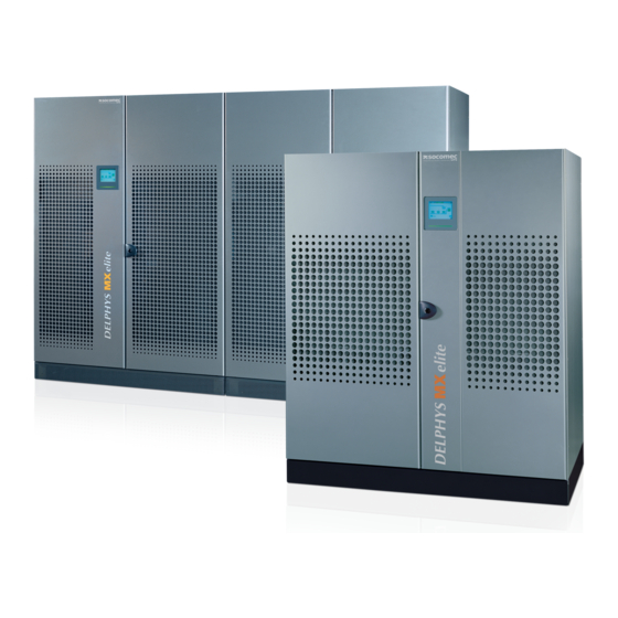
Summary of Contents for socomec DELPHYS MX
- Page 1 DELPHYS MX 2 5 0 t o 9 0 0 k V A...
-
Page 2: Installation Requirements And Protection
OBJECTIVES The aim of these specifications is to provide: • the information required to choose the right uninterruptible power supply for a specific application. • the information required to prepare the system and installation site. The specifications are intended for: • installation engineers. - Page 3 Matrix table for model and kVA power rating DELPHYS MX has been specifically designed to meet the demands of loads in specific application contexts, in order to optimise the features of the product and to facilitate its integration within the system.
- Page 4 [mm] [mm] 1930 1600 1930 1600 DELPHYS MX 250 to 500 kVA 3200 2210 2210 3200 DELPHYS MX 800 and 900 kVA The equipment has been designed with a minimum direct and indirect footprint (the actual space occupied by the unit and the space required around it for maintenance, ventilation and access to the operating mechanisms and communication devices).
-
Page 5: Flexible Backup Time
2.3. Parallel DELPHYS MX UPS units (rectifier, battery, inverter and bypass) can be connected in parallel (up to 6 units) with distributed or central bypass. This solution, which is ideally suited for 1+1 redundancy, offers flexible power upgrading and enables stand-alone UPS units to be expanded. -
Page 6: Electrical Options
3. STANDARD AND OPTIONS 3.1. Standard electrical features. • B ackfeed protection: detection circuit. • S tandard interface: - 3 inputs (emergency stop, generating set, battery protection), - 4 outputs (general alarm, back-up, bypass, preventative maintenance needs). • E BS (Expert Battery System). 3.2. Electrical options. • E BS (Expert Battery System). • FLYWHEEL compatible. -
Page 7: Specifications
4. SPECIFICATIONS 4.1. Installation parameters Installation parameters Rated power (kVA) Phase in/out Active power (kW) Rated/maximum rectifier input current 374/478 453/543 598/705 780/889 1273/1547 1428/1611 (EN 62040-3) (A) Rated bypass input current (A) 1155 1300 Inverter output current @230V (A) P/N 1155 1300 Maximum air flow (m 6140 14600 Sound level (dBA) - Page 8 STANDARD AND OPTIONS Electrical characteristics - Inverter Rated power (kVA) Rated output voltage (selectable) 380/400/415 V Static: < 1% Output voltage tolerance Dynamic: (0-100% Pn) ±2% Rated output frequency 50/60 Hz (selectable) Output frequency tolerance 0.02 on mains power failure Load crest factor (according IEC 62040-3) <...
-
Page 9: Recommended Protection Devices
STANDARD AND OPTIONS 4.3. Recommended protection devices RECOMMENDED PROTECTION DEVICES - Rectifier Rated power (kVA) D curve circuit breaker (A) 1000 1600 RECOMMENDED PROTECTION DEVICES - General bypass Rated power (kVA) Maximum I t supported by the bypass (A 2250000 5120000 Icc max (A) 10600 24700 D curve circuit breaker (A) 1250 1600 RECOMMENDED PROTECTION DEVICES - Input residual current circuit breaker... -
Page 10: Electromagnetic Compatibility
5. REFERENCE STANDARDS AND DIRECTIVES 5.1. Overview The construction of the equipment and choice of materials and components comply with all current laws, decrees, directives and standards currently in force. In particular, the equipment is fully compliant with all European Directives concerning CE marking. 2006/95/EC C ouncil Directive 2006/95/EC, dated 16 February 2007, on the reconciliation of legislation within Member States regarding electrical material for use within specific voltage ranges.


Need help?
Do you have a question about the DELPHYS MX and is the answer not in the manual?
Questions and answers