TESTO Saveris base Instruction Manual
Measurement data monitoring with testo saveris
small business edition
Hide thumbs
Also See for Saveris base:
- Instructions manual (222 pages) ,
- User manual (164 pages) ,
- Instruction manual (94 pages)

Related Manuals for TESTO Saveris base


Summary of Contents for TESTO Saveris base
- Page 1 Measurement data monitoring with testo Saveris Small Business Edition Instruction manual...
-
Page 3: Table Of Contents
First steps ....................29 5.1. Flowchart ..................29 5.2. Inserting SIM card (optional) ............31 5.3. Connecting USB cable to the Saveris base (optional) ....32 5.4. Connecting GSM antenna (optional) ..........33 5.5. Connecting Saveris base with power supply ......... 34 5.5.1. - Page 4 5.11.1.3. Connecting router ................48 5.11.1.4. Assigning probes ................51 5.11.1.5. Connecting routers in series ............53 5.11.2. Assigning an IP address to the Saveris base (optional) ......... 57 5.11.3. Integrating Saveris Ethernet probe (optional) ..........58 5.11.3.1. Connecting the network cable............59 5.11.3.2.
- Page 5 Archiving with automatic reports ..............119 6.8. Checking the database capacity ..........119 6.9. System settings ................121 6.9.1. General settings for the Saveris base ............121 6.9.2. Show operating data of the probes.............. 122 6.9.3. Settings for the radio probe ................123 6.9.4.
- Page 6 7.10.6. Saveris analog coupler ................169 Tips and assistance ................172 8.1. Questions and answers .............. 172 8.2. Saveris base alarm messages ............ 172 8.3. Accessories and spare parts ............173 Pos: 2 /TD/--- Seitenwechsel --- @ 0\mod_1173774430601_0.docx @ 283 @ @ 1...
-
Page 7: Safety And The Environment
2 Safety and the environment Pos: 3 /TD/Überschriften/2. Sicherheit und Umwelt @ 0\mod_1173774719351_79.docx @ 292 @ 1 @ 1 Safety and the environment Pos: 4 /TD/Überschriften/2.1 Zu diesem Dokument @ 0\mod_1173775252351_79.docx @ 346 @ 2 @ 1 2.1. About this document Pos: 5 /TD/Sicherheit und Umwelt/Zu diesem Dokument/Symbole und Schreibkonventionen/Symbole und Schreibkonv. -
Page 8: Ensure Safety
Pos: 8 /TD/Sicherheit und Umwelt/Sicherheit gewährleisten/Saveris Wartungsarbeiten @ 1\mod_1196958627509_79.docx @ 6094 @ @ 1 > Carry out only the maintenance and repair work on the components of the testo Saveris system that is described in the documentation. Follow the prescribed steps exactly. Use only original spare parts from Testo. -
Page 9: Specifications
Specifications Pos: 16 /TD/Überschriften/3.1 Verwendung @ 0\mod_1176211016437_79.docx @ 695 @ 2 @ 1 3.1. Pos: 17 /TD/Leistungsbeschreibung/Verwendung/testo Saveris/01 Einsatzgebiete @ 1\mod_1197376440546_79.docx @ 6184 @ 5 @ 1 Areas of application The testo Saveris measurement system can be used everywhere where temperature and humidity-sensitive products are produced... -
Page 10: System Requirements
With the testo Saveris software you thereby always have an overview of the development of the readings in the individual areas. Pos: 21 /TD/Leistungsbeschreibung/Verwendung/testo Saveris/04 Haftungsausschluss @ 1\mod_1197376616906_79.docx @ 6214 @ 5 @ 1 Exclusion of liability The testo Saveris system was developed to consolidate a large... - Page 11 Pos: 25 /TD/Leistungsbeschreibung/Systemvoraussetzungen/Akku-Info (Saveris) @ 14\mod_1373268824588_79.docx @ 171823 @ 5 @ 4 Rechargeable battery The battery in the Saveris base, the Ethernet probes and the analog coupler is a wearing part, which has to be replaced after approx. 2 years. If a battery is faulty, it is not possible to guarantee full operability of the GSM module.
-
Page 12: Product Description
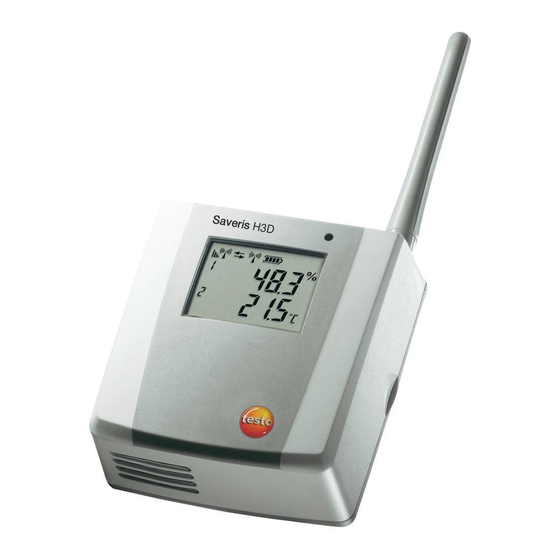
Pos: 28 /TD/Produktbeschreibung/Übersicht/testo Saveris/Hinweis CE @ 1\mod_1204905902234_79.docx @ 12612 @ @ 4 As declared in the declaration of conformity, this product complies with Directive 2014/30/EC. Pos: 29 /TD/Produktbeschreibung/Übersicht/testo Saveris/00 Base/01 Base @ 0\mod_1189504245140_79.docx @ 4274 @ 255 @ 1 4.1. Saveris base Front Display for the visualization of the alarms and user guidance. - Page 13 4 Product description Rear USB cable connection. Network cable connection. Connection of power supply via mains plug. Connection of power supply via 24 V AC/DC and alarm relay. Connection for external GSM antenna (only in combination with GSM module). Eyelets for strain relief. Guide for stand or wall bracket.
-
Page 14: Saveris Base Gsm Module (Optional)
4 Product description Pos: 30 /TD/Produktbeschreibung/Übersicht/testo Saveris/00 Base/02 Base GSM @ 1\mod_1196957066669_79.docx @ 6084 @ 3 @ 1 4.2. Saveris base GSM module (optional) Insertion slot for the SIM card. Pos: 31 /TD/Produktbeschreibung/Übersicht/testo Saveris/00 Base/Bedientasten @ 0\mod_1190205422265_79.docx @ 4893 @ 3 @ 1 4.2.1. -
Page 15: Displays
The netmask is the basic address of the network in which the Saveris base is integrated. Address of the gateway that is saved in the Saveris base. A gateway is a transfer point between networks that work with different protocols or data formats. A "translation" into the respective other protocol or data format is then performed by the gateway. - Page 16 4 Product description Info Alarm menu Number of the newly triggered alarms. Keys that are assigned functions in this menu. New alarms have to be checked and acknowledged at regular intervals. A large number (>100) of unacknowledged alarms will impair the system performance.
- Page 17 4 Product description Keys that are assigned functions in this menu. Reading detail menu Probe and duct, if present, for which the reading was transferred. Reading with corresponding unit. Time at which the reading was transferred. Date on which the reading was transferred. Number of the reading and total number of readings.
- Page 18 4 Product description Telephone number that is saved on the SIM card. Keys that are assigned functions in this menu. Version number of the internal GSM module. Instrument detail menu Serial number of the connected instrument. Firmware version of the connected instrument. Type designation of the connected instrument.
- Page 19 4 Product description Info System menu Number of connected radio probes. Number of connected Ethernet probes. Number of connected routers. Number of connected converters. Keys that are assigned functions in this menu. Login 1/2 menu Status display when probes are connected.
- Page 20 4 Product description Login 2/2 menu Keys that are assigned functions in this menu. This display is shown if no login signal was received from a probe within approx. 30 seconds.
-
Page 21: Save Radio Probe
Pos: 33 /TD/Produktbeschreibung/Übersicht/testo Saveris/01 Funkfühler/00 Funkfühler @ 0\mod_1190281497265_79.docx @ 5041 @ 3 @ 1 4.3. Save radio probe Pos: 34 /TD/Produktbeschreibung/Übersicht/testo Saveris/01 Funkfühler/01 Funkfühler ohne Display @ 0\mod_1189496319546_79.docx @ 4255 @ 3 @ 1 4.3.1. Radio probe without display LED for status display. -
Page 22: Radio Probe With Display
4 Product description Pos: 35 /TD/Produktbeschreibung/Übersicht/testo Saveris/01 Funkfühler/02 Funkfühler mit Display @ 0\mod_1189496687343_79.docx @ 4264 @ 35 @ 1 4.3.2. Radio probe with display Display for showing reading, battery and connection status as well as the field strength of the radio link. -
Page 23: Meaning Of The Led Displays At The Probes
( ) limit value. Number of the channel. Display for a second sensor in the probe. Pos: 36 /TD/Produktbeschreibung/Übersicht/testo Saveris/01 Funkfühler/03 Bedeutung der LED @ 0\mod_1190807440000_79.docx @ 5133 @ 255 @ 1 4.3.3. Meaning of the LED displays at the probes... -
Page 24: Saveris Ethernet Probes
Flashing 3 x red No connection to the Saveris base exists. Pos: 37 /TD/Produktbeschreibung/Übersicht/testo Saveris/02 Ethernet-Fühler/00 Ethernet-Fühler @ 1\mod_1197555728828_79.docx @ 6366 @ 5 @ 1 4.4. Saveris Ethernet probes Pos: 38 /TD/Produktbeschreibung/Übersicht/testo Saveris/02 Ethernet-Fühler/02 Ethernet-Fühler @ 1\mod_1197555730062_79.docx @ 6386 @ 2 @ 1 Display for showing the reading and transmission information. - Page 25 4 Product description Input for power supply via mains unit. Displays Quality of the connection. Battery status. Indicator as to whether a communication with the Saveris base is performed. Unit of the reading: • for humidity measurement • for current measurement •...
-
Page 26: Saveris Router
4 Product description Pos: 39 /TD/Produktbeschreibung/Übersicht/testo Saveris/03 Router/01 Router @ 1\mod_1197555862937_79.docx @ 6406 @ 2 @ 1 4.5. Saveris router Antenna for the radio transmission of the measurement data LED for status display Connect button for connecting the router to the Saveris base... -
Page 27: Saveris Converter
4 Product description Pos: 40 /TD/Produktbeschreibung/Übersicht/testo Saveris/04 Converter/01 Converter @ 1\mod_1197557086312_79.docx @ 6416 @ 2 @ 1 4.6. Saveris converter Antenna for receiving the measurement data. LED for status display. Connect button for connecting the converter to the Saveris base and for a status request during operation. -
Page 28: Saveris Analog Coupler
4 Product description Pos: 41 /TD/Produktbeschreibung/Übersicht/testo Saveris/05 Analogkoppler/01 Analogkoppler @ 4\mod_1245762445743_79.docx @ 45338 @ 2 @ 1 4.7. Saveris analog coupler Only with radio analog coupler U1: Antenna for sending the measurement data. LED for status display. Connect button for connecting the analog coupler to the Saveris base and for a status request during operation. -
Page 29: First Steps
5 First steps Pos: 43 /TD/Überschriften/5. Erste Schritte @ 0\mod_1173774895039_79.docx @ 319 @ 2 @ 1 First steps Pos: 44 /TD/Erste Schritte/testo Saveris/00 Ablaufdiagramm Inbetriebnahme @ 0\mod_1189581707421_79.docx @ 4454 @ 2 @ 1 5.1. Flowchart Start Base with Inserting SIM card... - Page 30 5 First steps Installing software Integrating Ethernet Use Ethernet probe probes? Integrating converter converter? Start up hardware with the help of the startup wizard. Creating zones Performing the test run Configuring the alarms Mounting the hardware Starting software...
-
Page 31: Inserting Sim Card (Optional)
5 First steps Pos: 45 /TD/Erste Schritte/testo Saveris/00 SIM-Karte einsetzen @ 1\mod_1197557316734_79.docx @ 6426 @ 2 @ 1 5.2. Inserting SIM card (optional) With a Saveris base with integrated GSM module, you must insert the SIM card. The SIM card for sending SMS messages is not included in the delivery and must be purchased separately from a mobile phone provider. -
Page 32: Connecting Usb Cable To The Saveris Base (Optional)
5 First steps Pos: 46 /TD/Erste Schritte/testo Saveris/01 USB-Kabel an Base anschließen @ 0\mod_1190210196906_79.docx @ 4930 @ 2 @ 1 5.3. Connecting USB cable to the Saveris base (optional) 1. Loosen and remove screw connection. 2. Remove cover from Saveris Base. -
Page 33: Connecting Gsm Antenna (Optional)
Pos: 49 /TD/Erste Schritte/testo Saveris/01c Antenne anschließen @ 1\mod_1202123742093_79.docx @ 8056 @ @ 1 > Place antenna cable on the coaxial connection and screw Pos: 50 /TD/Erste Schritte/testo Saveris/02 Base mit Stromversorgung verbinden @ 0\mod_1188477940515_79.docx @ 2955 @ 3 @ 1... -
Page 34: Connecting Saveris Base With Power Supply
You can connect the Saveris base to the power supply via the included mains unit or via the 24 V AC/DC plug-in/screw terminal. Pos: 51 /TD/Erste Schritte/testo Saveris/02a-1 Stromversorgung über Netzteil verbinden @ 0\mod_1191328326843_79.docx @ 5392 @ 3 @ 1 5.5.1. -
Page 35: Power Supply Via Plug-In/Screw Connection (Optional)
5 First steps Pos: 54 /TD/Erste Schritte/testo Saveris/02b-1 Stromversorgung über AC/DC verbinden @ 0\mod_1191328406187_79.docx @ 5402 @ 3 @ 1 5.5.2. Power supply via plug-in/screw connection (optional) Pos: 55 /TD/Erste Schritte/testo Saveris/02b-2 SBE Stromversorgung über AC/DC verbinden @ 1\mod_1202124389613_79.docx @ 8067 @ @ 1 Pos: 56 /TD/Erste Schritte/testo Saveris/02b-3 Stromversorgung über AC/DC verbinden @ 1\mod_1202124473316_79.docx @ 8089 @ @ 1... -
Page 36: Inserting Batteries In The Probes
5 First steps Pos: 57 /TD/Erste Schritte/testo Saveris/02 b Batterien am Fühler einlegen @ 0\mod_1191322124515_79.docx @ 5263 @ 2 @ 1 5.6. Inserting batteries in the probes 1. Loosen screws on the rear of the probe. 2. Remove housing cover of probe 3. -
Page 37: Connecting Radio Probe
5 First steps Pos: 58 /TD/Erste Schritte/testo Saveris/03 Fühler an der Base anmelden @ 0\mod_1188478029328_79.docx @ 2964 @ 2 @ 1 5.7. Connecting radio probe You can connect a maximum of 15 probes to the Saveris base directly via radio. - Page 38 Multiple probes cannot be connected at the Saveris base simultaneously. Multiple probes can only be connected one after the other. 4. At the Saveris base, press the • [Esc] key if no more components are to be connected.
-
Page 39: Installing Saveris Software
Saveris base; see Integrating a Saveris router (optional), page 44. Pos: 59 /TD/Erste Schritte/testo Saveris Inbetriebnahme/05a Saveris-Software installieren @ 1\mod_1199789424718_79.docx @ 6964 @ 2 @ 1 5.8. Installing Saveris software >... -
Page 40: Starting Up Hardware
• measurement operation has been ended. 1. Connect the Saveris base via the USB or network cable to the computer on which the Saveris client is installed. For continuous operation of the system, it is recommended that the Saveris base be connected to the computer via an Ethernet cable. - Page 41 • Mark an existing project and click on [OK] to adopt the configuration data of the marked project for the new project. The system settings of the Saveris base that are based on the marked project are shown.
-
Page 42: Starting Saveris Software
6. Click on [OK]. 7. Make any further changes to the existing system settings as required (see installation instructions). Pos: 61 /TD/Produkt verwenden/testo Saveris/01 Start/01_Saveris-Software starten @ 0\mod_1189076832593_79.docx @ 3933 @ 2 @ 4 5.10. Starting Saveris software Ensure that the Saveris software is not already open, ®... - Page 43 3. Select the project that is to be opened in the tree structure. 4. Confirm with [OK]. Testo Saveris software program window is shown with the selected data record in the foreground. Pos: 62 /TD/Erste Schritte/testo Saveris/Hardware erweitern/Messsystem erweitern @ 1\mod_1197551581796_79.docx @ 6327 @ 3 @ 1...
-
Page 44: Expand Measuring System
In this chapter, you learn how to integrate the Saveris router, converter, Ethernet probes and analog coupler into the measuring system. Pos: 63 /TD/Erste Schritte/testo Saveris/Hardware erweitern/01 a Router einbinden/00 Router einsetzen @ 1\mod_1197549116203_79.docx @ 6304 @ 4 @ 1 5.11.1. Integrating a Saveris router (optional) You can use a Saveris router to optimize radio communication under poor structural conditions or to extend the radio path. -
Page 45: Connecting Router With Power Supply (Mains Unit)
5 First steps Pos: 64 /TD/Erste Schritte/testo Saveris/Hardware erweitern/01 a Router einbinden/01 Router-Strom @ 1\mod_1197548324640_79.docx @ 6294 @ 4 @ 1 5.11.1.1. Connecting router with power supply (mains unit) 1. Open cover 2. Insert mains cable 3. Insert mains plug into a socket. -
Page 46: Connecting Router With Power Supply (Ac/Dc)
5 First steps Pos: 65 /TD/Erste Schritte/testo Saveris/Hardware erweitern/01 a Router einbinden/01b Router-ACDC @ 1\mod_1197978273593_79.docx @ 6543 @ 4 @ 1 5.11.1.2. Connecting router with power supply (AC/DC) 1 Remove protection caps 2. Loosen screws on the rear of the router. - Page 47 5 First steps 5. Loosen clamping screws 6. Route cabling through the cable opening and insert in the terminals It is not necessary to note the polarity. 7. Tighten clamping screws.
-
Page 48: Connecting Router
The wall mounting of a router is performed in the same ways as for a probe; see "Mounting the probe on the wall". Pos: 66 /TD/Erste Schritte/testo Saveris/Hardware erweitern/01 a Router einbinden/02 Router anmelden @ 1\mod_1197548238578_79.docx @ 6274 @ 4 @ 1 5.11.1.3. Connecting router You can connect a maximum of 30 routers to the Saveris base. - Page 49 1. Change to the Info System menu at the Saveris base with the [▼] button. 2. Press [Enter] to call up the Login function. The status bar in the display shows that the Saveris base is ready for router detection.
- Page 50 • Press [Enter] if further components are to be connected; see previous step. Pos: 67 /TD/Erste Schritte/testo Saveris/Hardware erweitern/01 a Router einbinden/03 Fühler zuweisen @ 1\mod_1197548250906_79.docx @ 6284 @ 4 @ 1...
-
Page 51: Assigning Probes
5 First steps 5.11.1.4. Assigning probes To assign a probe to a router, both must be connected in the Saveris base. 1. Under Start All Programs Testo click on Saveris Startup Wizard. The welcome dialogue of the startup assistant is shown. - Page 52 > Perform steps 4 to 5 for all remaining probes whose measurement data is to be transmitted to the Saveris base via a router. 6. Position the probes and router at their mounting locations to check the radio links.
-
Page 53: Connecting Routers In Series
If you want to use probes in a router cascade, see Starting up Ethernet probes, page 65 see Connecting routers in series, page 53 Pos: 68 /TD/Erste Schritte/testo Saveris/Hardware erweitern/01 a Router einbinden/04 Router hinteinanderschalten @ 8\mod_1295275223441_79.docx @ 75773 @ 3 @ 1 5.11.1.5. Connecting routers in series Max. - Page 54 5 First steps 2. Click on [Next >]. System status dialogue box is displayed with the tab General.
- Page 55 5 First steps 3. Switch to the Router tab. 4. Click on [Cascade routers]. Cascade routers window is opened. 5. Select routers in the order in which they should be connected in series starting at the base (from left to right).
- Page 56 8. Place the routers in their installation locations to check the radio connections. 9. Briefly press Connect on the back of the router that is next in the series after the Saveris base (router 1 in the diagram). If the LED on the front of the router flashes •...
-
Page 57: Assigning An Ip Address To The Saveris Base (Optional)
5 First steps Pos: 69 /TD/Erste Schritte/testo Saveris/Hardware erweitern/01 b IP-Adresse der Base zuweisen @ 12\mod_1338376877611_79.docx @ 125816 @ 3 @ 1 5.11.2. Assigning an IP address to the Saveris base (optional) If an Ethernet probe, converter and/or extender is integrated into the Saveris system, a static IP address should first be assigned for the Saveris base. -
Page 58: Integrating Saveris Ethernet Probe (Optional)
5. Follow the wizard's instructions and assign the IP address for the Saveris base. see Installing Saveris software, page 39 Pos: 70 /TD/Erste Schritte/testo Saveris/Hardware erweitern/03 Ethernet-Fühler einbinden/00 Ethernet-Fühler einsetzen @ 1\mod_1197552336953_79.docx @ 6336 @ 4 @ 1 5.11.3. Integrating Saveris Ethernet probe (optional) In addition to the Saveris radio probes, you can use probes that are connected to the Ethernet interface of the Saveris base. -
Page 59: Connecting The Network Cable
In this context, note that a maximum of 150 probes can be connected or 450 measurement channels recorded at the Saveris base. Pos: 71 /TD/Erste Schritte/testo Saveris/Hardware erweitern/03 Ethernet-Fühler einbinden/01 Netzwerkkabel @ 1\mod_1203421433000_79.docx @ 8193 @ 4 @ 1 5.11.3.1. Connecting the network cable. -
Page 60: Connecting Ethernet Probe With Power Supply (Mains Unit)
You can connect the probe to the network via a network hub or directly at the Saveris base via the Ethernet jack. Pos: 72 /TD/Erste Schritte/testo Saveris/Hardware erweitern/03 Ethernet-Fühler einbinden/01c Stromversorgung @ 1\mod_1203423817781_79.docx @ 8270 @ 4 @ 1 5.11.3.2. -
Page 61: Connecting Usb Cable And Installing Driver (Optional)
2. Insert mains cable 3. Insert mains plug into a socket. Pos: 73 /TD/Erste Schritte/testo Saveris/Hardware erweitern/03 Ethernet-Fühler einbinden/01b USB-Kabel @ 1\mod_1203423817203_79.docx @ 8259 @ 4 @ 1 5.11.3.3. Connecting USB cable and installing driver (optional) 1. -
Page 62: Assigning Connection Data
5 First steps Pos: 74 /TD/Erste Schritte/testo Saveris/Hardware erweitern/03 Ethernet-Fühler einbinden/03 Verbindungsdaten zuweisen @ 1\mod_1203421515781_79.docx @ 8226 @ 4 @ 1 5.11.3.4. Assigning connection data You must now enter the connection settings for the Ethernet probes. 1. Open the wizard for entering the connection settings via... - Page 63 Ethernet probes in the display of the base is increased by 1; see Displays, page 15. Pos: 75 /TD/Erste Schritte/testo Saveris/Hardware erweitern/03 Ethernet-Fühler einbinden/04 Netzwerkkabel an Base anschließen @ 1\mod_1203430798656_79.docx @ 8313 @ 4 @ 1...
-
Page 64: Connecting The Network Cable To The Saveris Base
1. Loosen and remove screw connection. 2. Remove cover from Saveris Base. 3. Plug the network cable into the Saveris base. Pos: 76 /TD/Erste Schritte/testo Saveris/Hardware erweitern/03 Ethernet-Fühler einbinden/05 Ethernet-Fühler inbetrieb nehmen @ 1\mod_1203421551984_79.docx @ 8237 @ 3 @ 1... -
Page 65: Starting Up Ethernet Probes
5 First steps 5.11.3.6. Starting up Ethernet probes 1. Via Start All Programs Testo Startup Wizard, start the wizard to start up new hardware components. The wizard opens with the welcome screen. 2. Click on [Next >]. Commission new probe... - Page 66 5 First steps 3. Leave default setting and click on [Next >]. The list of probes newly registered in the Saveris base is displayed.
- Page 67 5 First steps 4. Click on [Add stationary zone]. 5. Open the selection list via button and select the zone to which the probe should be assigned. 6. Click on [Next >]. 7. Click in the TE type field and enter the thermocouple element type (K, J, or S) if this information is necessary for the device.
- Page 68 5 First steps 11. Enter Measuring cycle and define its Unit. The measuring cycle determines the intervals at which a new measured value is saved in the Saveris base. Possible settings for the unit: • (second) • (minute) • (hour).
-
Page 69: Integrating Saveris Converter (Optional)
15. Confirm the message by clicking [OK]. The new hardware is now ready to be used. Pos: 77 /TD/Erste Schritte/testo Saveris/Hardware erweitern/02 Converter einbinden/00 Converter einsetzen @ 1\mod_1197550607093_79.docx @ 6315 @ 35 @ 1 5.11.4. Integrating Saveris converter (optional) -
Page 70: Integrating Saveris Analog Coupler (Optional)
The probe/router is connected at the converter and this transmits the measurement data to the Saveris base. Pos: 78 /TD/Erste Schritte/testo Saveris/Hardware erweitern/04 Analogkoppler einbinden/00 Analogkoppler einsetzen @ 4\mod_1248880773887_79.docx @ 46514 @ 2555 @ 1 5.11.5. Integrating Saveris analog coupler (optional) - Page 71 5 First steps Parameterizing analog coupler with Startup Wizard 1. Under Start All Programs Testo click on Testo Saveris Startup Wizard. The welcome dialogue of the startup wizard is shown. 2. Click on [Next >]. Commission new probe dialogue is shown.
- Page 72 5 First steps 3. Leave default setting and click on [Next >]. Analog couplers can always only be additionally included in the configuration and cannot be used as a replacement for ones that are already present. Scale dialogue is displayed.
- Page 73 7. Select number of Decimal places. 8. Click on [Set up sum channel] if the summation of a particular unit is required. 9. Click on [Next >]. The list of the probes newly registered in the Saveris base is shown.
- Page 74 5 First steps 10. Click on [New stationary zone]. 11. Open the selection list via button and select the zone to which the probe should be assigned. 12. Click on [Next >]. 13. Click in the TE type field and enter the thermocouple element type (K, J, or S) if this information is necessary for the device.
- Page 75 • (minute) • (hour). 18. Click on [Next > If a router is registered on the Saveris base, the configuration of the connection type for the probes is shown. If you have not registered a router, continue with step 24.
- Page 76 Probes in a mobile zone cannot be assigned to a router. 21. Perform steps 21 and 22 for any other probes with measurement data to be transmitted to the Saveris base via a router. 22. Click on [Next >].
-
Page 77: Performing The Test Run
25. Confirm the message by clicking [OK]. The new hardware is now ready to be used. Pos: 79 /TD/Erste Schritte/testo Saveris/06 ****Probelauf/00 Probelauf und Abnahme durchführen @ 0\mod_1189157354187_79.docx @ 4054 @ 3 @ 1 5.12. Performing the test run The test run must be performed to ensure proper operation of the measuring system. -
Page 78: Testing The System
The LED at the probe shows the connection status; also see "Meaning of the LED displays at the probes " for this. Pos: 81 /TD/Erste Schritte/testo Saveris/06 ****Probelauf/Systemtest durchführen @ 10\mod_1321361553028_79.docx @ 103136 @ 3 @ 1 5.12.2. Testing the system For a simple system test: •... -
Page 79: Checking Alarm Chain
[SMS test report] button. A test report is sent to the mobile phone number entered. Pos: 84 /TD/Erste Schritte/testo Saveris/07 **** Montage der Hardware/00 Hardware montieren @ 0\mod_1189157579984_79.docx @ 4124 @ 3 @ 1 5.13. Mounting the hardware The notes in chapter "Ensure safety" must absolutely be observed when mounting the Saveris components. -
Page 80: Mounting The Saveris Base On The Wall
5 First steps Pos: 85 /TD/Erste Schritte/testo Saveris/07 **** Montage der Hardware/01 Base an der Wand montieren @ 0\mod_1189157492531_79.docx @ 4105 @ 3 @ 1 5.13.1. Mounting the Saveris base on the wall When selecting the location for the Saveris base,... - Page 81 5 First steps 5. Place Saveris base on the wall bracket and secure with screw Pos: 86 /TD/Erste Schritte/testo Saveris/07 **** Montage der Hardware/01b Base mit Standfuß @ 0\mod_1190975629546_79.docx @ 5233 @ 3 @ 1...
-
Page 82: Setting Up Saveris Base With Stand
The Saveris base must be positioned close enough to the computer used and a possible power supply in accordance with the cabling provided. 1. Place the Saveris base on the stand 2. Set up the Saveris base at the desired location. -
Page 83: Mounting The Probe On The Wall
5 First steps Pos: 87 /TD/Erste Schritte/testo Saveris/07 **** Montage der Hardware/03 Fühler montieren @ 0\mod_1189157541812_79.docx @ 4114 @ 3 @ 1 5.13.3. Mounting the probe on the wall When selecting the location, take into account the following points: •... -
Page 84: Checking The Measuring System Again
Please refer to "Removing probe from wall bracket" for removing the probe from the wall bracket. Pos: 88 /TD/Erste Schritte/testo Saveris/07 **** Montage der Hardware/04 System prüfen @ 0\mod_1191327191562_79.docx @ 5362 @ 3 @ 1 5.13.4. Checking the measuring system again >... -
Page 85: Using The Product
Pos: 89 /TD/--- Seitenwechsel --- @ 0\mod_1173774430601_0.docx @ 283 @ @ 1 Pos: 90 /TD/Überschriften/6. Produkt verwenden @ 0\mod_1173774928554_79.docx @ 328 @ 2 @ 1 Using the product Pos: 91 /TD/Produkt verwenden/testo Saveris/01 Start/02_Bedienoberfläche_01 @ 0\mod_1189076833359_79.docx @ 3943 @ 2 @ 1 6.1. User interface In this chapter, you learn how the user interface of the Saveris software is designed. - Page 86 Pos: 98 /TD/Produkt verwenden/testo Saveris/01 Start/02_Bedienoberfläche_08 @ 1\mod_1197984029171_79.docx @ 6663 @ @ 1 Status bar Shows the status information for the software. Pos: 99 /TD/Produkt verwenden/testo Saveris/02 Menüs und Befehle der Ribbon-Leiste/00 Menüs und Befehle @ 0\mod_1190279903078_79.docx @ 4975 @ 3 @ 1...
-
Page 87: Menus And Commands
In this chapter, you learn which menus and commands are available to you and what you can use these commands for. Pos: 100 /TD/Produkt verwenden/testo Saveris/02 Menüs und Befehle der Ribbon-Leiste/01 Start/00 Menü Start @ 0\mod_1190280034765_79.docx @ 4984 @ 5 @ 1 6.2.1. -
Page 88: Edit
Pos: 107 /TD/Produkt verwenden/testo Saveris/02 Menüs und Befehle der Ribbon-Leiste/02 Bearbeiten/00 Menü Bearbeiten @ 0\mod_1190280106796_79.docx @ 4993 @ 5 @ 1 6.2.2. Edit Pos: 108 /TD/Produkt verwenden/testo Saveris/02 Menüs und Befehle der Ribbon-Leiste/02 Bearbeiten/02 Bearbeiten (Diagramm) @ 0\mod_1189606502281_79.docx @ 4555 @ 3 @ 1... - Page 89 Scaling of the value axis. Edit Time axis (diagram) menu Menu Description function Grid Scaling of the time axis. Pos: 109 /TD/Produkt verwenden/testo Saveris/02 Menüs und Befehle der Ribbon-Leiste/02 Bearbeiten/03 Bearbeiten (Tabelle)_SBE @ 0\mod_1189606537468_79.docx @ 4565 @ 35 @ 1...
-
Page 90: Options
Maximum Shows the largest reading of the selected channel within the table. Pos: 110 /TD/Produkt verwenden/testo Saveris/02 Menüs und Befehle der Ribbon-Leiste/03 Extras/00 Menü Extras @ 0\mod_1190280173640_79.docx @ 5003 @ 3 @ 1 6.2.3. Options Pos: 111 /TD/Produkt verwenden/testo Saveris/02 Menüs und Befehle der Ribbon-Leiste/03 Extras/01 Verwaltung @ 1\mod_1197373808453_79.docx @ 6173 @ @ 1... - Page 91 Opens the dialogue box for setting the settings automatic protection. For security reasons, backup files should be saved on a different PC to the Saveris database. Pos: 112 /TD/Produkt verwenden/testo Saveris/02 Menüs und Befehle der Ribbon-Leiste/03 Extras/02 Bearbeiten @ 0\mod_1189606801796_79.docx @ 4596 @ @ 1...
- Page 92 With Set as preference, these settings are saved here. Delete preferences resets the settings. Pos: 113 /TD/Produkt verwenden/testo Saveris/02 Menüs und Befehle der Ribbon-Leiste/03 Extras/04 Schriftart @ 0\mod_1189606719546_79.docx @ 4576 @ 3 @ 1 Extras Font menu Menu Description function Font Setting the font for the tables and diagrams.
-
Page 93: Axes
Create new Enables the creation of a new template. template Pos: 119 /TD/Produkt verwenden/testo Saveris/02 Menüs und Befehle der Ribbon-Leiste/06 Menü Projekt auswählen @ 3\mod_1233571007869_79.docx @ 23692 @ 3 @ 1 6.2.6. Selecting projects The project data for all projects already created can be displayed using the selection menu without having to restart the software. -
Page 94: Creating, Editing And Deleting Zones
6 Using the product Pos: 121 /TD/Produkt verwenden/testo Saveris/03 Gruppen einrichten/organisieren/00 Zonen anlegen und löschen @ 0\mod_1190280348609_79.docx @ 5023 @ 2 @ 1 6.3. Creating, editing and deleting zones After you have familiarized yourself with the menus of the Saveris software, you can now turn to creating zones, for example to separate the probes according to location. -
Page 95: Change Zones
6 Using the product Pos: 123 /TD/Produkt verwenden/testo Saveris/03 Gruppen einrichten/organisieren/06 Zonen ändern @ 0\mod_1189667459468_79.docx @ 4733 @ 3 @ 1 6.3.2. Change zones You can add channels to an existing zone. You can delete channels that you no longer require in a zone from this zone. You can also change the name of the zone. -
Page 96: Basic Settings For The Sms Messages
Several hundred unacknowledged alarms not only make troubleshooting in serious cases more difficult, but also slow the system response during operation. Pos: 126 /TD/Produkt verwenden/testo Saveris/04 Alarme konfigurieren/01 Alarm vorkonfigurieren @ 0\mod_1188997882750_79.docx @ 3781 @ 3 @ 1 6.4.1. Basic settings for the SMS messages... - Page 97 Saveris base is equipped with a GSM module. 3. Perform the required settings. When exiting the basic settings the settings are saved. Pos: 127 /TD/Produkt verwenden/testo Saveris/04 Alarme konfigurieren/SBE/01 Alarm vorkonfigurieren - 00 Alarme der Base einrichten SBE @ 12\mod_1338533178190_79.docx @ 126729 @ 3 @ 1...
-
Page 98: Setting Up Base Alarms
Display Explanation Device alarm Setting options for the base alarms Saveris Base Missing PC connection: no response from the PC Memory almost full: alarm when the base memory overflows. No GSM network: alarm when there is no GSM connection. -
Page 99: Setting Up Alarm Groups
Entries. 5. Exit Alarm Management menu. Alarm settings are transferred to the devices. Pos: 128 /TD/Produkt verwenden/testo Saveris/04 Alarme konfigurieren/SBE/01 Alarm vorkonfigurieren - 01 Gruppen SBE @ 15\mod_1381828452982_79.docx @ 178253 @ 3455555455555 @ 1 6.4.3. Setting up alarm groups 6.4.3.1. - Page 100 LoBat and power failure Alarm conditions: trigger acknowledged alarms after [min] Alarm output Saveris Base: settings for relays, audible signal and light signal. [Apply entries] Saves the alarm settings of an alarm group.
-
Page 101: Channels
6 Using the product Creating a new group 1. Right-click on component, then click on [Insert into new group]. A new alarm group is created. 2. Overwrite the default names in Group alarm settings. Move to… 1. Right-click on component, then click on [Move to …]. - Page 102 6 Using the product Designation Description [Insert into new Creates a new alarm group, with group] a distinction between alarm, warning and trend alarm group. A trend alarm is used to monitor temporal changes or the stability of measurement parameters. The change in the measurement parameter is determined over four measurement cycles and...
- Page 103 Alarm conditions: settings for lower limit delay [Measurements], upper limit delay [Measurements] and trigger acknowledged alarms after [min] Alarm output Saveris Base: settings for relays, audible signal and light signal. [Apply entries] Saves the alarm settings of an alarm group.
-
Page 104: Analyzing Series Of Measurements
Activate Table if the data is to be displayed in tabular form. Pos: 130 /TD/Produkt verwenden/testo Saveris/05a Diagramme analysieren/00 Diagramme @ 0\mod_1188996581406_79.docx @ 3484 @ 3 @ 1 6.5.1. Diagram view In this view, the readings are shown as line diagrams. -
Page 105: Showing Regression Curve
In doing this, it is not necessary to exactly follow the course of the curve; the crosshairs does this automatically if you move the mouse to the right or left. Pos: 133 /TD/Produkt verwenden/testo Saveris/05a Diagramme analysieren/04 Ausgleichskurve @ 0\mod_1188996582968_79.docx @ 3524 @ 4 @ 1 6.5.1.3. Showing regression curve Place the regression curve over the diagram to show the course that the measurement series tends to take. -
Page 106: Characteristics Of A Curve
6 Using the product Delete text field 1. Click on the text field and remove all the contents. The text field is deleted. 6.5.1.5. Characteristics of a curve You can adapt the representation of a measurement series to your requirements. For example, you can change the line weight of a curve or the representation of the limit values in the diagram. - Page 107 6 Using the product Pos: 135 /TD/Produkt verwenden/testo Saveris/05a-2 Kurveneigenschaften/01 Register Kurve bearbeiten @ 0\mod_1188996705609_79.docx @ 3666 @ 5 @ 1 Curve Designation Explanation Smooth The measurement points are connected by an interpolated curve; the plot-points on the curve between two measurement points are estimated mathematically.
- Page 108 "1" degree of regression the linear trend, a higher value helps in the event of curves with several extreme values. Pos: 136 /TD/Produkt verwenden/testo Saveris/05a-2 Kurveneigenschaften/02 Register Grenzwertanzeige @ 0\mod_1188996705265_79.docx @ 3656 @ 5 @ 1 Range limits Designation Explanation...
- Page 109 Undershoot Colour selection for the fill of the area below the lower limit value. Pos: 137 /TD/Produkt verwenden/testo Saveris/05a-2 Kurveneigenschaften/04 Register Stat. Berechnung @ 0\mod_1188996705906_79.docx @ 3676 @ 5 @ 1 Statistical computation Designation Explanation Min.
-
Page 110: Settings For The Axes In The Diagram
Recalculate Recalculates the curve. Pos: 138 /TD/Produkt verwenden/testo Saveris/05a-3 Achseinstellungen/05 Einstellungen für die Achsen im Diagramm @ 0\mod_1193999542168_79.docx @ 5684 @ 4 @ 1 6.5.1.6. Settings for the axes in the diagram Change the settings of the axes in the diagram to adapt the representation to your requirements. - Page 111 Manual entry of the grid. division is activated) Pos: 140 /TD/Produkt verwenden/testo Saveris/05a-3 Achseinstellungen/07 Zeitachse @ 0\mod_1193999544199_79.docx @ 5704 @ 5 @ 1 Settings for the time axis > With the right mouse button, click on the time axis in the diagram.
- Page 112 6 Using the product Designation Explanation [OK] Applies the settings until other data are called up. The dialogue is closed. [Cancel] Closes the dialogue without applying any changes. Position Shows a freely-definable extract of the diagram. Autom. scaling... Shows the entire diagram in the window. Extract Shows a fixed, defined extract that can be moved over the time axis.
-
Page 113: Marking Readings
The table view of the selected data is shown. > If necessary, deactivate channels via the checkboxes for the display. Pos: 142 /TD/Produkt verwenden/testo Saveris/05b Tabellen analysieren/01 Messwerte markieren @ 0\mod_1188996635625_79.docx @ 3565 @ 4 @ 1 6.5.2.1. Marking readings Mark specific readings to perform a statistical computation for part of the measurement series, for example. -
Page 114: Dropping The Marking
Drop marking. The marking of the readings is deleted. Pos: 144 /TD/Produkt verwenden/testo Saveris/05b Tabellen analysieren/03 Extremwert oder Mittelwert einfügen @ 0\mod_1188996637890_79.docx @ 3585 @ 4 @ 1 6.5.2.3. Inserting extreme values or mean in the table Insert the minimum/maximum reading as well as the mean from the whole table at the end of the table. -
Page 115: Dropping Compression
• (day). 3. Click on [OK]. The dialogue is closed and the table is shown compressed. Pos: 146 /TD/Produkt verwenden/testo Saveris/05b Tabellen analysieren/05 Verdichtung aufheben @ 0\mod_1188996639140_79.docx @ 3605 @ 4 @ 1 6.5.2.5. Dropping compression > Click on Edit... -
Page 116: Compress
Drop compression menu. The table is displayed with all the individual values once again. Pos: 149 /TD/Produkt verwenden/testo Saveris/06c Alarme analysieren/00 Alarme analysieren @ 0\mod_1189079097312_79.docx @ 3954 @ 2 @ 1 6.6. Analyzing alarms If system or probe alarms were triggered by the Saveris base, you can check the alarms and subsequently confirm (acknowledge) them. -
Page 117: Acknowledge The Alarm
Comments on an alarm in the column of the same name. Pos: 151 /TD/Produkt verwenden/testo Saveris/06c Alarme analysieren/02 Alarm quittieren @ 0\mod_1189079436328_79.docx @ 3973 @ 3 @ 1 6.6.2. Acknowledge the alarm If you acknowledge an alarm at the Saveris base, this is carried over into the software. -
Page 118: Creating Evaluations
As soon as the confirmation is received in the Saveris base, the alarm relay stops flashing and the alarm is deleted. Pos: 152 /TD/Produkt verwenden/testo Saveris/07 Berichte/00 Berichte erstellen SBE @ 0\mod_1190280535671_79.docx @ 5032 @ 2 @ 1 6.7. Creating evaluations You can print out series of measurements or have reports on the data automatically created by the software in definable intervals. -
Page 119: Archiving With Automatic Reports
The reports are saved as PDF files so that they can easily be read or sent per e-mail but without being able to change the data stock. Pos: 155 /TD/Produkt verwenden/testo Saveris/07 Berichte/03 ** Langzeitarchivierung und Datensicherung @ 0\mod_1190970854000_79.docx @ 5223 @ 3 @ 1 6.8. - Page 120 A notification is displayed for you to confirm the reset of the Saveris base to the basic configuration. 5. Select whether the system components should be logged out from the Saveris base or remain logged on. The project is completed in the Saveris software.
-
Page 121: System Settings
To start a new project, you must register all components on the Saveris base again and then restart the hardware. Pos: 156 /TD/Produkt verwenden/testo Saveris/09 Einstellungen System/00 Einstellungen System @ 0\mod_1189493729343_79.docx @ 4233 @ 3 @ 1 6.9. System settings In this menu, determine the settings for the Saveris base, the radio probes and –... -
Page 122: Show Operating Data Of The Probes
Saveris base. Date and time Date and time of the Saveris base. Pos: 158 /TD/Produkt verwenden/testo Saveris/09 Einstellungen System/03 Betriebsdaten @ 1\mod_1197536994375_79.docx @ 6253 @ 3 @ 1 6.9.2. Show operating data of the probes. Using this menu item, you can check when the last data were received from a probe, for example, and the duration until the next readings can be expected. -
Page 123: Settings For The Radio Probe
6 Using the product Pos: 159 /TD/Produkt verwenden/testo Saveris/09 Einstellungen System/03 Wireless probes @ 0\mod_1189598701171_79.docx @ 4463 @ 3 @ 1 6.9.3. Settings for the radio probe Using this menu item you can, for example, check the battery status of the probe or the quality of the radio transmission. - Page 124 6 Using the product Designation Explanation Serial number Serial number of the probe. SN humidity Serial number of the connected external module humidity probe. The serial number of the humidity probe that was connected at the time of the connection of the humidity probe to the base is shown.
-
Page 125: Ethernet Probes
Pos: 160 /TD/Produkt verwenden/testo Saveris/09 Einstellungen System/04 Ethernet probes @ 0\mod_1190896768531_79.docx @ 5172 @ 3 @ 1 6.9.4. Ethernet probes Using this menu item, you can check the version of the instrument software of an Ethernet probe, for example. - Page 126 6 Using the product Designation Explanation Serial number Serial number of the probe. SN humidity Serial number of the connected external module humidity probe. The serial number of the humidity probe that was connected at the time of the connection of the Ethernet probe to the base is shown.
-
Page 127: Analog Coupler
Pos: 161 /TD/Produkt verwenden/testo Saveris/09 Einstellungen System/07 Analogkoppler @ 4\mod_1248704611882_79.docx @ 46423 @ 2 @ 1 6.9.5. Analog coupler Via this menu item you can change the power supply of the analog coupler or reset a sum channel, for example. -
Page 128: Report Settings
Button for resetting the sum channel. The channel] sum channel is reset to 0.00. Pos: 162 /TD/Produkt verwenden/testo Saveris/10 Einstellungen Berichte/00 Einstellungen Berichte @ 0\mod_1189494078218_79.docx @ 4243 @ 2 @ 1 6.10. Report settings In the report settings, you can determine how the automatic reporting should take place. - Page 129 6 Using the product Designation Explanation Group box Content When option is enabled, the corresponding data sheet is attached to the report • Detailed • Compact • Brief • Custom • Insert logo • Insert signature line Timing of the report Specify whether the report is to be generation generated daily,...
- Page 130 6 Using the product Designation Explanation Create report Creates a report, thus testing the configured report functions. Apply settings Saves the report configurations. The storage location for the reports was determined during the installation of the Saveris software. The path specification is shown below the Determine folder field.
-
Page 131: Maintaining The Product
Testing the system, page 78. Pos: 167 /TD/Produkt instand halten/testo Saveris/00 Ersatz von Komponenten @ 0\mod_1188476464890_79.docx @ 2909 @ 2 @ 1 7.2. Replacement of components You can shut down a component – probe, converter or router – at any time because this is temporarily not in use or to replace it with a new component, for example, in the event of a defect. - Page 132 7 Maintaining the product 2. Click on [Continue >]. System status dialogue with the General tab is shown.
- Page 133 7 Maintaining the product 3. Change to Projects tab. 4. Click on [De-register component]. De-register component dialogue is shown. 5. Activate the checkbox in front of the component that is to be de- registered from the system. Before deleting a router, you should assign the relevant assigned probes directly to the base to ensure data availability.
-
Page 134: Adding New Components
> After deleting a probe, briefly press the Connect button on the rear of the probe so that the probe no longer attempts to send measurement data. Pos: 169 /TD/Produkt instand halten/testo Saveris/02 Komponenten hinzufügen @ 11\mod_1325774414329_79.docx @ 103843 @ 3 @ 1 7.2.2. Adding new components... - Page 135 7 Maintaining the product 4. Leave default setting and click on [Next >]. The list of probes newly registered in the Saveris base is displayed.
- Page 136 The settings for the measuring cycle are displayed. 12. Enter Measuring cycle and define its Unit. The measuring cycle determines the intervals at which a new measured value is saved in the Saveris base. Possible settings for the unit: • (second) •...
- Page 137 13. Click on [Next >]. If a router is connected at the Saveris base the configuration of the connection type for the probes is shown. If you have not registered a router, continue with step 17. 14. Click in the...
-
Page 138: Logging Components Back In
20. Confirm the message by clicking [OK]. The new hardware is now ready to be used. Pos: 170 /TD/Produkt instand halten/testo Saveris/Komponenten erneut anmelden @ 12\mod_1338382604983_79.docx @ 125984 @ 2 @ 1 7.2.3. Logging components back in When logging components already logged into the current... - Page 139 7 Maintaining the product 3. Click on [Next >]. The software automatically detects whether the probe was already logged in and opens the Commission New Probe dialogue box. 4. In the Connect [To] column, select if the probe measuring values should be updated in the existing data column or [Off] should be selected if the probe measuring values should be displayed in a separate data column.
-
Page 140: Calibration And Adjustment
Note Further configuration is carried out in the same way Add New Component, see Adding new components, page 134. Pos: 171 /TD/Produkt instand halten/testo Saveris/Kalibrierung und Justage @ 0\mod_1188476360640_79.docx @ 2882 @ 25555 @ 1 7.3. Calibration and adjustment Calibration The comparison of a measured value with the correct value under specified conditions. -
Page 141: On-Site Calibration And Adjustment
7 Maintaining the product All testo Saveris probes are adjusted in the factory, which is confirmed by the corresponding adjustment report. Calibration certificates can be ordered separately, see Accessories and spare parts page 173. For consistently reliable data, we recommend carrying out probe calibration and any necessary adjustment at regular intervals, e.g. -
Page 142: Saving Data In The Saveris Base
9. Press the connect key on both probes, one after the other. Replacement is now complete (measurement data is supplied to the system via the original probe once again). Pos: 172 /TD/Produkt instand halten/testo Saveris/Base sichern @ 0\mod_1189416604765_79.docx @ 4183 @ 2 @ 1 7.4. Saving data in the Saveris base ✓... -
Page 143: Restarting The Saveris Base
Select language window. To transfer the saved data to a Saveris base, please contact Customer Service. Pos: 173 /TD/Produkt instand halten/testo Saveris/Base neu starten @ 12\mod_1339775093729_79.docx @ 130896 @ 2 @ 1 Saveris 7.5. Restarting the Saveris base Only carry out these steps if they will resolve the problem indicated by the relevant alarm message, see Saveris base alarm messages, page 172. -
Page 144: Removing Probe From Wall Bracket
7 Maintaining the product Pos: 174 /TD/Produkt instand halten/testo Saveris/Fühler von Wandhalterung abnehmen @ 0\mod_1191328027078_79.docx @ 5382 @ 2 @ 1 7.6. Removing probe from wall bracket 1. Using a narrow flat tip screwdriver release the probe from the wall bracket 2. - Page 145 7 Maintaining the product freezer applications (for operation below -10°C). You can check the battery status of the probes via the Saveris software. Under System Radio probe, select the probe you want to test. The current charge status is displayed in the Battery status field.
-
Page 146: Changing A Battery
Transport note: If the probe is to be sent via air freight, the batteries must be removed beforehand to avoid inadvertent radio communication. Pos: 176 /TD/Produkt instand halten/testo Saveris/Akkus wechseln @ 10\mod_1322041865085_79.docx @ 103363 @ 255 @ 4 7.8. Changing a battery... - Page 147 7 Maintaining the product 4. Replace the battery 5. Place the base plate on the Saveris base and screw it down. 6. Plug the Saveris base into the power supply. 7. Switch on the Saveris base (hold down [ESC]). Select language appears.
-
Page 148: Carrying Out A Software And Firmware System Update
If the control switch is not actuated through the cover, the component cannot be operated. Pos: 177 /TD/Produkt instand halten/testo Saveris/08 a Software-Firmware Update durchführen @ 12\mod_1338384401105_79.docx @ 126017 @ 2 @ 1 7.9. Carrying out a software and firmware system... -
Page 149: Carrying Out A Software Update
(softwarehotline@testo.de). - For further help carrying out the updates, contact our software hotline softwarehotline@testo.de Pos: 178 /TD/Produkt instand halten/testo Saveris/08 b Software-Update durchführen SBE @ 12\mod_1338534505827_79.docx @ 126899 @ 344 @ 4 7.9.1. Carrying out a software update •... -
Page 150: Carrying Out A Firmware System Update
(e.g. C:\ or D:\) so that the call-up path of the setup file is as follows: C:\ TestoSaverisPrerequisites or D:\TestoSaverisPrerequisites Pos: 179 /TD/Produkt instand halten/testo Saveris/08 c Firmware System-Update durchführen Einleitung SBE @ 15\mod_1380719732363_79.docx @ 177529 @ 3 @ 1 7.9.2. Carrying out a firmware system update... - Page 151 7 Maintaining the product ◦ For V1.x systems: software 4.2 SP3, base and radio probe V1.90, router, converter and extender V2.59, Ethernet probe V1.47 ◦ For V2.x systems: software 4.2 SP3, base and radio probe V2.59, router, converter and extender V2.59, Ethernet probe V1.47 •...
- Page 152 4 Select the language on the base and confirm with ENTER 5. Wait approx. 10 minutes until the Saveris base starts automatically. The Saveris base firmware has been updated. The update process for all other Saveris components in the system begins.
-
Page 153: Technical Data
7 Maintaining the product Pos: 182 /TD/Überschriften/3.2 Technische Daten @ 0\mod_1176211088437_79.docx @ 704 @ 3 @ 1 7.10. Technical data Pos: 183 /TD/Leistungsbeschreibung/Technische Daten/testo Saveris/01 Basisstation @ 0\mod_1191323639453_79.docx @ 5302 @ 3 @ 1 7.10.1. Saveris base Characteristic Values Memory 40,000 values per channel (total max. -
Page 154: Saveris Radio Probe
Table base and wall bracket included Warranty 2 years, for warranty conditions see web page www.testo.com/warranty Pos: 184 /TD/Leistungsbeschreibung/Technische Daten/testo Saveris/05 Fühler @ 0\mod_1191323803625_79.docx @ 5342 @ 3555555555 @ 1 7.10.2. Saveris radio probe General The technical data listed in the following table are valid for all Saveris radio probes. - Page 155 7 Maintaining the product Saveris T1/T1D radio probe Feature Values Probe type Measuring range -35 to +50 °C Accuracy ± 0.4 °C (-25 to +50 °C) ± 0.8 °C (remaining measuring range) Resolution 0.1 °C Protection class IP68 Conformity with DIN EN 12830 standards Operating...
- Page 156 7 Maintaining the product Saveris T2/T2D radio probe Radio probe with external probe connection and internal NTC, door contact Feature Values Probe type (internal) Measuring range -35 to +50 °C (internal) Accuracy ± 0.4 °C (-25 to +50 °C) ± 0.8 °C (remaining measuring range) (internal) Resolution 0.1 °C...
- Page 157 7 Maintaining the product Saveris T3/T3D radio probe 2-channel radio probe with 2 external TC probe connections (TC characteristics can be selected) Feature Values Probe type Measuring range TC type J -100 to +750 °C TC type K -195 to +1350 °C TC type S 0 to +1760 °C TC type T...
- Page 158 -20 to +50 °C 0 to 100%RH Not for non-dewing atmosphere. For constant use in high humidity (> 80%RH at ≤ 30 °C for > 12 h, > 60%RH at > 30 °C for > 12 h), please contact us via www.testo.com...
- Page 159 IP 54 Weight Approx. 256 g Not for non-dewing atmosphere. For constant use in high humidity (> 80%RH at ≤ 30 °C for > 12 h, > 60%RH at > 30 °C for > 12 h), please contact us via www.testo.com...
- Page 160 0 to +100%RH 0 to +100%RH Not for non-dewing atmosphere. For constant use in high humidity (> 80%RH at ≤ 30 °C for > 12 h, > 60%RH at > 30 °C for > 12 h), please contact us via www.testo.com...
-
Page 161: Saveris Router
± 2%RH at+25°C (2 to 98%RH) 98%RH) ± 0.08%RH/K ± 0.03%RH/K ±1 digit ±1 digit Pos: 185 /TD/Leistungsbeschreibung/Technische Daten/testo Saveris/04 Router @ 0\mod_1191323737875_79.docx @ 5332 @ 1 @ 1 7.10.3. Saveris router Characteristic Values Housing dimensions (W x H x D) -
Page 162: Saveris Ethernet Probes
7 Maintaining the product Pos: 186 /TD/Leistungsbeschreibung/Technische Daten/testo Saveris/06 Ethernet-Fühler @ 1\mod_1197559409437_79.docx @ 6435 @ 25555555 @ 1 7.10.4. Saveris Ethernet probes The technical data listed in the following table are valid for all Saveris Ethernet probes. Special data for the individual probe types can be found in the following sections. - Page 163 7 Maintaining the product Saveris PtE Ethernet probe Ethernet probe with external Pt100 probe connection Feature Values Probe type Pt100 Measuring range -200 to +600 °C Accuracy ± 0.1 °C (0 to +60 °C) ± 0.2 °C (-100 to +200 °C) ±...
- Page 164 ± 0.03%RH/K ±1 digit ±1 digit Not for non-dewing atmosphere. For constant use in high humidity (> 80%RH at ≤ 30 °C for > 12 h, > 60%RH at > 30 °C for > 12 h), please contact us via www.testo.com...
- Page 165 7 Maintaining the product Saveris T4E Ethernet probe 4-channel Ethernet probe with 4 external TC probe connections Feature Values Probe type Measuring range TC type S 0 to +1760 °C TC type T -200 to +400 °C TC type J -100 to +750 °C TC type K -195 to +1350 °C...
- Page 166 Weight Approx. 230 g Not for non-dewing atmosphere. For constant use in high humidity (> 80%RH at ≤ 30 °C for > 12 h, > 60%RH at > 30 °C for > 12 h), please contact us via www.testo.com...
- Page 167 Weight Approx. 230 g Not for non-dewing atmosphere. For constant use in high humidity (> 80%RH at ≤ 30 °C for > 12 h, > 60%RH at > 30 °C for > 12 h), please contact us via www.testo.com...
-
Page 168: Saveris Converter
7 Maintaining the product Pos: 187 /TD/Leistungsbeschreibung/Technische Daten/testo Saveris/04-2 Converter @ 1\mod_1196955545798_79.docx @ 6063 @ 2 @ 1 7.10.5. Saveris converter Characteristic Values Housing dimensions (W x H x D) 80 x 100 x 35 mm Length of antenna 81 mm Weight approx. -
Page 169: Saveris Analog Coupler
7 Maintaining the product Pos: 188 /TD/Leistungsbeschreibung/Technische Daten/testo Saveris/07 Analogkoppler @ 4\mod_1245408409793_79.docx @ 45193 @ 255 @ 1 7.10.6. Saveris analog coupler Saveris U1 radio analog coupler Characteristic Values Measuring range 2-wire: 4 to 20 mA 4-wire: 0/4 to 20 mA, 0 to 1/5/10 V Accuracy/resolution Current accuracy: ±... - Page 170 Radio frequency 868 MHz/2.4 GHz Meas. cycle Can be set from 1 min to 24 h Warranty 2 years, for warranty conditions see web page www.testo.com/warranty Saveris U1E Ethernet analog coupler Characteristic Values Measuring range 2-wire: 4 to 20 mA...
- Page 171 Weight approx. 240 g Housing material Plastic Meas. cycle Can be set from 2 sec to 24 h Warranty 2 years, for warranty conditions see web page www.testo.com/warranty Pos: 189 /TD/--- Seitenwechsel --- @ 0\mod_1173774430601_0.docx @ 283 @ @ 1...
-
Page 172: Tips And Assistance
Pos: 192 /TD/Tipps und Hilfe/Fragen und Antworten/testo Saveris/8.2 FAQ Alarmmeldungen Saveris Base @ 12\mod_1339687134056_79.docx @ 130826 @ 2 @ 1 8.2. Saveris base alarm messages... -
Page 173: Accessories And Spare Parts
Pos: 193 /TD/Überschriften/8.3 Zubehör und Ersatzteile @ 0\mod_1177402058734_79.docx @ 1102 @ 2 @ 1 8.3. Accessories and spare parts Pos: 194 /TD/Tipps und Hilfe/Zubehör und Ersatzteile/testo Saveris @ 0\mod_1188805346875_79.docx @ 3193 @ @ 4 Description Article no. Spare batteries for radio probes... - Page 174 IP 69 K suitable for wireless probes T1/T1D/T2/T2D/Pt/PtD/H4D testo Saveris SBE software, incl. USB 0572 0180 cable for connection of the Saveris base to the computer testo Saveris PROF software, incl. USB 0572 0181 cable for connection of the Saveris base...
- Page 175 8 Tips and assistance Description Article no. DAkks temperature calibration 0520 0261 certificate; temperature probe; calibration points -20 °C, 0 °C, +60 °C; per channel/device ISO humidity calibration certificate; 0520 0076 humidity probe; calibration points 11.3% RH and 75.3% RH at +25 °C; per channel/device DAkks humidity calibration certificate;...
- Page 176 8 Tips and assistance Pos: 195 /TD/Erste Schritte/testo Saveris/Konformitätserklärungen - 2,4 + 868 @ 13\mod_1344496580412_0.docx @ 144865 @ @ 1...
- Page 177 8 Tips and assistance === Ende der Liste für Textmarke Inhalt ===...
- Page 178 0970 4020 en 13 V04.5-SP4 en-GB...
Need help?
Do you have a question about the Saveris base and is the answer not in the manual?
Questions and answers