TESTO Saveris User Manual
Hide thumbs
Also See for Saveris:
- Instructions manual (222 pages) ,
- Instruction manual (178 pages) ,
- Quick start manual (2 pages)
Table of Contents
Advertisement
Quick Links
Advertisement
Table of Contents

Subscribe to Our Youtube Channel
Related Manuals for TESTO Saveris


Summary of Contents for TESTO Saveris
- Page 1 Annex No.4b Page 1 of 164 Functional description / User’s manual testo Saveris...
- Page 2 Measurement data monitoring with testo Saveris Small Business Edition Instruction manual...
-
Page 3: Set
0970 4020 en 01 testo AG... -
Page 4: Table Of Contents
5.1.3. Set 3 5.2. Flowchart .................30 5.3. Inserting SIM card (optional) ............32 5.4. Connecting USB cable to the Saveris base ......33 5.5. Connecting GSM antenna (optional)........34 5.6. Connecting Saveris base with power supply......35 5.6.1. Power supply via mains unit ..............35 5.6.2. - Page 5 Connecting radio probe..Fehler! Textmarke nicht definiert. 5.9. Installing Saveris software ............40 5.10. Starting up hardware... Fehler! Textmarke nicht definiert. 5.11. Starting Saveris software ..Fehler! Textmarke nicht definiert. 5.12. Expand measuring system............52 5.12.1. Integrating Saveris router (optional)............52 5.12.1.1. Connecting router with power supply (mains unit)....53 5.12.1.2.
- Page 6 Creating a new database (project)Fehler! Textmarke nicht definiert. 6.9. System settings..............121 6.9.1. General settings for the Saveris base . Fehler! Textmarke nicht definiert. 6.9.2. System settings for the GSM module.. Fehler! Textmarke nicht definiert. 6.9.3. Show operating data of the probes..Fehler! Textmarke nicht definiert.
- Page 7 Technical data................141 7.5.1. Saveris base..................141 7.5.2. Saveris radio probe................142 7.5.3. Saveris router ..................148 7.5.4. Saveris Ethernet probes ............... 149 7.5.5. Saveris converter.................. 154 Tips and assistance ...............155 8.1. Questions and answers ............155 8.2. Accessories and spare parts..........159 Pos: 2 /TD/--- Seitenwechsel --- @ 0\mod_1173774430601_0.doc @ 283...
-
Page 8: Safety And The Environment
Safety and the environment Pos: 4 /TD/Überschriften/2.1 Zu diesem Dokument @ 0\mod_1173775252351_79.doc @ 346 2.1. About this document Pos: 5 /TD/Sicherheit und Umwelt/Zu diesem Dokument/Symbole und Schreibkonv. [Saveris] @ 0\mod_1193735939953_79.doc @ 5623 Symbols and writing standards Representat Explanation Warning advice, risk level according to the signal word: Warning! Serious physical injury may occur. -
Page 9: Ensure Safety
Saveris system that is described in the documentation. Follow the prescribed steps exactly. Use only original spare parts from Testo. Pos: 9 /TD/Sicherheit und Umwelt/Sicherheit gewährleisten/Saveris spannungsführende Teile @ 1\mod_1204907008625_79.doc @ 12630 > Never use the Saveris probes to measure on or near live parts. -
Page 10: Protecting The Environment
> At the end of its useful life, send the product to the separate collection for electric and electronic devices (observe local regulations) or return the product to Testo for disposal. Pos: 14 /TD/--- Seitenwechsel --- @ 0\mod_1173774430601_0.doc @ 283... -
Page 11: Specifications
Pos: 18 /TD/Leistungsbeschreibung/Verwendung/testo Saveris/02 Funktionsweise @ 1\mod_1197376538421_79.doc @ 6194 How it works Pos: 19 /TD/Leistungsbeschreibung/Verwendung/testo Saveris/02b Funktionsweise SBE @ 1\mod_1197980459890_79.doc @ 6553 Pos: 20 /TD/Leistungsbeschreibung/Verwendung/testo Saveris/02c Funktionsweise @ 1\mod_1197980516265_79.doc @ 6573 The ambient or process data for the temperature and air... - Page 12 Liability on the part of Testo AG for damages from this type of application is excluded. Pos: 22 /TD/Überschriften/3.2 Systemvoraussetzungen @ 0\mod_1187269645125_79.doc @ 2385...
-
Page 13: System Requirements
3 Specifications 3.2. System requirements Pos: 23 /TD/Leistungsbeschreibung/Systemvoraussetzungen/Betriebssystem (Saveris) @ 0\mod_1191917806171_79.doc @ 5423 Operating system The software can be run on the following operating systems: ® • Windows 2000 SP4 ® • Windows XP SP2 ® • Windows Vista Pos: 24 /TD/Leistungsbeschreibung/Systemvoraussetzungen/Rechner (Saveris) @ 0\mod_1191918060734_79.doc @ 5433... -
Page 14: Product Description
Product description Pos: 27 /TD/Produktbeschreibung/Übersicht/testo Saveris/Hinweis CE @ 1\mod_1204905902234_79.doc @ 12612 As declared in the declaration of conformity, this product complies with Directive 2004/108/EC. Pos: 28 /TD/Produktbeschreibung/Übersicht/testo Saveris/00 Base/01 Base @ 0\mod_1189504245140_79.doc @ 4274 4.1. Saveris base Front Display for the visualization of the alarms and user guidance. - Page 15 Connection of power supply via mains plug. Connection of power supply via 24 V AC/DC and alarm relay. Connection for external GSM antenna (only in combination with GSM module). Eyelets for strain relief. Guide for stand or wall bracket. 0970 4020 en 01 testo AG...
-
Page 16: Saveris Base Gsm Module (Optional)
4 Product description Pos: 29 /TD/Produktbeschreibung/Übersicht/testo Saveris/00 Base/02 Base GSM @ 1\mod_1196957066669_79.doc @ 6084 4.2. Saveris base GSM module (optional) Insertion slot for the SIM card. Pos: 30 /TD/Produktbeschreibung/Übersicht/testo Saveris/00 Base/Bedientasten @ 0\mod_1190205422265_79.doc @ 4893 4.2.1. Control keys Explanation [Esc]... -
Page 17: Displays
The netmask is the basic address of the network in which the Saveris base is integrated. Address of the gateway that is saved in the Saveris base. A gateway is a transfer point between networks that work with different protocols or data formats. A "translation" into the respective other protocol or data format is then performed by the gateway. - Page 18 4 Product description Info Alarm menu Number of the newly triggered alarms. Keys that are assigned functions in this menu. Alarm detail menu Date on which the alarm was triggered. Time at which the alarm was triggered. Probe for which the alarm was triggered. Number of the alarm and total amount of alarms.
- Page 19 Keys that are assigned functions in this menu. Info System menu Number of connected radio probes. Number of connected Ethernet probes. Number of connected routers. Number of connected converters. Keys that are assigned functions in this menu. 0970 4020 en 01 testo AG...
- Page 20 4 Product description Login 1/2 menu Status display when probes are connected. Login 2/2 menu Keys that are assigned functions in this menu. This display is shown if no login signal was received from a probe within approx. 30 seconds. 0970 4020 en 01...
-
Page 21: Save Radio Probe
4 Product description Pos: 32 /TD/Produktbeschreibung/Übersicht/testo Saveris/01 Funkfühler/00 Funkfühler @ 0\mod_1190281497265_79.doc @ 5041 4.3. Save radio probe Pos: 33 /TD/Produktbeschreibung/Übersicht/testo Saveris/01 Funkfühler/01 Funkfühler ohne Display @ 0\mod_1189496319546_79.doc @ 4255 4.3.1. Radio probe without display LED for status display. Antenna for radio transmission of measurement data to the Saveris base. -
Page 22: Radio Probe With Display
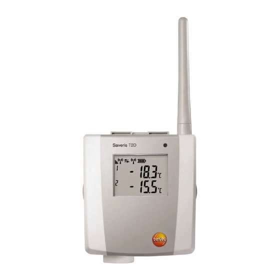
4 Product description Pos: 34 /TD/Produktbeschreibung/Übersicht/testo Saveris/01 Funkfühler/02 Funkfühler mit Display @ 0\mod_1189496687343_79.doc @ 4264 4.3.2. Radio probe with display Display for showing reading, battery and connection status as well as the field strength of the radio link. LED for status display. - Page 23 ( ) limit value or undershot the lower ( ) limit value. Number of the channel. Display for a second sensor in the probe. Pos: 35 /TD/Produktbeschreibung/Übersicht/testo Saveris/01 Funkfühler/03 Bedeutung der LED @ 0\mod_1190807440000_79.doc @ 5133 0970 4020 en 01 testo AG...
-
Page 24: Meaning Of The Led Displays At The Probes
The connection to the Saveris base failed. Status displays during operation Briefly press the connect button on the rear of the probe once and the LED shows the status of the connection to the Saveris base. Representation Explanation A very good connection to the Saveris Flashing 3 x green base exists. -
Page 25: Saveris Ethernet Probes
4 Product description Pos: 36 /TD/Produktbeschreibung/Übersicht/testo Saveris/02 Ethernet-Fühler/00 Ethernet-Fühler @ 1\mod_1197555728828_79.doc @ 6366 4.4. Saveris Ethernet probes Pos: 37 /TD/Produktbeschreibung/Übersicht/testo Saveris/02 Ethernet-Fühler/02 Ethernet-Fühler @ 1\mod_1197555730062_79.doc @ 6386 Display for showing the reading and transmission information. LED for status display. Connect button. - Page 26 4 Product description Displays Quality of the connection. Battery status. Indicator as to whether a communication with the Saveris base is performed. Unit of the reading: • for humidity measurement • for current measurement • °Ctd °Ftd for dewpoint measurement.
-
Page 27: Saveris Router
4 Product description Pos: 38 /TD/Produktbeschreibung/Übersicht/testo Saveris/03 Router/01 Router @ 1\mod_1197555862937_79.doc @ 6406 4.5. Saveris router Antenna for the radio transmission of the measurement data LED for status display Connect button for connecting the router to the Saveris base and for a status request during operation... -
Page 28: Saveris Converter
4 Product description Pos: 39 /TD/Produktbeschreibung/Übersicht/testo Saveris/04 Converter/01 Converter @ 1\mod_1197557086312_79.doc @ 6416 4.6. Saveris converter Antenna for receiving the measurement data. LED for status display. Connect button for connecting the converter to the Saveris base and for a status request during operation. -
Page 29: First Steps
• 3 Saveris T1 NTC radio probes without display with wall bracket and batteries Pos: 44 /TD/Erste Schritte/testo Saveris/01 Lieferumfang/01 Set 1 SBE @ 1\mod_1197989725515_79.doc @ 6673 • USB cable for the connection of the Saveris base to the computer. -
Page 30: Set 3
• 5 Saveris T1D NTC radio probes with display and with wall bracket and batteries Pos: 46 /TD/Erste Schritte/testo Saveris/01 Lieferumfang/02 Set 2 SBE @ 1\mod_1197989908312_79.doc @ 6713 • USB cable for the connection of the Saveris base to the computer. -
Page 31: Flowchart
5 First steps Pos: 50 /TD/Erste Schritte/testo Saveris/00 Ablaufdiagramm Inbetriebnahme @ 0\mod_1189581707421_79.doc @ 4454 5.2. Flowchart Start Base with Inserting SIM card GSM module? (page Connecting USB cable and power supply to base Connecting (page 31 / page USB cable and... - Page 32 5 First steps Installing software (page Integrating Ethernet Use Ethernet probe probes? (page Integrating converter converter? (page Connecting Saveris base to PC and starting up hardware (page Starting software (page Creating zones (page 86 Performing the test run (page Configuring the...
-
Page 33: Inserting Sim Card (Optional)
5 First steps Pos: 51 /TD/Erste Schritte/testo Saveris/00 SIM-Karte einsetzen @ 1\mod_1197557316734_79.doc @ 6426 5.3. Inserting SIM card (optional) With a Saveris base with integrated GSM module, you must insert the SIM card. The SIM card for sending SMS messages is not included in the delivery and must be purchased separately from a mobile phone provider. -
Page 34: Connecting Usb Cable To The Saveris Base
5 First steps Pos: 52 /TD/Erste Schritte/testo Saveris/01 USB-Kabel an Base anschließen @ 0\mod_1190210196906_79.doc @ 4930 5.4. Connecting USB cable to the Saveris base 1. Loosen and remove screw connection. 2. Remove cover from Saveris Base. 3. Plug the USB cable into the Saveris base. -
Page 35: Connecting Gsm Antenna (Optional)
Pos: 55 /TD/Erste Schritte/testo Saveris/01c Antenne anschließen @ 1\mod_1202123742093_79.doc @ 8056 > Place antenna cable on the coaxial connection screw on Pos: 56 /TD/Erste Schritte/testo Saveris/02 Base mit Stromversorgung verbinden @ 0\mod_1188477940515_79.doc @ 2955 0970 4020 en 01 testo AG... -
Page 36: Connecting Saveris Base With Power Supply
Pos: 57 /TD/Erste Schritte/testo Saveris/02a-1 Stromversorgung über Netzteil verbinden @ 0\mod_1191328326843_79.doc @ 5392 5.6.1. Power supply via mains unit Pos: 58 /TD/Erste Schritte/testo Saveris/02a-2 SBE Stromversorgung über Netzteil verbinden @ 1\mod_1200057993442_79.doc @ 7524 Pos: 59 /TD/Erste Schritte/testo Saveris/02a-3 Stromversorgung über Netzteil verbinden @ 1\mod_1200058046031_79.doc @ 7546 1. Connect mains cable to the Saveris base. -
Page 37: Power Supply Via Plug-In/Screw Connection (Optional)
5.6.2. Power supply via plug-in/screw connection (optional) Pos: 61 /TD/Erste Schritte/testo Saveris/02b-2 SBE Stromversorgung über AC/DC verbinden @ 1\mod_1202124389613_79.doc @ 8067 Pos: 62 /TD/Erste Schritte/testo Saveris/02b-3 Stromversorgung über AC/DC verbinden @ 1\mod_1202124473316_79.doc @ 8089 1. Loosen clamping screws no. 1 and no. 2. -
Page 38: Inserting Batteries In The Probes
5 First steps Pos: 63 /TD/Erste Schritte/testo Saveris/02 b Batterien am Fühler einlegen @ 0\mod_1191322124515_79.doc @ 5263 5.7. Inserting batteries in the probes 1. Loosen screws on the rear of the probe. 2. Remove housing cover of probe 3. Insert batteries Ensure that you insert the batteries correctly. -
Page 39: Connecting Radio Probe
5 First steps Pos: 64 /TD/Erste Schritte/testo Saveris/03 Fühler an der Base anmelden @ 0\mod_1188478029328_79.doc @ 2964 Integrating Saveris router (optional) Page 52 5.8. Connecting radio probe You can connect a maximum of 15 probes to the Saveris base directly via radio. - Page 40 Multiple probes cannot be connected at the Saveris base simultaneously. Multiple probes can only be connected one after the other.
-
Page 41: Installing Saveris Software
• red, no radio link exists. If no radio link to the Saveris base exists even after a change of location of the probe, connect a router to the Saveris base; see Integrating Saveris router (optional), page Pos: 65 /TD/Erste Schritte/testo Saveris/05a Saveris-Software installieren @ 0\mod_1188478151968_79.doc @ 2991... -
Page 42: Starting Up Hardware
5 First steps Pos: 66 /TD/Erste Schritte/testo Saveris/04 Hardware inbetriebnehmen @ 0\mod_1188478113640_79.doc @ 2982 5.10. Starting up hardware The following preconditions must be fulfilled for the startup of the hardware: • the Saveris base is ready for operation, • all probes are connected to the Saveris base and •... - Page 43 Saveris base. 4. Click on [Continue >] If the Saveris base is equipped with a GSM module the dialogue for entering the basic settings for the SMS service is shown. If there is no GSM module continue with step 7.
- Page 44 You can find the PIN and the number of the SMS centre in the documents for your SIM card. The list of the probes registered in the Saveris base is shown. The fields of the...
- Page 45 > Perform step 5 and the following for all other probes until all required fields are filled. 7. Click on [Continue >] The settings for measuring cycle, the alarm delay and the alarm issue are shown. 0970 4020 en 01 testo AG...
- Page 46 Determine Alarm delay If you enter the value "5" for example, an alarm is not triggered by the Saveris base until the fifth time that the limit value is exceeded. Later the settings can be changed for every probe separately in the software.
- Page 47 5 First steps 11. Click on [Continue > If a router is connected at the Saveris base the configuration of the connection type for the probes is shown. If no router is connected continue with step 15. 12. Click in the...
- Page 48 5 First steps 16. Enter the Telephone number of the recipient of the alarm messages. Enter with country code, network or area code and local number. 17. Activate Forward checkbox if the alarm message should be sent to a second recipient if recipient 1 does not respond. list field and the 2nd telephone number input field...
- Page 49 Outlook contacts using the [Address book] > Enter text for the subject line of the e-mail. 25. Enter the address under Cover sheet address field that should be displayed on the top of the report. 0970 4020 en 01 testo AG...
- Page 50 5 First steps 26. Click on [Continue > The wizard is shown with the information on the start of measurement and the list of the registered probes. 27. Postpone the start of measurement, if necessary. > Change the project name in the Name field.
- Page 51 30. Consecutively press the connect button on all probes to synchronize the probes. 31. Close the dialogue with [OK] The hardware is now ready for operation. Pos: 67 /TD/Produkt verwenden/testo Saveris/01 Start/01_Saveris-Software starten @ 0\mod_1189076832593_79.doc @ 3933 0970 4020 en 01 testo AG...
-
Page 52: Starting Saveris Software
3. Select the project that is to be opened in the tree structure. 4. Confirm with [OK] Testo Saveris software program window is shown with the selected data record in the foreground. Pos: 68 /TD/Erste Schritte/testo Saveris/Hardware erweitern/Messsystem erweitern @ 1\mod_1197551581796_79.doc @ 6327 0970 4020 en 01... -
Page 53: Expand Measuring System
Expand measuring system In this chapter, you learn how to integrate the Saveris router, converter and Ethernet probes into the measuring system. Pos: 69 /TD/Erste Schritte/testo Saveris/Hardware erweitern/01 Router einbinden/00 Router einsetzen @ 1\mod_1197549116203_79.doc @ 6304 5.12.1. Integrating Saveris router (optional) -
Page 54: Connecting Router With Power Supply (Mains Unit)
5 First steps Pos: 70 /TD/Erste Schritte/testo Saveris/Hardware erweitern/01 Router einbinden/01 Router-Strom @ 1\mod_1197548324640_79.doc @ 6294 5.12.1.1. Connecting router with power supply (mains unit) 1. Open cover 2. Insert mains cable 3. Insert mains plug into a socket. The wall mounting of a router is performed in the same ways as for a probe;... -
Page 55: Connecting Router With Power Supply (Ac/Dc)
5 First steps Pos: 71 /TD/Erste Schritte/testo Saveris/Hardware erweitern/01 Router einbinden/01b Router-ACDC @ 1\mod_1197978273593_79.doc @ 6543 5.12.1.2. Connecting router with power supply (AC/DC) 1 Remove protection caps 2. Loosen screws on the rear of the router. 3. Remove housing cover of router 4. - Page 56 5 First steps 5. Loosen clamping screws 6. Route cabling through the cable opening and insert in the terminals It is not necessary to note the polarity. 7. Tighten clamping screws. 0970 4020 en 01...
- Page 57 The wall mounting of a router is performed in the same ways as for a probe; see "Mounting the probe on the wall". Pos: 72 /TD/Erste Schritte/testo Saveris/Hardware erweitern/01 Router einbinden/02 Router anmelden @ 1\mod_1197548238578_79.doc @ 6274 0970 4020 en 01 testo AG...
-
Page 58: Connecting Router
1. Change to the Info System menu at the Saveris base with [▼] button. 2. Press [Enter] to call up the Login function. The status bar in the display shows that the Saveris base is ready for router detection. 0970 4020 en 01... -
Page 59: Assigning Probes
Press [Enter] if further components are to be connected; see previous step. Pos: 73 /TD/Erste Schritte/testo Saveris/Hardware erweitern/01 Router einbinden/03 Fühler zuweisen @ 1\mod_1197548250906_79.doc @ 6284 5.12.1.4. Assigning probes To assign a probe to a router, both must be connected in the Saveris base. - Page 60 2. Click on [Continue >] System status dialogue with the General tab is shown. 3. Change to Router tab. Direct connection type means that the probe is connected directly in the Saveris base or a converter. 0970 4020 en 01...
- Page 61 > Perform steps 4 to 6 for all remaining probes whose measurement data is to be transmitted to the Saveris base via a router. 7. Position the probes and router at their mounting locations to check the radio links.
-
Page 62: Integrating Saveris Ethernet Probe (Optional)
If no radio link exists after changing the location of the probe and/or router, introduce a converter; see "Integrating Saveris converter (optional)". Pos: 74 /TD/Erste Schritte/testo Saveris/Hardware erweitern/03 Ethernet-Fühler einbinden/00 Ethernet-Fühler einsetzen @ 1\mod_1197552336953_79.doc @ 6336 5.12.2. Integrating Saveris Ethernet probe (optional) In addition to the Saveris radio probes, you can use probes that are connected to the Ethernet interface of the Saveris base. -
Page 63: Connecting The Network Cable
Use a network cable with a diameter between 5.8 mm and 6.8 mm to ensure the leaktightness of the probe housing. 1. Loosen screws on the rear of the probe and remove the housing cover 0970 4020 en 01 testo AG... - Page 64 Ethernet jack until it engages. If you wish to connect the Saveris Ethernet probe to the power supply via the 24 V AC/DC plug-in/screw terminal and not via the mains adapter, do not screw on the housing cover until after connecting the power supply.
-
Page 65: Connecting Ethernet Probe With Power Supply (Mains Unit).64
You can connect the probe to the network via a network hub or directly at the Saveris base via the Ethernet jack. Pos: 76 /TD/Erste Schritte/testo Saveris/Hardware erweitern/03 Ethernet-Fühler einbinden/01c Stromversorgung @ 1\mod_1203423817781_79.doc @ 8270 5.12.2.2. Connecting Ethernet probe with power supply (mains unit) -
Page 66: Connecting Usb Cable And Installing Driver
4. Connect the USB cable to the computer. The wizard for the installation of the driver is started. 5. Follow the directions of the installation wizard. Pos: 78 /TD/Erste Schritte/testo Saveris/Hardware erweitern/03 Ethernet-Fühler einbinden/02 Software installieren @ 1\mod_1203421488750_79.doc @ 8215 0970 4020 en 01... -
Page 67: Installing Parameterization Software
4. Follow the directions of the installation wizard. The software is ready to be used after restarting the computer. Pos: 79 /TD/Erste Schritte/testo Saveris/Hardware erweitern/03 Ethernet-Fühler einbinden/03 Verbindungsdaten zuweisen @ 1\mod_1203421515781_79.doc @ 8226 5.12.2.5. Assigning connection data You must now enter the connection settings for the Ethernet probes. - Page 68 Netmask Gateway The first two blocks of the IP address must match those from the Saveris base. The last two blocks can be selected freely. However, the IP address may not yet be assigned. The IP address, the netmask and the gateway can be...
- Page 69 5 First steps 5. Enter IP address of the Saveris base. The IP address can be read off at the Saveris base in Info Base menu; also see chapter Displays, page 6. Click on [Finish] The Ethernet probe is restarted, synchronized with the Saveris base and the number of connected Ethernet probes in the display of the base is increased by 1;...
- Page 70 5 First steps Displays, page 16. Pos: 80 /TD/Erste Schritte/testo Saveris/Hardware erweitern/03 Ethernet-Fühler einbinden/04 Netzwerkkabel an Base anschließen @ 1\mod_1203430798656_79.doc @ 8313 0970 4020 en 01...
-
Page 71: Connecting The Network Cable To The Saveris Base
1. Loosen and remove screw connection. 2. Remove cover from Saveris Base. 3. Plug the network cable into the Saveris base. Pos: 81 /TD/Erste Schritte/testo Saveris/Hardware erweitern/03 Ethernet-Fühler einbinden/05 Ethernet-Fühler inbetrieb nehmen @ 1\mod_1203421551984_79.doc @ 8237 0970 4020 en 01 testo AG... - Page 72 5 First steps 5.12.2.7. Starting up Ethernet probes 1. Open the assistant for starting up new hardware component Start All Programs Testo Startup Assistant The assistant is opened with the welcome screen. 2. Click on [Continue >] Commission new probe dialogue is shown.
- Page 73 5 First steps 3. Leave default setting and click on [Continue >]. The list of the probes newly registered in the Saveris base is shown. 0970 4020 en 01 testo AG...
- Page 74 The limit values determine as of which reading the Saveris base triggers an alarm. 4. Click in the Channel name field and enter the designation of the probe, e.g.
- Page 75 (minute) • (hour). 7. Determine Alarm delay If you enter the value "5" for example, an alarm is not triggered by the Saveris base until the fifth time that the limit value is exceeded. 0970 4020 en 01 testo AG...
- Page 76 Relay of the Saveris base. The notification function via is only available if the Saveris base is equipped with a GSM module. Click on [Continue >] The wizard is shown with the setting for the start of measurement and the list of the newly registered probes.
-
Page 77: Integrating Saveris Converter (Optional)
5 First steps Pos: 82 /TD/Erste Schritte/testo Saveris/Hardware erweitern/02 Converter einbinden/00 Converter einsetzen @ 1\mod_1197550607093_79.doc @ 6315 5.12.3. Integrating Saveris converter (optional) If the distance between the radio probe or router is too large for a radio transmission, you can integrate a Saveris converter into the measuring system. -
Page 78: Performing The Test Run
Performing the test run The test run must be performed to ensure proper operation of the measuring system. Pos: 84 /TD/Erste Schritte/testo Saveris/06 ****Probelauf/01 Systemverfügbarkeit prüfen @ 0\mod_1189157395875_79.doc @ 4094 5.13.1. Checking system availability Wait for the first connection between the Saveris base and the probes to check the system availability. -
Page 79: Checking Alarm Chain
2. Click on the [Test report] button. A test report is sent to the mobile phone number entered. Pos: 86 /TD/Erste Schritte/testo Saveris/07 **** Montage der Hardware/00 Hardware montieren @ 0\mod_1189157579984_79.doc @ 4124 0970 4020 en 01 testo AG... -
Page 80: Mounting The Hardware
After mounting, perform another test run of the system; also see "Performing the test run". Pos: 87 /TD/Erste Schritte/testo Saveris/07 **** Montage der Hardware/01 Base an der Wand montieren @ 0\mod_1189157492531_79.doc @ 4105 5.14.1. Mounting the Saveris base on the wall... - Page 81 5 First steps 5. Place Saveris base on the wall bracket and secure with screw Pos: 88 /TD/Erste Schritte/testo Saveris/07 **** Montage der Hardware/01b Base mit Standfuß @ 0\mod_1190975629546_79.doc @ 5233 0970 4020 en 01 testo AG...
-
Page 82: Setting Up Saveris Base With Stand
The Saveris base must be positioned close enough to the computer used and a possible power supply in accordance with the cabling provided. 1. Place the Saveris base on the stand 2. Set up the Saveris base at the desired location. 0970 4020 en 01... -
Page 83: Mounting The Probe On The Wall
5 First steps Pos: 89 /TD/Erste Schritte/testo Saveris/07 **** Montage der Hardware/03 Fühler montieren @ 0\mod_1189157541812_79.doc @ 4114 5.14.3. Mounting the probe on the wall When selecting the location, take into account the following points: • The range of the probe may not be exceeded; see "Connecting radio probe"... -
Page 84: Checking The Measuring System Again
Please refer to "Removing probe from wall bracket" for removing the probe from the wall bracket. Pos: 90 /TD/Erste Schritte/testo Saveris/07 **** Montage der Hardware/04 System prüfen @ 0\mod_1191327191562_79.doc @ 5362 5.14.4. Checking the measuring system again >... -
Page 85: Using The Product
Pos: 93 /TD/Produkt verwenden/testo Saveris/01 Start/02_Bedienoberfläche_01 @ 0\mod_1189076833359_79.doc @ 3943 6.1. User interface In this chapter, you learn how the user interface of the Saveris software is designed. Pos: 94 /TD/Produkt verwenden/testo Saveris/01 Start/02_Bedienoberfläche_02_SBE @ 1\mod_1197983794406_79.doc @ 6583 Pos: 95 /TD/Produkt verwenden/testo Saveris/01 Start/02_Bedienoberfläche_03 @ 1\mod_1197983802515_79.doc @ 6603... - Page 86 Templates Selection of the report heads and editing functions for the templates. Pos: 96 /TD/Produkt verwenden/testo Saveris/01 Start/02_Bedienoberfläche_04 @ 1\mod_1197983805828_79.doc @ 6613 Data range The measurement data are managed in the data range. You can create new groups of readings and copy the data from individual channels within the groups.
-
Page 87: Menus And Commands
Pos: 100 /TD/Produkt verwenden/testo Saveris/01 Start/02_Bedienoberfläche_08 @ 1\mod_1197984029171_79.doc @ 6663 Status bar Shows the status information for the software. Pos: 101 /TD/Produkt verwenden/testo Saveris/02 Menüs und Befehle der Ribbon-Leiste/00 Menüs und Befehle @ 0\mod_1190279903078_79.doc @ 4975 6.2. Menus and commands In this chapter, you learn which menus and commands are available to you and what you can use these commands for. - Page 88 Copy Copies the marked element onto the clipboard. Paste Pastes the contents of the clipboard at the current position. Pos: 105 /TD/Produkt verwenden/testo Saveris/02 Menüs und Befehle der Ribbon-Leiste/01 Start/02 Bearbeiten @ 0\mod_1189605697875_79.doc @ 4494 0970 4020 en 01...
- Page 89 Changes to the presentation of the data in a table. Alarms Opens or closes the alarm overview and acknowledgement. Pos: 108 /TD/Produkt verwenden/testo Saveris/02 Menüs und Befehle der Ribbon-Leiste/02 Bearbeiten/00 Menü Bearbeiten @ 0\mod_1190280106796_79.doc @ 4993 0970 4020 en 01 testo AG...
-
Page 90: Edit
6 Using the product 6.2.2. Edit Pos: 109 /TD/Produkt verwenden/testo Saveris/02 Menüs und Befehle der Ribbon-Leiste/02 Bearbeiten/02 Bearbeiten (Diagramm) @ 0\mod_1189606502281_79.doc @ 4555 Edit in the diagram view Edit (diagram) menu is only shown if the diagram is activated by clicking in the window. - Page 91 (diagram) menu Menu Description function Upper limit Maximum of the shown range of values. range of values Lower limit Minimum of the shown range of values. range of values Grid Scaling of the value axis. 0970 4020 en 01 testo AG...
- Page 92 Grid Scaling of the time axis. Pos: 110 /TD/Produkt verwenden/testo Saveris/02 Menüs und Befehle der Ribbon-Leiste/02 Bearbeiten/03 Bearbeiten (Tabelle) @ 0\mod_1189606537468_79.doc @ 4565 Edit in the table view Edit (table) menu is only shown if the table is activated by clicking in the window.
-
Page 93: Options
6 Using the product 6.2.3. Options Pos: 112 /TD/Produkt verwenden/testo Saveris/02 Menüs und Befehle der Ribbon-Leiste/03 Extras/01 Verwaltung @ 1\mod_1197373808453_79.doc @ 6173 Extras Management menu Menu Description function Projects Opens the dialogue for selecting a project. Protocols Opens a protocol file that you can send to Customer Service in the event of a problem. -
Page 94: Template
A link is thus formed between the file and the service data and WordPad. Pos: 117 /TD/Produkt verwenden/testo Saveris/02 Menüs und Befehle der Ribbon-Leiste/05 Menü Vorlage @ 0\mod_1190280258593_79.doc @ 5013 6.2.4. Template Pos: 118 /TD/Produkt verwenden/testo Saveris/02 Menüs und Befehle der Ribbon-Leiste/05 Vorlage @ 0\mod_1188997033281_79.doc @ 3727... -
Page 95: Creating And Deleting Zones
You could perhaps combine probes that are located in store rooms into one zone and probes that are in cold rooms into another. Pos: 122 /TD/Produkt verwenden/testo Saveris/03 Gruppen einrichten/organisieren/04 Zonen anlegen @ 0\mod_1189076726062_79.doc @ 3902 6.3.1. Creating zones 1. -
Page 96: Configuring The Alarms
6 Using the product Pos: 124 /TD/Produkt verwenden/testo Saveris/04 Alarme konfigurieren/00 Alarme konfigurieren @ 0\mod_1189063396359_79.doc @ 3852 6.4. Configuring the alarms The testo Saveris measurement system differentiates between two types of alarm, which can be configured independent of one another: •... - Page 97 The notification function via is only available if the Saveris base is equipped with a GSM module. 3. Perform the required settings. When exiting the basic settings the settings are saved. 0970 4020 en 01 testo AG...
-
Page 98: Configuring The Probe Alarm
The channel-specific settings for the alarms are shown in the display range. Pos: 127 /TD/Produkt verwenden/testo Saveris/04 Alarme konfigurieren/02 Spezifischer Alarm - 01 Grenzwerte @ 0\mod_1189064521015_79.doc @ 3871 Limit values Designation... -
Page 99: Alarm Overview
Explanation Delay (min) With a delay of how many measuring cycles should the alarm be triggered? Pos: 129 /TD/Produkt verwenden/testo Saveris/04 Alarme konfigurieren/02 Spezifischer Alarm - 03 Ausgabe @ 0\mod_1189064615828_79.doc @ 3891 Output targets Designation Explanation Determining in which form the probe E-mail alarms should be issued. - Page 100 Alarm relay base basic settings. Active Specification as to whether the alarm for the probe is activated under System Radio probe Pos: 131 /TD/Produkt verwenden/testo Saveris/05 Messreihen analysieren @ 0\mod_1190895859625_79.doc @ 5163 0970 4020 en 01...
-
Page 101: Analyzing Series Of Measurements
• Table function if the data should be displayed as a table. Pos: 132 /TD/Produkt verwenden/testo Saveris/05a Diagramme analysieren/00 Diagramme @ 0\mod_1188996581406_79.doc @ 3484 6.5.1. Diagram view In this view, the readings are shown as line diagrams. In the... -
Page 102: Information On A Reading (Crosshairs)
In doing this, it is not necessary to exactly follow the course of the curve; the crosshairs does this automatically if you move the mouse to the right or left. Pos: 135 /TD/Produkt verwenden/testo Saveris/05a Diagramme analysieren/03 Bereich markieren @ 0\mod_1188996582687_79.doc @ 3514 6.5.1.3. Marking the area Mark an area of the diagram to show the statistical computation for a portion of the curve, for example. -
Page 103: Showing Regression Curve
If you click on the curve again, the regression curve is hidden again. Pos: 137 /TD/Produkt verwenden/testo Saveris/05a Diagramme analysieren/05 Text einfügen @ 0\mod_1188996583250_79.doc @ 3534 6.5.1.5. Inserting text Insert text in the diagram, for example to mark distinctive measurement points. -
Page 104: Erasing Text
Edit Tools Erase text The text field is deleted. Pos: 139 /TD/Produkt verwenden/testo Saveris/05a-2 Kurveneigenschaften/00 Kurveneigenschaften @ 0\mod_1188996704171_79.doc @ 3636 6.5.1.7. Characteristics of a curve You can adapt the representation of a measurement series to your requirements. For example, you can change the line weight of a curve or the representation of the limit values in the diagram. - Page 105 6 Using the product Pos: 140 /TD/Produkt verwenden/testo Saveris/05a-2 Kurveneigenschaften/01 Register Kurve bearbeiten @ 0\mod_1188996705609_79.doc @ 3666 Curve Designation Explanation Smooth The measurement points are connected by an interpolated curve; the plot-points on the curve between two measurement points are estimated mathematically.
- Page 106 6 Using the product Pos: 141 /TD/Produkt verwenden/testo Saveris/05a-2 Kurveneigenschaften/02 Register Grenzwertanzeige @ 0\mod_1188996705265_79.doc @ 3656 Range limits Designation Explanation Display area limit Specification as to whether the limit values should be shown in the diagram. Add limit labels Specification as to whether the limit...
- Page 107 6 Using the product Pos: 142 /TD/Produkt verwenden/testo Saveris/05a-2 Kurveneigenschaften/03 Register Datenreihe @ 0\mod_1188996704453_79.doc @ 3646 Data sequence Designation Explanation Upper limit values Specification of the upper limit value. Lower limit values Specification of the lower limit value. Name Designation of curve.
- Page 108 , if an area was marked. Specification that the given values are only valid for the selected area of the measurement curve. Pos: 144 /TD/Produkt verwenden/testo Saveris/05a-3 Achseinstellungen/05 Einstellungen für die Achsen im Diagramm @ 0\mod_1193999542168_79.doc @ 5684 0970 4020 en 01...
-
Page 109: Settings For The Axes In The Diagram
Change the settings of the axes in the diagram to adapt the representation to your requirements. Pos: 145 /TD/Produkt verwenden/testo Saveris/05a-3 Achseinstellungen/06 Werteachse @ 0\mod_1193999542824_79.doc @ 5694 Settings for the value axis > With the right mouse button, click on the desired value axis in the diagram. - Page 110 (if manual Manual entry of the grid. division is activated) Pos: 146 /TD/Produkt verwenden/testo Saveris/05a-3 Achseinstellungen/07 Zeitachse @ 0\mod_1193999544199_79.doc @ 5704 Settings for the time axis > With the right mouse button, click on the time axis in the diagram.
- Page 111 Interval (if manual Manual entry of the grid. division is activated) Selection list for Unit of the time axis: the unit (if manual • (second) division is activated) • (minute) • (hour) • (day). 0970 4020 en 01 testo AG...
-
Page 112: Marking Readings
The table view of the selected data is shown. > If necessary, deactivate channels via the checkboxes for the display. Pos: 148 /TD/Produkt verwenden/testo Saveris/05b Tabellen analysieren/01 Messwerte markieren @ 0\mod_1188996635625_79.doc @ 3565 6.5.2.1. Marking readings Mark specific readings to perform a statistical computation for part of the measurement series, for example. -
Page 113: Dropping The Marking
Tools Drop marking The marking of the readings is deleted. Pos: 150 /TD/Produkt verwenden/testo Saveris/05b Tabellen analysieren/03 Extremwert oder Mittelwert einfügen @ 0\mod_1188996637890_79.doc @ 3585 6.5.2.3. Inserting extreme values or mean in the table Insert the minimum/maximum reading as well as the mean from the whole table at the end of the table. -
Page 114: Compressing Readings
Possible settings for the unit: • (second) • (minute) • (hour) • (day). 3. Click on [OK] The dialogue is closed and the table is shown compressed. Pos: 152 /TD/Produkt verwenden/testo Saveris/05b Tabellen analysieren/05 Verdichtung aufheben @ 0\mod_1188996639140_79.doc @ 3605 0970 4020 en 01... -
Page 115: Dropping Compression
Dropping compression > Click on Edit Tools Drop compression The table is shown again in its uncompressed form. Pos: 153 /TD/Produkt verwenden/testo Saveris/05b Tabellen analysieren/07 größter Messwert @ 0\mod_1188996639859_79.doc @ 3625 6.5.2.6. Determining largest reading > In the Edit Find... -
Page 116: Acknowledge The Alarm
> If needed, enter Comments on an alarm in the column of the same name. Pos: 157 /TD/Produkt verwenden/testo Saveris/06c Alarme analysieren/02 Alarm quittieren @ 0\mod_1189079436328_79.doc @ 3973 6.6.2. Acknowledge the alarm If you acknowledge an alarm at the Saveris base, this is carried over into the software. - Page 117 Designation of the individual channels of the registered probes. The channel delivers measurement data within the limit values. A limit value has been breached and the Saveris base has triggered an alarm. Time Date and time, when the alarm was triggered.
-
Page 118: Creating Evaluations
As soon as the confirmation is received in the Saveris base, the alarm relay stops flashing and the alarm is deleted. Pos: 158 /TD/Produkt verwenden/testo Saveris/07 Berichte/00 Berichte erstellen @ 0\mod_1190280535671_79.doc @ 5032 6.7. Creating evaluations You can print out series of measurements or have reports on the data automatically created by the software in definable intervals. -
Page 119: Archiving With Automatic Reports
• input options for "Conditions" and • other comment lines. Pos: 160 /TD/Produkt verwenden/testo Saveris/07 Berichte/02 ** Automatische Berichte @ 0\mod_1189522147015_79.doc @ 4304 6.7.2. Archiving with automatic reports A simple and secure option for archiving your data is the automatic creation of reports. - Page 120 6 Using the product Pos: 161 /TD/Produkt verwenden/testo Saveris/07 Berichte/03 ** Langzeitarchivierung und Datensicherung @ 0\mod_1190970854000_79.doc @ 5223 6.8. Creating a new database (project) The licence-free database system Microsoft SQL Server 2005 Express is installed as standard with the testo Saveris software.
- Page 121 To be able to start a new project, you must reconnect all components to the Saveris base and then start up the hardware again. Pos: 162 /TD/Produkt verwenden/testo Saveris/09 Einstellungen System/00 Einstellungen System @ 0\mod_1189493729343_79.doc @ 4233 0970 4020 en 01 testo AG...
-
Page 122: System Settings
Converter with the settings for the converters connected to the Saveris base. Pos: 163 /TD/Produkt verwenden/testo Saveris/09 Einstellungen System/01 Allgemein @ 0\mod_1188997905046_79.doc @ 3801 6.9.1. General settings for the Saveris base Using this menu item you can, for example, synchronize the date and time of the Saveris base with the values from the computer or change the IP address of the Saveris base. -
Page 123: System Settings For The Gsm Module
Saveris base. IP address IP address of the Saveris base. Pos: 164 /TD/Produkt verwenden/testo Saveris/09 Einstellungen System/02 SMS-Modul @ 0\mod_1188997905750_79.doc @ 3811 6.9.2. System settings for the GSM module Using this menu item, you enter the data of the SIM card and can determine whether the alarm messages are to be sent again if the first attempt at sending them should fail. -
Page 124: Show Operating Data Of The Probes
PIN number of SIM card. SMS centre Number of the message centre. Pos: 165 /TD/Produkt verwenden/testo Saveris/09 Einstellungen System/03 Betriebsdaten @ 1\mod_1197536994375_79.doc @ 6253 6.9.3. Show operating data of the probes. Using this menu item, you can check when the last data were received from a probe, for example, and the duration until the next readings can be expected. -
Page 125: Settings For The Radio Probe
Duration in minutes until the probe [min] delivers the next data. Pos: 166 /TD/Produkt verwenden/testo Saveris/09 Einstellungen System/03 Wireless probes @ 0\mod_1189598701171_79.doc @ 4463 6.9.4. Settings for the radio probe Using this menu item you can, for example, check the battery status of the probe or the quality of the radio transmission. -
Page 126: Ethernet Probes
AlMn Energizer Type Specification of the probe type. Pos: 167 /TD/Produkt verwenden/testo Saveris/09 Einstellungen System/04 Ethernet probes @ 0\mod_1190896768531_79.doc @ 5172 6.9.5. Ethernet probes Using this menu item, you can, for example, check the version of the instrument software or the IP address of an Ethernet probe. - Page 127 Interval in which the measurements should be performed. Type Specification of the probe type. Pos: 168 /TD/Produkt verwenden/testo Saveris/09 Einstellungen System/05 Router @ 1\mod_1197537685343_79.doc @ 6263 6.9.6. Router Using this menu item, assign which radio probes should transfer their measurement data to the Saveris base via a router.
-
Page 128: Report Settings
2. Click in the connection type cell of the probe which is to be assigned to a router. The cell is shown as a selection list. Pos: 169 /TD/Produkt verwenden/testo Saveris/10 Einstellungen Berichte/00 Einstellungen Berichte @ 0\mod_1189494078218_79.doc @ 4243 6.10. Report settings In the report settings, you can determine how the automatic reporting should take place. - Page 129 2. Click on Settings for reports The report settings are shown in the display range. Pos: 170 /TD/Produkt verwenden/testo Saveris/10 Einstellungen Berichte/01 Settings @ 0\mod_1188997925140_79.doc @ 3821 Designation Explanation [New report] Adds a new reporting task to the list.
- Page 130 The storage location for the reports was determined during the installation of the Saveris software. Generally this is C:\Documents and Settings\All Users\Documents\Saveris Small Business Edition. Pos: 171 /TD/--- Seitenwechsel --- @ 0\mod_1173774430601_0.doc @ 283...
-
Page 131: Maintaining The Product
7 Maintaining the product Pos: 172 /TD/Überschriften/7. Produkt instand halten @ 0\mod_1173789831362_79.doc @ 397 Maintaining the product Pos: 173 /TD/Produkt instand halten/testo Saveris/00 Ersatz von Komponenten @ 0\mod_1188476464890_79.doc @ 2909 7.1. Replacement of components You can shut down a component – probe, converter or router –... - Page 132 7 Maintaining the product 3. Change to Projects tab. 4. Click on [Log out component] Log out component dialogue is shown. 5. Activate the checkbox in front of the component that is to be logged out of the system. 6. Click on [OK] A query to erase the components from the configuration is shown.
-
Page 133: Adding Components
7 Maintaining the product Pos: 175 /TD/Produkt instand halten/testo Saveris/02 Komponenten hinzufügen @ 0\mod_1188476503984_79.doc @ 2918 7.1.2. Adding components 1. Connecting new probes at the Saveris base; see "Connecting radio probe". 2. Start up testo Saveris software. The software recognizes that a new probe is located in the system and the wizard for the installation of a new component is started. - Page 134 7 Maintaining the product 4. Leave default setting and click on [Continue >] The list of the probes newly registered in the Saveris base is shown. 0970 4020 en 01...
- Page 135 The limit values determine as of which reading the Saveris base triggers an alarm. 5. Click in the Channel name field and enter the designation of the probe, e.g.
- Page 136 8. Determine Alarm delay If you enter the value "5" for example, an alarm is not triggered by the Saveris base until the fifth time that the limit value is exceeded. 9. Determine in which cases a system alarm should be triggered.
- Page 137 13. Perform steps 11 and 12 for all remaining probes whose measurement data is to be transmitted to the Saveris base via a router. 14. Click on [Continue >] The wizard is shown with the setting for the start of measurement and the list of the newly registered probes.
-
Page 138: Calibration And Adjustment
[OK] to confirm the note. The new hardware is now ready for operation. Pos: 176 /TD/Produkt instand halten/testo Saveris/Kalibrierung und Justage @ 0\mod_1188476360640_79.doc @ 2882 7.2. Calibration and adjustment All testo Saveris probes are adjusted in the factory, which is confirmed by the corresponding adjustment report. -
Page 139: Removing Probe From Wall Bracket
7 Maintaining the product Pos: 177 /TD/Produkt instand halten/testo Saveris/Fühler von Wandhalterung abnehmen @ 0\mod_1191328027078_79.doc @ 5382 7.3. Removing probe from wall bracket 1. Using a narrow flat tip screwdriver release the probe from the wall bracket 2. Remove probe from wall bracket towards top, as shown. -
Page 140: Changing Batteries At Probe
• 3 years with Energyzer L91 Photo lithium batteries for freezer applications. You can check the battery status of the probes via the Saveris software. To do so, select the probe that you wish to check under System Radio probe . - Page 141 > Mask the poles of the old batteries in order to prevent an unintended residual discharge by means of short-circuits during disposal. Pos: 179 /TD/--- Seitenwechsel --- @ 0\mod_1173774430601_0.doc @ 283 0970 4020 en 01 testo AG...
-
Page 142: Technical Data
7 Maintaining the product Pos: 180 /TD/Überschriften/3.2 Technische Daten @ 0\mod_1176211088437_79.doc @ 704 7.5. Technical data Pos: 181 /TD/Leistungsbeschreibung/Technische Daten/testo Saveris/01 Basisstation @ 0\mod_1191323639453_79.doc @ 5302 7.5.1. Saveris base Characteristic Values 40,000 values per channel (total max. Memory 10,160,000 values) -
Page 143: Saveris Radio Probe
7 Maintaining the product Pos: 182 /TD/Leistungsbeschreibung/Technische Daten/testo Saveris/05 Fühler @ 0\mod_1191323803625_79.doc @ 5342 7.5.2. Saveris radio probe General The technical data listed in the following table are valid for all Saveris radio probes. Special data for the individual probe types can be found in the following sections. - Page 144 7 Maintaining the product Saveris T1/T1D radio probe Characteristic Values Probe type Measuring range -35 to +50 °C Accuracy ±0.4 °C (-25 to +50 °C) ±0.8 °C (rest of measuring range) Resolution 0.1 °C Protection class IP68 Conformity with DIN EN 12830...
- Page 145 7 Maintaining the product Saveris T2/T2D radio probe Radio probe with external probe connection and internal NTC, door contact Characteristic Values Probe type (internal) Measuring range -35 to +50 °C (internal) Accuracy ±0.4 °C (-25 to +50 °C) ±0.8 °C (rest of measuring range)
- Page 146 7 Maintaining the product Saveris T3/T3D radio probe 2-channel radio probe with 2 external TC probe connections (TC characteristics can be selected) Characteristic Values Probe type Measuring range TC type J -100 to +750 °C TC type K -195 to +1350 °C TC type S 0 to +1760 °C...
- Page 147 7 Maintaining the product Saveris Pt/PtD radio probe Radio probe with an external Pt100 probe connection Characteristic Values Probe type Pt100 Measuring range -200 to +600 °C Accuracy ±0.1 °C (0 to +60 °C) ±0.2 °C (-100 to +200 °C) ±0.5 °C (rest of measuring range)
- Page 148 0 to 100 % RH Accuracy ±0.5 °C ±3 % RH Resolution 0.1 °C/0.1 °Ctd 0.1 % Protection class IP 42 Operating -20 to +50 °C temperature Pos: 183 /TD/Leistungsbeschreibung/Technische Daten/testo Saveris/04 Router @ 0\mod_1191323737875_79.doc @ 5332 0970 4020 en 01...
-
Page 149: Saveris Router
IP54 Operating -20 to +50 °C temperature Storage -40 to +85 °C temperature Interfaces Radio Number of radio max. 5 probes Wall bracket included Pos: 184 /TD/Leistungsbeschreibung/Technische Daten/testo Saveris/06 Ethernet-Fühler @ 1\mod_1197559409437_79.doc @ 6435 0970 4020 en 01 testo AG... -
Page 150: Saveris Ethernet Probes
7 Maintaining the product 7.5.4. Saveris Ethernet probes The technical data listed in the following table are valid for all Saveris Ethernet probes. Special data for the individual probe types can be found in the following sections. Characteristic Values Housing dimensions... - Page 151 7 Maintaining the product Saveris PtE Ethernet probe Ethernet probe with external Pt100 probe connection Characteristic Values Probe type Pt100 Measuring range -200 to +600 °C Accuracy ±0.1 °C (0 to +60 °C) ±0.2 °C (-100 to +200 °C) ±0.5 °C (rest of measuring range) at 25 °C...
- Page 152 7 Maintaining the product Saveris T4E Ethernet probe 4-channel Ethernet probe with 4 external TC probe connections Characteristic Values Probe type Measuring range TC type S 0 to +1760 °C TC type T -200 to +400 °C TC type J -100 to +750 °C...
- Page 153 ±2 % RH < 90 % RH ±0.5 °C ±3 % RH > 90 % RH Resolution 0.1 %/0.1 °Ctd 0.1 % Mini-DIN service interface is accessible Connection externally Weight approx. 230 g * not for continuous high-humidity applications 0970 4020 en 01 testo AG...
- Page 154 7 Maintaining the product H1E Ethernet probes Humidity Ethernet probe, 1 % Characteristic Values Probe type Humidity sensor Measuring range 0 to 100 % RH* -20 to +70 °C Accuracy ±(1 % RH + 0.7 % of ±0.2 °C meas. value) (0 to +30 °C) <...
-
Page 155: Saveris Converter
7 Maintaining the product Pos: 185 /TD/Leistungsbeschreibung/Technische Daten/testo Saveris/04-2 Converter @ 1\mod_1196955545798_79.doc @ 6063 7.5.5. Saveris converter Characteristic Values Housing dimensions 80 x 100 x 35 mm (W x H x D) Length of antenna 81 mm Weight approx. 190 g Power supply 6.3 V DC mains unit;... -
Page 156: Tips And Assistance
8.1. Questions and answers Pos: 189 /TD/Tipps und Hilfe/Fragen und Antworten/testo Saveris/FAQ Probleme und Lösungen @ 0\mod_1188479044703_79.doc @ 3046 1. After changing the batteries, I no long receive values from my probe and the LED on the front does not light •... - Page 157 • Install a router in the system and assign the probe to the router using the startup assistant (see "Integrating Saveris router (optional)") or • Place the probe at a suitable location so that the probe is within the radio range.
- Page 158 8 Tips and assistance 4. A probe is too far away from the Saveris base. Even integrating a router was unsuccessful. Can I connect multiple routers in series to extend the radio range? No, connecting multiple routers in series is not possible. To...
- Page 159 For the initial start of the Saveris software after starting up the system, it takes approx. 15 to 60 minutes until the first readings from the system are entered in the database. The probes and their readings are only visible in the software when the data are present in the database.
-
Page 160: Accessories And Spare Parts
Saveris base. Pos: 190 /TD/Überschriften/8.2 Zubehör und Ersatzteile @ 0\mod_1177402058734_79.doc @ 1102 8.2. Accessories and spare parts Pos: 191 /TD/Tipps und Hilfe/Zubehör und Ersatzteile/testo Saveris @ 0\mod_1188805346875_79.doc @ 3193 Description Article no. Spare batteries for radio probes... - Page 161 8 Tips and assistance Description Article no. testo Saveris SBE software, incl. USB 0572 0180 cable for connection of the Saveris base to the computer testo Saveris PROF software, incl. USB 0572 0181 cable for connection of the Saveris base...
- Page 163 AG Postfach 1140, 79849 Lenzkirch Testo-Strasse 1, 79853 Lenzkirch GERMANY Phone: +49 (0) 7653 681-0 Fax: +49 (0) 7653 681-100 Internet: www.testo.com email : info@testo.com Handling codes : Document code: 0970 4020 en 01...
Need help?
Do you have a question about the Saveris and is the answer not in the manual?
Questions and answers