Sign In
Upload
Manuals
Brands
TESTO Manuals
Measuring Instruments
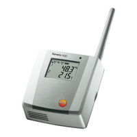
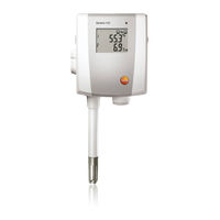
Saveris H4E Ethernet probe
TESTO Saveris H4E Ethernet probe Manuals
Manuals and User Guides for TESTO Saveris H4E Ethernet probe. We have
2
TESTO Saveris H4E Ethernet probe manuals available for free PDF download: Instruction Manual, Commissioning Instructions
TESTO Saveris H4E Ethernet probe Instruction Manual (178 pages)
Measurement data monitoring with testo Saveris Small Business Edition
Brand:
TESTO
| Category:
Measuring Instruments
| Size: 10 MB
Table of Contents
1 Contents
3
Table of Contents
3
2 Safety and the Environment
7
About this Document
7
Ensure Safety
8
Protecting the Environment
8
3 Specifications
9
Use
9
System Requirements
10
4 Product Description
12
Saveris Base
12
Saveris Base GSM Module (Optional)
14
Control Keys
14
Displays
15
Save Radio Probe
21
Radio Probe Without Display
21
Radio Probe with Display
22
Meaning of the LED Displays at the Probes
23
Saveris Ethernet Probes
24
Saveris Router
26
Saveris Converter
27
Saveris Analog Coupler
28
5 First Steps
29
Flowchart
29
Inserting SIM Card (Optional)
31
Connecting USB Cable to the Saveris Base (Optional)
32
Connecting GSM Antenna (Optional)
33
Connecting Saveris Base with Power Supply
34
Power Supply Via Mains Unit
34
Power Supply Via Plug-In/Screw Connection (Optional)
35
Inserting Batteries in the Probes
36
Connecting Radio Probe
37
Installing Saveris Software
39
Starting up Hardware
40
Starting Saveris Software
42
Expand Measuring System
44
Integrating a Saveris Router (Optional)
44
Connecting Router with Power Supply (Mains Unit)
45
Connecting Router with Power Supply (AC/DC)
46
Connecting Router
48
Assigning Probes
51
Connecting Routers in Series
53
Assigning an IP Address to the Saveris Base (Optional)
57
Integrating Saveris Ethernet Probe (Optional)
58
Connecting the Network Cable
59
Connecting Ethernet Probe with Power Supply (Mains Unit)
60
Connecting USB Cable and Installing Driver (Optional)
61
Assigning Connection Data
62
Connecting the Network Cable to the Saveris Base
64
Starting up Ethernet Probes
65
Integrating Saveris Converter (Optional)
69
Integrating Saveris Analog Coupler (Optional)
70
Performing the Test Run
77
Checking System Availability
77
Testing the System
78
Checking Alarm Chain
79
Mounting the Hardware
79
Mounting the Saveris Base on the Wall
80
Setting up Saveris Base with Stand
82
Mounting the Probe on the Wall
83
Checking the Measuring System Again
84
6 Using the Product
85
User Interface
85
Menus and Commands
87
Start
87
Edit
88
Options
90
Axes
93
Template
93
Selecting Projects
93
Style Template
93
Creating, Editing and Deleting Zones
94
Creating Zones
94
Change Zones
95
Deleting Zones
95
Configuring the Alarms
95
Basic Settings for the SMS Messages
96
Setting up Base Alarms
98
Setting up Alarm Groups
99
Components
99
Channels
101
Analyzing Series of Measurements
104
Diagram View
104
Enlarging the View
104
Information on a Reading (Crosshairs)
104
Showing Regression Curve
105
Text Field
105
Characteristics of a Curve
106
Settings for the Axes in the Diagram
110
Marking Readings
113
Table View
113
Dropping the Marking
114
Inserting Extreme Values or Mean in the Table
114
Compressing Readings
114
Dropping Compression
115
Determining Largest Reading
115
Determining the Smallest Reading
115
Add Rows
115
Compress
116
Drop Compression
116
Analyzing Alarms
116
Checking Alarms
116
Acknowledge the Alarm
117
Creating Evaluations
118
Printing Measurement Data
118
Archiving with Automatic Reports
119
Checking the Database Capacity
119
System Settings
121
General Settings for the Saveris Base
121
Show Operating Data of the Probes
122
Settings for the Radio Probe
123
Ethernet Probes
125
Analog Coupler
127
Report Settings
128
7 Maintaining the Product
131
Maintenance
131
Replacement of Components
131
Deleting Components
131
Adding New Components
134
Logging Components Back in
138
Calibration and Adjustment
140
On-Site Calibration and Adjustment
141
External Calibration and Adjustment
141
Saving Data in the Saveris Base
142
Restarting the Saveris Base
143
Removing Probe from Wall Bracket
144
Changing Batteries at Probe
144
Changing a Battery
146
Carrying out a Software and Firmware System Update
148
Carrying out a Software Update
149
Uninstalling Software
149
Software Installation
149
Carrying out a Firmware System Update
150
Technical Data
153
Saveris Base
153
Saveris Radio Probe
154
Saveris Router
161
Saveris Ethernet Probes
162
Saveris Converter
168
Saveris Analog Coupler
169
8 Tips and Assistance
172
Questions and Answers
172
Saveris Base Alarm Messages
172
Accessories and Spare Parts
173
Advertisement
TESTO Saveris H4E Ethernet probe Commissioning Instructions (120 pages)
Measurement data monitoring system
Brand:
TESTO
| Category:
Measuring Instruments
| Size: 5 MB
Table of Contents
Table of Contents
3
1 About this Document
7
Symbols and Writing Standards
7
Warning Notices
8
2 Safety and Disposal
8
Safety
8
Batteries
9
3 Protecting the Environment
9
4 Support
9
5 Commissioning Instructions
10
System Requirements
10
Computer
10
Operating System and Database
10
Network Environment
12
WLAN-Specific Data
12
Technical Data for a Secure WLAN
12
6 Commissioning
13
Flowchart: Configuration for Monitoring Stationary Zones
13
Flowchart ("Mobile Monitoring"): Configuration for Transport Monitoring with Saveris Radio Data Loggers
15
Commissioning the Saveris Base
17
Inserting SIM Card (Optional)
17
Connecting Network Cable to the Saveris Base
18
Connecting GSM Antenna (Optional)
19
Connecting Saveris Base to Power Supply
19
Power Supply Via Mains Unit
19
Power Supply Via Plug-In/Screw Connection (Optional)
20
Connecting USB Cable (Optional)
21
Assigning an IP Address to the Saveris Base (Optional)
22
Commissioning of Radio Data Loggers in Testo Saveris
23
Inserting Batteries into Saveris Radio Data Logger
23
Registering Saveris Radio Data Loggers in the System
24
BT Gateway for Testo 182
26
Equipment Required
26
Establishing Connections to the Gateway
26
Configuring the BT Gateway for Testo 182
27
Configuring Operation Via WLAN
28
Configuring Operation Via Ethernet / LAN
29
Configuring the AWS Bucket
29
Carrying out Firmware Updates
30
Commissioning Testo Saveris Software
30
Installing Testo Saveris Software
30
Installing Saveris Mail Services
31
Installing MAPI Mail
31
Installing SMTP Mail
33
Installing Testo Saveris CFR Transport Add-On
34
Initial Commissioning of the Hardware
35
Configuring Hardware
41
Integrating Testo Saveris 2 H2 WLAN Data Logger
43
Integration of Ethernet Data Loggers into Testo Saveris (Optional)
45
Connecting Network Cable
45
Connecting Testo Saveris Ethernet Data Logger to Power Supply (Mains Unit)
46
Connecting USB Cable and Installing Driver (Optional)
47
Integrating Testo Saveris Analog Coupler (Optional)
48
Integrating Testo Saveris Transmitter
52
Integrating Testo Saveris Router (Optional)
52
Connecting Testo Saveris Router to Power Supply (Mains Unit)
53
Registering Testo Saveris Router
55
Assigning Data Loggers
56
Connecting Saveris Routers in Series
58
Integrating Saveris Converter (Optional)
61
Integrating Saveris Extender
61
Integrating Saveris Cockpit Unit (Optional)
62
Registering Saveris Cockpit Unit
63
Fitting Saveris Cockpit Unit in the Driver's Cab and Connecting It to a Power Supply
65
Installation of the Components
66
Mounting the Saveris Base on the Wall
66
Setting up Saveris Base with the Stand
67
Wall Mounting of Data Loggers
68
Wall Mounting of T1/T1D/T2/T2D/Pt/Ptd/H4D Radio Data Loggers
68
Wall Mounting of Testo Saveris 2 H2 WLAN Data Loggers
70
BT Gateway for Testo 182 Wall Mounting
70
Removing Components from the Wall Bracket
72
Checking the Measurement System Again
72
Performing Test Run
73
Checking System Availability
73
Performing System Test
74
7 Maintenance
75
Data Backup
75
Creating Backup
75
Automatic Backup of the Saveris Data
75
Manual Backup of the Saveris Data
75
Testo Saveris Base Backup
76
Checking the Database Capacity
77
System Settings
77
Replacing Components
80
Deleting Components
80
Adding New Components
81
Re-Registering Components
85
Calibration and Adjustment
86
On-Site Calibration and Adjustment
86
External Calibration and Adjustment
86
Changing Batteries
87
Changing the Saveris Base Batteries
87
Changing the Saveris Radio Data Logger Batteries
88
Changing the Saveris Ethernet Data Logger / Saveris Analog Coupler Batteries
90
Update
91
Carrying out Software Update
91
Uninstalling Software
92
Installing Software
92
Installing Server
92
Performing Firmware System Update
93
Carrying out a Testo Saveris Cockpit Unit Firmware Update
95
8 Technical Data
97
Testo Saveris Base
97
Radio Data Loggers for Testo Saveris
98
General
98
Testo Saveris T1 / T1D
98
Testo Saveris T2 / T2D
99
Testo Saveris T3 / T3D
100
Testo Saveris Pt / Ptd
100
Testo Saveris H3 / H3D
101
Testo Saveris H2D
102
Testo Saveris H4D
102
Testo Saveris 2 H2
102
Ethernet Data Loggers for Testo Saveris
104
General
104
Testo Saveris Pte
105
Testo Saveris T1E
105
Testo Saveris H4E
106
External Probes
106
Testo Saveris T4E
107
Testo Saveris H2E
107
Testo Saveris H1E
108
Analog Couplers for Testo Saveris
109
Saveris Wireless Analog Coupler U1
109
Saveris Ethernet Analog Coupler U1E
110
Transport Data Loggers for Testo Saveris
111
Testo 182 - BT Transport Data Logger
111
Testo 184 · USB Transport Data Logger
111
Testo Saveris Router
113
Testo Saveris Converter
114
Testo Saveris Extender
114
BT Gateway for Testo 182
115
Testo Saveris Cockpit Unit
116
Advertisement
Related Products
TESTO Saveris H1
TESTO Saveris H2
TESTO Saveris H3 radio probe
TESTO Saveris H3D radio probe
TESTO Saveris H4D radio probe
TESTO Saveris H2D radio probe
TESTO H2E Ethernet probe
TESTO H1E Ethernet probes
TESTO Saveris PtE Ethernet probe
TESTO Saveris T1E Ethernet probe
TESTO Categories
Measuring Instruments
Thermometer
Data Loggers
Test Equipment
Thermal cameras
More TESTO Manuals
Login
Sign In
OR
Sign in with Facebook
Sign in with Google
Upload manual
Upload from disk
Upload from URL