TESTO Saveris Instruction Manual
Measurement data monitoring system, saveris professional edition v4.6 sp1
Hide thumbs
Also See for Saveris:
- Instructions manual (222 pages) ,
- Instruction manual (178 pages) ,
- User manual (164 pages)

Related Manuals for TESTO Saveris


Summary of Contents for TESTO Saveris
- Page 1 Measurement data monitoring system: testo Saveris Software: testo Saveris Professional Edition V4.6 SP1 Instruction manual...
-
Page 3: Table Of Contents
Saveris radio data logger without display ..............21 Saveris radio data logger with display ................ 22 6.3.2 6.3.2.1 Displays ..........................23 testo Saveris radio data logger LED status displays ..........23 6.3.3 testo Saveris 2 H2 ....................24 6.4.1 Short description ......................24 Display and control elements .................. - Page 4 Control keys ....................... 33 6.10.3 6.10.4 Displays ........................33 Using the product ................38 Starting the Saveris software ................38 Use of testo Saveris software for monitoring in the stationary area ....38 General ........................38 7.2.1 User interface ......................39 7.2.2 7.2.3 Menus and commands ....................
- Page 5 Contents Use of testo Saveris software for transport monitoring with radio data loggers (“mobile monitoring”) ................... 84 7.3.1 General ........................84 Setting up tours ......................85 7.3.2 Tour description........................85 7.3.2.1 Planning tours ........................86 7.3.2.2 7.3.2.3 Defining tours ........................87 7.3.2.4...
-
Page 7: About This Document
1 About this document 1 About this document • The instruction manual is an integral part of the testo Saveris measurement data monitoring system. • Keep this documentation to hand so that you can refer to it when necessary. •... -
Page 8: Warning Notices
Always operate the product properly, for its intended purpose and within the parameters specified in the technical data. Do not use any force. • Never use the Saveris probes to measure on or near live parts. • Only carry out maintenance and repair work on the components of the testo Saveris measurement data monitoring system that are described in the documentation. -
Page 9: Batteries
Do not store the product together with solvents. Batteries The batteries in the Saveris base, the Saveris Ethernet data loggers and the Saveris analog couplers are wearing parts which have to be replaced after approx. 2 years. If batteries are faulty, it is not possible to guarantee full operability of the GSM module. -
Page 10: How It Works
(or also directly) to the Saveris base as soon as there is an adequate radio link. The Saveris cockpit unit can be used in the truck for direct checking of readings. If radio data loggers are registered in mobile zones, all the radio data loggers are in one radio cell on the same channel. -
Page 11: Exclusion Of Liability
Liability on the part of Testo SE & Co. KGaA for damages from this type of application is excluded. - Page 12 Ethernet testo Saveris converter signal. This combines the flexible connection of the Saveris radio data logger with use of the existing Ethernet, even over long transmission paths. By connecting a Saveris extender to an...
-
Page 13: Testo Saveris Base
6 Product description testo Saveris base Front 6.2.1 Display for the visualization of alarms and user guidance Antenna Warning LED Keypad for operation of the Saveris base LED for status display... -
Page 14: Rear
6 Product description Rear 6.2.2 USB cable connection Network cable connection Power supply connection via mains plug Power supply connection via 24 V AC/DC and alarm relay Connection for external GSM antenna Eyelets for strain relief Guide for stand or wall bracket... -
Page 15: Underside
[Esc] twice: shuts down the Saveris base press and hold down [Esc]: starts up the Saveris base [Enter] Starts the login status for the Saveris radio data loggers in the Info System menu. [ ▲ [ ▼ ] Navigation keys for changing the menus. - Page 16 The IP address is the unique identification number of the Saveris base within the network Netmask which is saved in the Saveris base. The netmask is the basic address of the network which the Saveris base is integrated into. Gateway which is saved in the Saveris base.
- Page 17 6 Product description Alarm detail menu Date on which the alarm was triggered. Time at which the alarm was triggered. Probe for which the alarm was triggered. Alarm number and total number of alarms. Keys that are assigned functions in this menu. Detail meas.
- Page 18 Type designation of the registered instrument. Radio quality: Radio quality of the registered instrument (does not apply to Saveris Ethernet data loggers and Saveris extender). Battery: Battery status of the instrument (does not apply to Saveris extender, Saveris converter and Saveris cockpit unit).
- Page 19 Number of registered instruments. Keys that are assigned functions in this menu. Info System menu Probe: Number of registered Saveris radio data loggers. Probe: Number of registered Saveris Ethernet data loggers. Router Converter: Number of registered Saveris routers. Router Converter: Number of registered Saveris converters.
- Page 20 6 Product description Login 1/2 (Login) menu Status display when registering data loggers. Login 2/2 (Login) menu Keys that are assigned functions in this menu. Login time exceeded Cancel ENTER New try This display is shown if no registration signal has been received from a data logger within approx.
-
Page 21: Radio Data Logger For Testo Saveris
Antenna for radio transmission of measurement data to the Saveris base. Guide rails for the wall bracket. Catch for the wall bracket. Ports, depending on the type. Connect key for registering the probe on the Saveris base and for a status request during operation. -
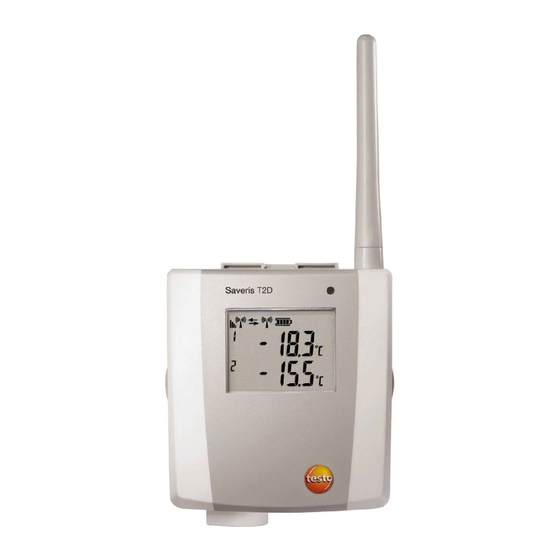
Page 22: Saveris Radio Data Logger With Display
Antenna for radio transmission of measurement data to the Saveris base. Guide rails for the wall bracket. Catch for the wall bracket. Ports, depending on the type. Connect key for registering the Saveris data logger on the Saveris base and for a status request during operation. -
Page 23: Displays
6 Product description Displays 6.3.2.1 Quality of the radio link. Indicator as to whether a communication with the Saveris base or a Saveris router or Saveris converter is being carried out. Status of batteries. Unit of the reading: for humidity measurement for current measurement °Ctd... -
Page 24: Testo Saveris 2 H2
6 Product description Status displays during operation Briefly press the connect key on the rear of the data logger once and the LED shows the status of the connection to the Saveris base. Display Explanation Flashing 3 x green There is a very good connection to the Saveris base. -
Page 25: Display And Control Elements
External power supply (via USB port) WLAN signal strength 100% WLAN signal strength 75% WLAN signal strength 50% WLAN signal strength 25% There is a data connection to the Saveris base, icon flashes: data connection to testo Saveris is being established. -
Page 26: Ethernet Data Logger For Testo Saveris
Measurement channel 1 Measurement channel 2 Alarm status: upper limit value overshot Alarm status: lower limit value undershot Ethernet data logger for testo Saveris Display for showing readings and transmission information. LED for status display. Connect key. Catch for the wall bracket. - Page 27 6 Product description Input for power supply via mains unit. Displays Status of batteries Indicator as to whether a communication with the Saveris base is being carried out. Unit of the reading: for humidity measurement for current measurement °Ctd °Ftd for dewpoint measurement.
-
Page 28: Saveris Wireless Analog Coupler
Only with wireless analog coupler U1: antenna for sending the measurement data. LED for status display. Connect key for registering the wireless analog coupler on the Saveris base and for a status request during operation. Catch for the wall bracket. -
Page 29: Testo Saveris Router
Saveris router Antenna for radio transmission of the measurement data. LED for status display. Connect key for registering the Saveris router on the Saveris base and for a status request during operation. Catch for the wall bracket. Guide rails for the wall bracket. -
Page 30: Testo Saveris Converter
Saveris converter Antenna for radio transmission of the measurement data. LED for status display. Connect key for registering the Saveris router on the Saveris base and for a status request during operation. Catch for the wall bracket. Guide rails for the wall bracket. -
Page 31: Testo Saveris Extender
Input for connecting the network cable (optional power supply via PoE). Input for service interface Input for power supply via mains unit Component is only permitted for mobile monitoring in all countries with a radio frequency of 868 MHz. Saveris extender cannot be operated via VPN. -
Page 32: Testo Saveris Cockpit Unit
6.10 testo Saveris cockpit unit 6.10.1 Front Display for the visualization of alarms and user guidance Warning LED and PC interface Keypad for operating the Saveris cockpit unit 6.10.2 Rear Mini USB cable connection Guide for bracket Component is only permitted for mobile monitoring in all countries with a radio frequency of 868 MHz. -
Page 33: Control Keys
Saveris extender/Saveris base Feedback informing the driver that a Saveris data logger of the selected tour contains measurement data that have not yet been transferred to the Saveris base. The symbol only appears after a second measuring cycle or 30 minutes. - Page 34 6 Product description Device settings menu Sub-menus: • Day/night settings • Illumination • Reading display settings • Factory reset Alarm menu Description of why an alarm has been triggered. Channel name (Probe): Data logger which the alarm was triggered for. Date: Date on which the alarm was triggered.
- Page 35 6 Product description Min/Max menu Data logger and associated mobile zone for which the reading was transferred. Min. reading with associated unit. Max. reading with associated unit Keys that are assigned functions in this menu. Tour settings (Tour)menu Selection of the first mobile zone (with [ ▲...
- Page 36 Selection of the output type. Keys that are assigned functions in this menu. The print data can be sent via infrared to the Testo printer 0554 0549. Login 1/2 menu Status display when the Saveris cockpit unit is registering on the Saveris...
- Page 37 6 Product description Login 2/2 menu Login time exceeded This display appears when the Saveris cockpit unit was unable to register on the Saveris base within approx. 30 seconds. Keys that are assigned functions in this menu. Login time exceeded...
-
Page 38: Using The Product
It can take a few minutes for the first readings to be displayed. Use of testo Saveris software for monitoring in the stationary area General 7.2.1 The following section deals with the functionality of the testo Saveris software which is relevant for measurement data monitoring in closed areas (production plants, warehouses). -
Page 39: User Interface
7 Using the product User interface 7.2.2 In this section, you will find out how the user interface of the Saveris software is designed. 1 Menu bar Display area The readings are represented in the display area as diagrams and tables, as well as the alarms received being listed. -
Page 40: Menus And Commands
7 Using the product Menus and commands 7.2.3 In this section, you find out which menus and commands are available to you and what you can use these commands for. Start 7.2.3.1 Start Clipboard menu Menu functions Description Copy Copies the marked element onto the clipboard. - Page 41 7 Using the product Menu functions Description Offline The measurement is performed with a time delay, meaning that the data that are called up are not automatically updated. The data will not be called up by the base until you are actively working in the software, e.g.
-
Page 42: Edit
7 Using the product Notes menu Start Menu functions Description Insert Adds a free comment text to a desired channel at a point in time that can be selected. The note can be seen in the Graphic view as a yellow icon and as a red triangle in the table cell in the Table view. - Page 43 7 Using the product Menu functions Description Crosshairs Crosshairs which can be used to follow the curve are shown by clicking on a point of a measurement curve. The date, time, reading number and reading are shown in the process. Regression curve Regression curves are an aid to enabling better evaluation of large,...
- Page 44 7 Using the product Menu functions Description Edit formula Allows an existing formula to be edited. Delete formula Deletes an existing formula. Edit Tools menu (table) Menu functions Description Mark Marks data over a definable time period or definable rows (index range).
- Page 45 7 Using the product Edit in the monitor view Edit menu (monitor) is only displayed if the diagram window has been activated by clicking on the window. Edit Tools menu (monitor) Menu functions Description Wallpaper Opens the Open dialogue to select the wallpaper for the monitor.
-
Page 46: Axes
7 Using the product You can adjust the number fields as required using the right mouse button. You can thus show or hide their frames or their transparency, for example. You can move the fields and change their size with the left mouse button. -
Page 47: Service
7 Using the product Service 7.2.3.5 Service Service menu This menu can be used to display the service data. Menu function Description Display service data Creates an *.html file with the service data. The software version number can be found under service data. - Page 48 7 Using the product In the tree structure of the data area, open the group that contains the data to be displayed. The data for the selected data is displayed. If necessary, deactivate channels via the checkboxes for the display.
- Page 49 7 Using the product Showing regression curve Place a regression curve over the diagram to show the course that the measurement series tends to take. Click on Edit Tools Regression curve. Click on the reading curve for which the regression curve needs to be shown.
- Page 50 7 Using the product Edit line Name Explanation Smooth The measuring points are connected by an interpolated curve; that is, the plot-points on the curve between two measuring points are estimated mathematically. Mark measuring points The individual measurement points are represented by a symbol. The value shown exactly corresponds to the measured value only at these points.
- Page 51 7 Using the product Range limits Name Explanation Display range limits Specification as to whether the limit values should be shown in the diagram. Add limit labels Specification as to whether the limit values should be labelled (Upper/Lower limit value: name of curve).
- Page 52 7 Using the product Statistical computation Name Explanation Min. value Smallest reading of the curve. Max. value Largest reading of the curve. Mean value Arithmetically-determined average reading. Std. deviation Measure of the scattering of the readings around the mean value. Criteria Setting display criteria: all, date/time and index range.
- Page 53 7 Using the product Name Explanation Division linear Specification that the axes are divided in a linear manner. Division logarithmic Specification that the axes are divided logarithmically, meaning the division increments represent powers of ten. [OK] Applies the settings until other data are called up.
- Page 54 7 Using the product Name Explanation [OK] Applies the settings until other data are called up. The dialogue is closed. [Cancel] Closes the dialogue without applying any changes at all. Position Shows a freely-definable extract of the diagram. Automatic scaling... Shows the entire diagram in the window.
-
Page 55: Table View
7 Using the product Table view 7.2.4.2 The readings are listed in table form in this view. In the Start View menu, the Table command is activated. You now have to select the data record that you wish to display. In the calendar, select the day or time period that needs to be evaluated. - Page 56 7 Using the product The dialogue is closed and the corresponding readings in the table are marked. The selected readings can be copied and further edited using suitable software (e.g. with Microsoft Excel ® ® Dropping marking Click on Edit Tools Drop...
- Page 57 7 Using the product At least one of these values must be activated to enable compression of the table to be carried out. Enter the time span under Extract and determine its unit. Possible settings for the unit: • (second) •...
-
Page 58: Floorplan View
7 Using the product The table is again displayed with all the individual values. Determining the smallest reading In the Edit Search Minimum menu, click on the curve for which the smallest reading needs to be determined. The smallest reading is displayed as marked in the table. Floorplan view 7.2.4.3 The readings are shown as number fields in this view. -
Page 59: Archiving With Automatic Reports
Template Template menu, select the types of report header. Via the File (Testo logo) | Page view command, open a preview of the report. Use portrait format for printing a table, but landscape format is recommended for printing a diagram. -
Page 60: Creating Automatic Reports
7 Using the product Creating automatic reports 7.2.4.8 Use the One-off report function to generate 21 CFR 11-compliant printouts of any period of time. Select Stationary zones main menu. Mark required time period on the calendar. In the Start tab under Create reports, click on One-off... -
Page 61: Configuring Automatic Reports
7 Using the product Configuring automatic reports 7.2.4.9 In the report settings, you can determine how automatic reporting should be done. Automatic reports. In the navigation area, click on Settings for automatic reports submenu is displayed in the data window. - Page 62 7 Using the product Name Explanation Report schedule Specify whether the report is to be generated daily, weekly, monthly at a custom time. Daily: The report is generated daily at 1 a.m. Weekly: The report is generated every Sunday at 1 a.m.
-
Page 63: Managing Zones
Managing zones 7.2.5 Once you have familiarized yourself with the menus of the Saveris software, you can turn to creating zones, for example to separate the data loggers according to location. You could perhaps combine data loggers that are located in storerooms into one zone and data loggers that are located in refrigerated rooms into another. -
Page 64: Changing Zones
7 Using the product In the Name field, enter the name of the new zone. Assign names for the zones that are not longer than 15 characters. Confirm entries with [OK]. New zone dialogue is closed and the new zone is listed in the tree structure in the data area. -
Page 65: Assigning Zones
7 Using the product In the database, the zone is marked as deleted and disabled, but not deleted. A disabled zone is only visible in the time period in which it was active. Assigning zones 7.2.5.4 You can limit zone access to certain users and user groups. Multiple selection is also possible. -
Page 66: Configuring Alarms
Information on the alarm function • The alarms occurring in the Saveris system are primarily used to notify the user in good time that problems have occurred which jeopardize the continuous availability of the data in the database. Generally, action is then required. -
Page 67: Setting Up Saveris Base Alarms
7 Using the product Setting up Saveris base alarms 7.2.6.1 No configuration changes are transferred to the probe/base until you Alarm management have exited the menu! You should therefore exit the Alarm management menu after any changes. Alarm management Click on in the navigation area. - Page 68 7 Using the product Display Explanation Device alarm Saveris Base Setting options for the Saveris base alarms No PC connection: no response from the PC. Memory almost full: alarm when the Saveris base memory overflows. No GSM Network: alarm when there is no GSM connection.
-
Page 69: Setting Up Time Control
7 Using the product Setting up time control 7.2.6.2 All alarms across the entire system are paused/activated via time control. Click on Enable time control. Alarm time control button is activated. Click on Alarm time control. An input window with a complete time control system is displayed. The time control is filled out from Monday to Sunday 0:00 –... -
Page 70: Setting Up Alarm Groups
The input window is closed and the modifications to the time control are accepted. Setting up alarm groups 7.2.6.3 Component alarms No configuration changes are transferred to the Saveris radio data Alarm management logger/Saveris base until you have exited the menu! Alarm management... - Page 71 System alarms: alarm activation for notification when there are connection problems, LoBat and power failure Alarm conditions: trigger acknowledged alarms after [min] Alarm output Saveris base: settings for relays, audible signal and light signal. [Apply settings] Saves the alarm settings of an alarm...
- Page 72 The assigned alarm group is deleted, all components that were assigned to this group are now without an alarm group. Channel alarms No configuration changes are transferred to the Saveris data Alarm management logger/Saveris base until you have exited the...
- Page 73 • Comments for acknowledging alarms Alarm settings channel. Click on The alarm settings for Saveris data loggers are shown in the display area. Name Description Insert into new group Creates a new alarm group, with a distinction between alarm, warning and trend alarm group.
- Page 74 [Apply settings] Saves the alarm settings of an alarm group. [Print] Creates a file containing a summary of the alarm settings for Saveris probes and the Saveris base. Create new group Right-click on component, then click on [Insert into new group].
-
Page 75: Creating Recipient
The assigned alarm group is deleted, all components that were assigned to this group are now without an alarm group. Creating recipient 7.2.6.4 No configuration changes are transferred to the Saveris data Alarm management logger/Saveris base until you have exited the menu! - Page 76 7 Using the product Name Description [New recipient] Creates a new entry in the recipient list. Recipient list List of possible recipients. The telephone number in the recipient list comes from commissioning. You can replace the number with a recipient name by clicking on the number with the right mouse button and Rename...
- Page 77 7 Using the product Name Description Readiness Overview of the recipient’s availability times. Time entries are automatically rounded up/down to 1/4 hour. To change the availability time, you must delete the existing entry using the right mouse button and enter a new availability time.
-
Page 78: Creating Alarm Rule
You should therefore exit the Alarm management menu after any changes. A prerequisite for creation of alarm rules is that the Saveris base alarm settings, the alarm groups of the Saveris probes and the recipients of the alarm messages have been entered. Click on Alarm management in the navigation area. - Page 79 7 Using the product Name Description Group Group for which the alarm rule applies. Recipient Recipient who is to receive the alarm message. Message Text of the alarm message. Forward after Time period after which the alarm message needs to be sent to another recipient if the first recipient does not acknowledge the alarm.
- Page 80 7 Using the product Name Description To 3rd recipient Recipient who is to receive the forwarded alarm message if the alarm was not acknowledged. [New rule…] Starts the wizard for creating a new alarm rule. Preview Shows the configured scheduled messages.
- Page 81 7 Using the product The dialogue for the forwarding function or for finishing the alarm rule is shown. Either click on [Finish], when the alarm message does not need to be forwarded if the first recipient does not acknowledge the alarm [Finish] is only displayed if no forwarding is needed.
- Page 82 7 Using the product The dialogue for the forwarding function or for finishing the alarm rule is shown. Either 10.1 click on [Finish], when the alarm message does not need to be forwarded if the alarm is not acknowledged ...
-
Page 83: Alarm Overview
7 Using the product Alarm overview 7.2.6.6 In the alarm overview you will find a list of the groups with their specific alarm settings. Click on Alarm management in the navigation area. The following submenus are displayed in the data area: •... -
Page 84: Use Of Testo Saveris Software For Transport Monitoring With Radio Data Loggers ("Mobile Monitoring")
(“mobile monitoring”) General 7.3.1 The following section deals with the relevant functionality of the testo Saveris software for measurement data monitoring in terms of transport monitoring using Saveris radio data loggers (“mobile monitoring”), see also section 5.2 How it... -
Page 85: Setting Up Tours
Tour management. Tour description dialogue is displayed in the data area. Select [New tour description]. Enter the name of the new tour description. The name appears in the tour calendar and in the Saveris cockpit unit. Enter information. -
Page 86: Planning Tours
The tour description is saved and can be added to a tour during tour planning. The tour description is transferred to the Saveris cockpit unit and can be selected there. The Saveris cockpit unit can manage up to 100 tour descriptions. -
Page 87: Defining Tours
7 Using the product Select mobile zones. If required: add tour description. Select time period during which the tour is to be carried out. Exit dialogue. Query appears asking whether information should be saved. Click [Apply settings]. The tour is saved and is displayed in the tour calendar as a planned tour. -
Page 88: Displaying Tours
Adjustable filter options • Calendar view • Overview of the tours that have taken place and status of data transfer to the Saveris base: Green: Data transfer complete Yellow: Data transfer in progress Red: Data transfer failed • Planned tours are shown in white •... -
Page 89: Searching For Tours
7 Using the product Searching for tours 7.3.2.5 In the navigation area, click on Tour management. Tour finder. Select Select or enter required search options. When searching for tours within a time frame, the tour is considered as a whole. No result is shown if only one part of the tour is within the time frame specified in the search. -
Page 90: Tips And Assistance
The Saveris converter checks its configuration and if there is an error, it resets all values to the factory settings. Saveris cockpit unit does not The power supply to the Saveris cockpit unit print. has been interrupted. • Restore the power supply to the Saveris cockpit unit. - Page 91 - Check in the startup wizard whether the L_RF2010StreamRip extreme SMS gateway is enabled. L_UDPRF2010 - Reboot the Saveris base. If there are problems, please contact our support team. - Option 2 - Restart the base. If the problem persists, please contact our support team.
-
Page 92: Accessories
10°C (Energizer L91 photo lithium) Spare rechargeable battery for Saveris base, Ethernet 0515 5021 probe and analog coupler 100-200 V DC mains unit; for Saveris base, router, 0554 1096 converter, Ethernet probe Mains unit (top-hat rail mounting) 90 to 240 VAC / 24 0554 1749 VDC (2.5 A) - Page 93 8 Tips and assistance Description Order no. ISO temperature calibration certificate; temperature 0520 0151 probe; calibration points -18°C, 0°C, +60°C; per channel/instrument (not suitable for Saveris T1/T2) DAkkS temperature calibration certificate; temperature 0520 0261 probe; calibration points -20°C, 0°C, +60°C; per channel/instrument ISO humidity calibration certificate;...
- Page 94 Testo SE & Co. KGaA Testo-Strasse 1 D-79853 Lenzkirch Germany Phone: +49 7653 681-0 Fax: +49 7653 681-7699 Email: info@testo.de www.testo.com 0970 4030 en 14 V04.6-SP1...
Need help?
Do you have a question about the Saveris and is the answer not in the manual?
Questions and answers
What does Err 0002 mean when displayed on the screen.