TESTO Saveris Instructions Manual
Professional edition measurement data monitoring
Hide thumbs
Also See for Saveris:
- Instruction manual (178 pages) ,
- User manual (164 pages) ,
- Quick start manual (2 pages)

Related Manuals for TESTO Saveris


Summary of Contents for TESTO Saveris
- Page 1 Measurement data monitoring with testo Saveris Professional Edition Instruction manual...
-
Page 3: Table Of Contents
Flow chart (Saveris mobile) ............40 5.3. Inserting SIM card (optional) ............42 5.4. Connecting the network cable to the Saveris base ......43 5.5. Connecting GSM antenna (optional) ..........44 5.6. Connecting Saveris base with power supply ......... 45 5.6.1. - Page 4 5.14.7. Integrating a Saveris cockpit unit (optional) ........... 87 5.14.7.1. Registering a Saveris cockpit unit ............ 88 5.14.7.2. Fitting a Saveris cockpit unit in the driver's cab and connecting to a power supply ................... 89 5.14.8. Integrating Saveris analog coupler (optional) ..........91 5.15.
- Page 5 1 Contents 6.3. Creating, editing and deleting zones ........... 117 6.3.1. Creating zones ..................... 117 6.3.2. Changing zones ................... 118 6.3.3. Deleting zones ..................... 118 6.3.4. Assigning zones ................... 118 6.4. Setting up tours ................119 6.4.1. Tour description ................... 119 6.4.2.
- Page 6 7.9.1.3. Installing the server ............... 191 7.9.2. Carrying out a firmware system update ............191 7.9.3. Carrying out a Saveris cockpit unit firmware update ........194 7.10. Technical data ................195 7.10.1. Saveris base ....................195 7.10.2. Saveris radio probe ..................196 7.10.3.
-
Page 7: Safety And The Environment
Pos: 4 /TD/Überschriften/2.1 Zu diesem Dokument @ 0\mod_1173775252351_79.docx @ 346 @ 2 @ 1 2.1. About this document Pos: 5 /TD/Sicherheit und Umwelt/Zu diesem Dokument/Symbole und Schreibkonventionen/Symbole und Schreibkonv. [Saveris] @ 0\mod_1193735939953_79.docx @ 5623 @ 5 @ 1 Symbols and writing standards Representat... -
Page 8: Ensure Safety
2.2. Ensure safety Pos: 8 /TD/Sicherheit und Umwelt/Sicherheit gewährleisten/Saveris spannungsführende Teile @ 1\mod_1204907008625_79.docx @ 12630 @ @ 1 > Never use the Saveris probes to measure on or near live parts. Pos: 9 /TD/Sicherheit und Umwelt/Sicherheit gewährleisten/Saveris Wartungsarbeiten @ 1\mod_1196958627509_79.docx @ 6094 @ @ 1 >... -
Page 9: Specifications
Specifications Pos: 16 /TD/Überschriften/3.1 Verwendung @ 0\mod_1176211016437_79.docx @ 695 @ 2 @ 1 3.1. Pos: 17 /TD/Leistungsbeschreibung/Verwendung/testo Saveris/01 Einsatzgebiete Transport @ 7\mod_1291125156091_79.docx @ 73886 @ 5 @ 1 Areas of application The testo Saveris measurement system can be used anywhere... - Page 10 HGV If radio probes are registered in mobile zones, all these probes are in one radio cell on the same channel. The Saveris extenders work as external distributed antennas of the Saveris base. All of these radio probes are registered on the Saveris base.
-
Page 11: System Requirements
If you have any queries or problems, please contact Testo Customer Service. Contact data see back of this document or website www.testo.com/service-contact. Pos: 21 /TD/Leistungsbeschreibung/Verwendung/testo Saveris/04 Haftungsausschluss @ 1\mod_1197376616906_79.docx @ 6214 @ 5 @ 1 Exclusion of liability The testo Saveris system was developed to consolidate a large... - Page 12 The Microsoft® versions SQL Server 2008, 2012, 2014 and Terminal Server are supported. Pos: 25 /TD/Leistungsbeschreibung/Systemvoraussetzungen/Firewall-Hinweis (Saveris Prof) @ 2\mod_1217489598125_79.docx @ 19983 @ @ 1 In client-server operation, we recommend a network with AD and DNS (Domain Name System) to enable online ®...
- Page 13 In combination with virtual systems, a USB connection works unreliably, which is why we recommend connecting the base via Ethernet. Pos: 26 /TD/Leistungsbeschreibung/Systemvoraussetzungen/Akku-Info (Saveris) @ 14\mod_1373268824588_79.docx @ 171823 @ 5 @ 1 Rechargeable battery The battery in the Saveris base, the Ethernet probes and the analog coupler is a wearing part, which has to be replaced after approx.
-
Page 14: Product Description
Pos: 29 /TD/Produktbeschreibung/Übersicht/testo Saveris/Hinweis CE @ 1\mod_1204905902234_79.docx @ 12612 @ @ 1 As declared in the declaration of conformity, this product complies with Directive 2014/30/EC. Pos: 30 /TD/Produktbeschreibung/Übersicht/testo Saveris/00 Base/01 Base @ 0\mod_1189504245140_79.docx @ 4274 @ 255 @ 1 4.1. Saveris base Front Display for the visualization of the alarms and user guidance. - Page 15 4 Product description Rear USB cable connection. Network cable connection. Connection of power supply via mains plug. Connection of power supply via 24 V AC/DC and alarm relay. Connection for external GSM antenna (only in combination with GSM module). Eyelets for strain relief. Guide for stand or wall bracket.
-
Page 16: Saveris Base Gsm Module (Optional)
4 Product description Pos: 31 /TD/Produktbeschreibung/Übersicht/testo Saveris/00 Base/02 Base GSM @ 1\mod_1196957066669_79.docx @ 6084 @ 2 @ 1 4.2. Saveris base GSM module (optional) Insertion slot for the SIM card. Pos: 32 /TD/Produktbeschreibung/Übersicht/testo Saveris/00 Base/Bedientasten @ 0\mod_1190205422265_79.docx @ 4893 @ 3 @ 1 4.2.1. -
Page 17: Displays
The netmask is the basic address of the network in which the Saveris base is integrated. Address of the gateway saved in the Saveris base. A gateway is a transfer point between networks that work with different protocols or data formats. A "translation" into the respective other protocol or data format is then performed by the gateway. - Page 18 4 Product description Menu Info alarm Number of newly triggered alarms. Keys that are assigned functions in this menu. New alarms have to be checked and acknowledged at regular intervals. A large number (>100) of unacknowledged alarms will impair the system performance.
- Page 19 4 Product description Menu Detail meas. values Probe and channel, if present, for which the measured value was transferred. Measured value with relevant unit. Time at which the measured value was transferred. Date on which the measured value was transferred. Measured value number and total number of measured values.
- Page 20 Radio quality of the successful device (does not apply to Ethernet probes and Saveris extender). Battery status of the device (does not apply to Ethernet probes, Saveris extender and Saveris cockpit unit). Startup indicates whether the device has been configured by the startup wizard.
- Page 21 Info System Number of successful radio probes. Number of successful Ethernet probes. Number of successful routers. Number of successful converters. Number of successful Saveris cockpit units. Number of successful Saveris extenders. Keys that are assigned functions in this menu. Menu Login...
-
Page 22: Saveris Cockpit Unit
Keys that are assigned functions in this menu. This display is shown if no login signal was received from a probe within approx. 30 seconds. Pos: 34 /TD/Produktbeschreibung/Übersicht/testo Saveris/Cockpit Unit Transport/Cockpit Unit @ 7\mod_1291127023702_79.docx @ 74016 @ 255 @ 1 4.3. Saveris cockpit unit... -
Page 23: Control Keys
Before changing the Saveris cockpit unit battery, please contact Testo Customer Service. You can find contact details on the back of this document or at www.testo.com/service-contact Pos: 35 /TD/Produktbeschreibung/Übersicht/testo Saveris/Cockpit Unit Transport/Bedientasten @ 7\mod_1291127031607_79.docx @ 74049 @ 3 @ 1 4.3.1. Control keys Explanation [Enter] •... -
Page 24: Displays
[ ▲ [ ▼ ] Navigation keys to switch the menu or to select an option. Pos: 36 /TD/Produktbeschreibung/Übersicht/testo Saveris/Cockpit Unit Transport/Displayanzeigen @ 7\mod_1291127033232_79.docx @ 74082 @ 35 @ 1 4.3.2. Displays Icons The following icons are displayed at the top right of all views... - Page 25 4 Product description Menu Device settings Sub-menus: • Day/night settings • Lighting • Measured value display settings • Factory reset Menu Alarms Description of why an alarm has been triggered. Channel for which the alarm was triggered. Date on which the alarm was triggered. Time at which the alarm was triggered.
- Page 26 4 Product description Time at which the measured value was transferred / date on which the measured value was transferred (shown alternately in this line). Measured value with relevant unit. Indication of when limit values are not reached Keys that are assigned functions in this menu. Menu min/max Probe and associated mobile zone for which the measured...
- Page 27 The cockpit unit power supply should not be interrupted during the printing process. Selection of the output type. Keys that are assigned functions in this menu. The print data can be sent via infrared to the Testo printer 0554 0549. Menu Login Status display when the Saveris cockpit unit registers on the base.
- Page 28 4 Product description Menu Login Keys that are assigned functions in this menu. This display appears when the Saveris cockpit unit was unable to register on the Saveris base within approx. 30 seconds.
-
Page 29: Save Radio Probe
Pos: 37 /TD/Produktbeschreibung/Übersicht/testo Saveris/01 Funkfühler/00 Funkfühler @ 0\mod_1190281497265_79.docx @ 5041 @ 2 @ 1 4.4. Save radio probe Pos: 38 /TD/Produktbeschreibung/Übersicht/testo Saveris/01 Funkfühler/01 Funkfühler ohne Display @ 0\mod_1189496319546_79.docx @ 4255 @ 3 @ 1 4.4.1. Radio probe without display LED for status display. -
Page 30: Radio Probe With Display
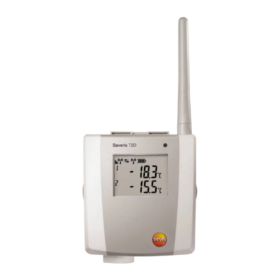
4 Product description Pos: 39 /TD/Produktbeschreibung/Übersicht/testo Saveris/01 Funkfühler/02 Funkfühler mit Display @ 0\mod_1189496687343_79.docx @ 4264 @ 35 @ 1 4.4.2. Radio probe with display Display for showing reading, battery and connection status as well as the field strength of the radio link. -
Page 31: Meaning Of The Led Displays At The Probes
( ) limit value. Number of the channel. Display for a second sensor in the probe. Pos: 40 /TD/Produktbeschreibung/Übersicht/testo Saveris/01 Funkfühler/03 Bedeutung der LED @ 0\mod_1190807440000_79.docx @ 5133 @ 355 @ 1 4.4.3. Meaning of the LED displays at the probes... -
Page 32: Saveris Ethernet Probes
Flashing 3 x red No connection to the Saveris base exists. Pos: 41 /TD/Produktbeschreibung/Übersicht/testo Saveris/02 Ethernet-Fühler/00 Ethernet-Fühler @ 1\mod_1197555728828_79.docx @ 6366 @ 2 @ 1 4.5. Saveris Ethernet probes Pos: 42 /TD/Produktbeschreibung/Übersicht/testo Saveris/02 Ethernet-Fühler/02 Ethernet-Fühler @ 1\mod_1197555730062_79.docx @ 6386 @ 5 @ 1 Display for showing the reading and transmission information. - Page 33 4 Product description Displays Quality of the connection. Battery status. Indicator as to whether a communication with the Saveris base is performed. Unit of the reading: • for humidity measurement • for current measurement • °Ctd °Ftd for dewpoint measurement.
-
Page 34: Saveris Router
4 Product description Pos: 43 /TD/Produktbeschreibung/Übersicht/testo Saveris/03 Router/01 Router @ 1\mod_1197555862937_79.docx @ 6406 @ 2 @ 1 4.6. Saveris router Antenna for the radio transmission of the measurement data LED for status display Connect button for connecting the router to the Saveris base... -
Page 35: Saveris Converter
4 Product description Pos: 44 /TD/Produktbeschreibung/Übersicht/testo Saveris/04 Converter/01 Converter @ 1\mod_1197557086312_79.docx @ 6416 @ 2 @ 1 4.7. Saveris converter Antenna for receiving the measurement data. LED for status display. Connect button for connecting the converter to the Saveris base and for a status request during operation. -
Page 36: Saveris Extender
4 Product description Pos: 45 /TD/Produktbeschreibung/Übersicht/testo Saveris/Extender Transport/Extender @ 7\mod_1291127467726_79.docx @ 74116 @ 2 @ 1 4.8. Saveris extender Antenna for receiving the measurement data. LED for status display. Connect key to query the status during operation. Catch for the wall mount. -
Page 37: Saveris Analog Coupler
Input for service interface. Input for power supply via mains unit. Pos: 47 /TD/Produktbeschreibung/Grundlegende Eigenschaften/testo Saveris PROF/01 Netzwerkumgebung @ 1\mod_1198065502375_79.docx @ 6744 @ 2 @ 1 4.10. Network environment The testo Saveris software is installed as a client-server installation. -
Page 38: First Steps
5 First steps Pos: 49 /TD/Überschriften/5. Erste Schritte @ 0\mod_1173774895039_79.docx @ 319 @ 1 @ 1 First steps Pos: 50 /TD/Erste Schritte/testo Saveris/00 Ablaufdiagramm Inbetriebnahme @ 0\mod_1189581707421_79.docx @ 4454 @ 2 @ 1 5.1. Flowchart Start Base with Inserting SIM card... - Page 39 5 First steps Installing software Integrating Ethernet Use Ethernet probe probes? Integrating converter converter? Start up hardware with the help of the startup wizard. Creating zones Performing the test run Configuring the alarms Mounting the hardware Starting software...
-
Page 40: Flow Chart (Saveris Mobile)
5 First steps Pos: 51 /TD/Erste Schritte/testo Saveris/00 Ablaufdiagramm Inbetriebnahme Transport @ 8\mod_1297414293206_79.docx @ 77043 @ 2 @ 1 5.2. Flow chart (Saveris mobile) Start Base with Insert SIM card GSM module? Connect USB cable and power supply to Connect USB cable... - Page 41 5 First steps Install software Integrate extender Connect Saveris base to PC and start up hardware Create zones Configure the alarms Start software Perform test run Mount the hardware...
-
Page 42: Inserting Sim Card (Optional)
5 First steps Pos: 52 /TD/Erste Schritte/testo Saveris/00 SIM-Karte einsetzen @ 1\mod_1197557316734_79.docx @ 6426 @ 2 @ 1 5.3. Inserting SIM card (optional) With a Saveris base with integrated GSM module, you must insert the SIM card. The SIM card for sending SMS messages is not included in the delivery and must be purchased separately from a mobile phone provider. -
Page 43: Connecting The Network Cable To The Saveris Base
5 First steps Pos: 53 /TD/Erste Schritte/testo Saveris/01 Netzwerkkabel an Base anschließen @ 1\mod_1197969679015_79.docx @ 6526 @ 2 @ 1 5.4. Connecting the network cable to the Saveris base 1. Loosen and remove screw connection. 2. Remove cover from Saveris Base. -
Page 44: Connecting Gsm Antenna (Optional)
Pos: 56 /TD/Erste Schritte/testo Saveris/01c Antenne anschließen @ 1\mod_1202123742093_79.docx @ 8056 @ @ 1 > Place antenna cable on the coaxial connection and screw Pos: 57 /TD/Erste Schritte/testo Saveris/02 Base mit Stromversorgung verbinden @ 0\mod_1188477940515_79.docx @ 2955 @ 2 @ 1... -
Page 45: Connecting Saveris Base With Power Supply
You can connect the Saveris base to the power supply via the included mains unit or via the 24 V AC/DC plug-in/screw terminal. Pos: 58 /TD/Erste Schritte/testo Saveris/02a-1 Stromversorgung über Netzteil verbinden @ 0\mod_1191328326843_79.docx @ 5392 @ 3 @ 1 5.6.1. -
Page 46: Power Supply Via Plug-In/Screw Connection (Optional)
5 First steps Pos: 61 /TD/Erste Schritte/testo Saveris/02b-1 Stromversorgung über AC/DC verbinden @ 0\mod_1191328406187_79.docx @ 5402 @ 3 @ 1 5.6.2. Power supply via plug-in/screw connection (optional) Pos: 62 /TD/Erste Schritte/testo Saveris/02b-2 PROF Stromversorgung über AC/DC verbinden @ 1\mod_1202124437660_79.docx @ 8078 @ @ 1 Pos: 63 /TD/Erste Schritte/testo Saveris/02b-3 Prof Stromversorgung über AC/DC verbinden @ 2\mod_1205493913317_79.docx @ 13002 @ @ 1... -
Page 47: Connecting Usb Cable (Optional)
Connecting USB cable (optional) For the commissioning, you can connect the Saveris base via a USB cable to the computer on which the Saveris client is installed. For this, first connect the USB cable to the Saveris base. During continuous operation, operate the base via the network cable, not via the USB cable. -
Page 48: Inserting Batteries In The Probes
5 First steps Pos: 65 /TD/Erste Schritte/testo Saveris/02 b Batterien am Fühler einlegen @ 0\mod_1191322124515_79.docx @ 5263 @ 2 @ 1 5.8. Inserting batteries in the probes 1. Loosen screws on the rear of the probe. 2. Remove housing cover of probe 3. -
Page 49: Connecting Radio Probe
5 First steps Pos: 66 /TD/Erste Schritte/testo Saveris/03 Fühler an der Base anmelden @ 0\mod_1188478029328_79.docx @ 2964 @ 2 @ 1 5.9. Connecting radio probe You can connect a maximum of 15 probes to the Saveris base directly via radio. - Page 50 5 First steps ✓ With Saveris H2D/H4D radio probes, the external humidity probe must be connected. 3. Hold down the connect key on the rear of the probe until the at the probe begins to flash orange. The LED at the probe briefly turns green if this was detected by the Saveris base.
-
Page 51: Installing Saveris Software
Saveris base; see Integrating a Saveris router (optional), page 58. Pos: 67 /TD/Erste Schritte/testo Saveris/05 PROF Saveris-Software installieren @ 2\mod_1205494611799_79.docx @ 13059 @ 2 @ 1 5.10. Installing Saveris software >... -
Page 52: Starting Up Hardware
> After completing the installation, restart the computer and log in with the same user name as before. Pos: 68 /TD/Erste Schritte/testo Saveris/04 Hardware inbetriebnehmen PRO @ 2\mod_1207049029259_79.docx @ 13961 @ 2 @ 1 5.11. Starting up hardware Use the installation instructions when starting up the system for the first time. - Page 53 5 First steps 2. Click on [Continue >]. The configuration data of the Saveris base are shown.
- Page 54 • Mark an existing project and click on [OK] to adopt the configuration data of the marked project for the new project. The system settings of the Saveris base that are based on the marked project are shown.
- Page 55 5 First steps 5. Click on [Units] to change the temperature unit for the system. 6. Click on [MKT] (mean kinetic temperature) to simulate the effect of temperature fluctuations over a certain period of time. > Mark the channel. > Click on [Add] to start the MKT calculation for the selected channel.
-
Page 56: Disconnecting Usb Cable
5 First steps 8. Make any further changes to the existing system settings as required (see installation instructions). Pos: 69 /TD/Erste Schritte/testo Saveris/02 PROF USB-Kabel entfernen @ 2\mod_1205494416530_79.docx @ 13040 @ 2 @ 1 5.12. Disconnecting USB cable 1. Disconnect the USB cable from the Saveris base. - Page 57 5 First steps The entry is available if Saveris Professional Client is installed • Saveris Viewer. The entry is available if Saveris Professional Viewer is installed Testo Saveris software program window is opened with Select project dialogue. If the software will not start, check whether the...
-
Page 58: Expand Measuring System
• With base V2, mixed operation with V1 components is only permissible for stationary use. Pos: 72 /TD/Erste Schritte/testo Saveris/Hardware erweitern/01 a Router einbinden/00 Router einsetzen @ 1\mod_1197549116203_79.docx @ 6304 @ 3 @ 1 5.14.1. Integrating a Saveris router (optional) You can use a Saveris router to optimize radio communication under poor structural conditions or to extend the radio path. -
Page 59: Connecting Router With Power Supply (Mains Unit)
5 First steps Pos: 73 /TD/Erste Schritte/testo Saveris/Hardware erweitern/01 a Router einbinden/01 Router-Strom @ 1\mod_1197548324640_79.docx @ 6294 @ 4 @ 1 5.14.1.1. Connecting router with power supply (mains unit) 1. Open cover 2. Insert mains cable 3. Insert mains plug into a socket. -
Page 60: Connecting Router With Power Supply (Ac/Dc)
5 First steps Pos: 74 /TD/Erste Schritte/testo Saveris/Hardware erweitern/01 a Router einbinden/01b Router-ACDC @ 1\mod_1197978273593_79.docx @ 6543 @ 4 @ 1 5.14.1.2. Connecting router with power supply (AC/DC) 1 Remove protection caps 2. Loosen screws on the rear of the router. - Page 61 5 First steps 5. Loosen clamping screws 6. Route cabling through the cable opening and insert in the terminals It is not necessary to note the polarity. 7. Tighten clamping screws.
- Page 62 The wall mounting of a router is performed in the same ways as for a probe; see "Mounting the probe on the wall". Pos: 75 /TD/Erste Schritte/testo Saveris/Hardware erweitern/01 a Router einbinden/02 Router anmelden @ 1\mod_1197548238578_79.docx @ 6274 @ 4 @ 1...
-
Page 63: Connecting Router
1. Change to the Info System menu at the Saveris base with the [▼] button. 2. Press [Enter] to call up the Login function. The status bar in the display shows that the Saveris base is ready for router detection. - Page 64 • Press [Enter] if further components are to be connected; see previous step. Pos: 76 /TD/Erste Schritte/testo Saveris/Hardware erweitern/01 a Router einbinden/03 Fühler zuweisen @ 1\mod_1197548250906_79.docx @ 6284 @ 4 @ 1...
-
Page 65: Assigning Probes
5 First steps 5.14.1.4. Assigning probes To assign a probe to a router, both must be connected in the Saveris base. 1. Under Start All Programs Testo click on Saveris Startup Wizard. The welcome dialogue of the startup assistant is shown. - Page 66 > Perform steps 4 to 5 for all remaining probes whose measurement data is to be transmitted to the Saveris base via a router. 6. Position the probes and router at their mounting locations to check the radio links.
-
Page 67: Connecting Routers In Series
If you want to use probes in a router cascade, see Connecting routers in series, page 67 see Connecting routers in series, page 67 Pos: 77 /TD/Erste Schritte/testo Saveris/Hardware erweitern/01 a Router einbinden/04 Router hinteinanderschalten @ 8\mod_1295275223441_79.docx @ 75773 @ 4 @ 1 5.14.1.5. Connecting routers in series Max. - Page 68 5 First steps 2. Click on [Next >]. System status dialogue box is displayed with the tab General.
- Page 69 5 First steps 3. Switch to the Router tab. 4. Click on [Cascade routers]. Cascade routers window is opened. 5. Select routers in the order in which they should be connected in series starting at the base (from left to right).
- Page 70 8. Place the routers in their installation locations to check the radio connections. 9. Briefly press Connect on the back of the router that is next in the series after the Saveris base (router 1 in the diagram). If the LED on the front of the router flashes •...
-
Page 71: Assigning An Ip Address To The Saveris Base (Optional)
5 First steps Pos: 78 /TD/Erste Schritte/testo Saveris/Hardware erweitern/01 b IP-Adresse der Base zuweisen @ 12\mod_1338376877611_79.docx @ 125816 @ 3 @ 1 5.14.2. Assigning an IP address to the Saveris base (optional) If an Ethernet probe, converter and/or extender is integrated into the Saveris system, a static IP address should first be assigned for the Saveris base. -
Page 72: Integrating Saveris Converter (Optional)
5. Follow the wizard's instructions and assign the IP address for the Saveris base. see Installing Saveris software, page 51 Pos: 79 /TD/Erste Schritte/testo Saveris/Hardware erweitern/02 Converter einbinden/00 Converter einsetzen @ 1\mod_1197550607093_79.docx @ 6315 @ 35 @ 1 5.14.3. Integrating Saveris converter (optional) -
Page 73: Integrating Saveris Ethernet Probe (Optional)
The probe/router is connected at the converter and this transmits the measurement data to the Saveris base. Pos: 80 /TD/Erste Schritte/testo Saveris/Hardware erweitern/03 Ethernet-Fühler einbinden/00 Ethernet-Fühler einsetzen @ 1\mod_1197552336953_79.docx @ 6336 @ 3 @ 1 5.14.4. Integrating Saveris Ethernet probe (optional) In addition to the Saveris radio probes, you can use probes that are connected to the Ethernet interface of the Saveris base. -
Page 74: Connecting The Network Cable
5 First steps 5.14.4.1. Connecting the network cable. Only use high-quality network cables with a diameter between 5.8 mm and 6.8 mm to ensure the leaktightness of the probe housing. Only use cables with an intact clip end. 1. Loosen screws on the rear of the probe and remove the housing cover... -
Page 75: Connecting Ethernet Probe With Power Supply (Mains Unit)
You can connect the probe to the network via a network hub or directly at the Saveris base via the Ethernet jack. Pos: 82 /TD/Erste Schritte/testo Saveris/Hardware erweitern/03 Ethernet-Fühler einbinden/01c Stromversorgung @ 1\mod_1203423817781_79.docx @ 8270 @ 4 @ 1 5.14.4.2. -
Page 76: Connecting Usb Cable And Installing Driver (Optional)
2. Insert mains cable 3. Insert mains plug into a socket. Pos: 83 /TD/Erste Schritte/testo Saveris/Hardware erweitern/03 Ethernet-Fühler einbinden/01b USB-Kabel @ 1\mod_1203423817203_79.docx @ 8259 @ 4 @ 1 5.14.4.3. Connecting USB cable and installing driver (optional) 1. -
Page 77: Assigning An Ip Address To The Saveris Base (Optional)
5 First steps Pos: 84 /TD/Erste Schritte/testo Saveris/Hardware erweitern/01 b IP-Adresse der Base zuweisen @ 12\mod_1338376877611_79.docx @ 125816 @ 3 @ 1 5.14.5. Assigning an IP address to the Saveris base (optional) If an Ethernet probe, converter and/or extender is integrated into the Saveris system, a static IP address should first be assigned for the Saveris base. -
Page 78: Assigning Connection Data
5. Follow the wizard's instructions and assign the IP address for the Saveris base. see Installing Saveris software, page 51 Pos: 85 /TD/Erste Schritte/testo Saveris/Hardware erweitern/03 Ethernet-Fühler einbinden/03 Verbindungsdaten zuweisen @ 1\mod_1203421515781_79.docx @ 8226 @ 4 @ 1 5.14.5.1. Assigning connection data You must now enter the connection settings for the Ethernet probes. - Page 79 The dialogue for the entry of the connection data for the base is shown. 5. Enter IP address or DNS entry of the Saveris base. The IP address can be read off at the Saveris base in Info Base menu; see Displays, page 17.
-
Page 80: Connecting Ethernet Probe With The Saveris Base
Ethernet probes in the display of the base is increased by 1; see Displays, page 17. Pos: 86 /TD/Erste Schritte/testo Saveris/Hardware erweitern/03 Ethernet-Fühler einbinden/Ethernet-Fühler mit der Saveris Base verbinden @ 2\mod_1207050082922_79.docx @ 13997 @ 4 @ 1 5.14.5.2. - Page 81 5 First steps Commission new probe dialogue box is displayed. 3. Leave default setting and click on [Next >]. The list of probes newly registered in the Saveris base is displayed.
- Page 82 5 First steps 4. Click on [Add stationary zone]. 5. Open the selection list via button and select the zone to which the probe should be assigned. 6. Click on [Next >].
- Page 83 5 First steps 7. Click in the TE type field and enter the thermocouple element type (K, J, or S) if this information is necessary for the device. 8. If required, change the default values in fields Probe name Channel name.
- Page 84 5 First steps 11. Enter Measuring cycle and define its Unit. The measuring cycle determines the intervals at which a new measured value is saved in the Saveris base. Possible settings for the unit: • (second) • (minute) • (hour).
-
Page 85: Integrating A Saveris Extender
15. Confirm the message by clicking [OK]. The new hardware is now ready to be used. Pos: 88 /TD/Erste Schritte/testo Saveris/Hardware erweitern/Extender einbinden Transport/Extender einsetzen Transport @ 8\mod_1291277100991_79.docx @ 74295 @ 3 @ 1 5.14.6. Integrating a Saveris extender... - Page 86 You can connect several Saveris extenders to the Saveris base via a switch. Bearing this in mind, note that up to 20 Saveris extenders can be registered on the Saveris base with a maximum number of 150 probes or 450 measurement channels.
-
Page 87: Integrating A Saveris Cockpit Unit (Optional)
5 First steps Pos: 89 /TD/Erste Schritte/testo Saveris/Hardware erweitern/Cockpit Unit einbinden Transport/Cockpit Unit einsetzen Transport @ 8\mod_1291277188052_79.docx @ 74328 @ 3 @ 1 5.14.7. Integrating a Saveris cockpit unit (optional) The Saveris cockpit unit is used to start and stop tours manually and display the measured values of the assigned radio probes during transportation. -
Page 88: Registering A Saveris Cockpit Unit
Saveris base is ready to detect the Saveris cockpit unit. The Saveris cockpit unit can be connected briefly to the PC via the USB port for a power supply while logging into the Saveris base. The driver search, which opens automatically on the PC, can be closed. -
Page 89: Fitting A Saveris Cockpit Unit In The Driver's Cab And Connecting To A Power Supply
Pos: 91 /TD/Erste Schritte/testo Saveris/Hardware erweitern/Cockpit Unit einbinden Transport/Cockpit Unit Befestigung Stromversorgung Transport @ 8\mod_1291277189568_79.docx @ 74361 @ 4 @ 1 5.14.7.2. Fitting a Saveris cockpit unit in the driver's cab and connecting to a power supply Do not fit the Saveris cockpit unit while driving. - Page 90 4. Connect adapter (article no. 0554 1038) with the USB cable and plug into the vehicle socket. Green LED lights up when the Saveris cockpit unit is supplied with power. Saveris cockpit unit is ready for use. Before each trip, particularly when temperatures fluctuate,...
-
Page 91: Integrating Saveris Analog Coupler (Optional)
5 First steps Pos: 92 /TD/Erste Schritte/testo Saveris/Hardware erweitern/04 Analogkoppler einbinden/00 Analogkoppler einsetzen @ 4\mod_1248880773887_79.docx @ 46514 @ 3555 @ 1 5.14.8. Integrating Saveris analog coupler (optional) Using a Saveris analog coupler, you can integrate a transmitter with standardized current/voltage interfaces into the Saveris measuring system and monitor it. - Page 92 5 First steps 2. Click on [Next >]. Commission new probe dialogue is shown.
- Page 93 5 First steps 3. Leave default setting and click on [Next >]. Analog couplers can always only be additionally included in the configuration and cannot be used as a replacement for ones that are already present. Scale dialogue is displayed.
- Page 94 7. Select number of Decimal places. 8. Click on [Set up sum channel] if the summation of a particular unit is required. 9. Click on [Next >]. The list of the probes newly registered in the Saveris base is shown.
- Page 95 5 First steps 10. Click on [New stationary zone]. 11. Open the selection list via button and select the zone to which the probe should be assigned. 12. Click on [Next >]. 13. Click in the TE type field and enter the thermocouple element type (K, J, or S) if this information is necessary for the device.
- Page 96 • (minute) • (hour). 18. Click on [Next > If a router is registered on the Saveris base, the configuration of the connection type for the probes is shown. If you have not registered a router, continue with step 24.
- Page 97 Probes in a mobile zone cannot be assigned to a router. 21. Perform steps 21 and 22 for any other probes with measurement data to be transmitted to the Saveris base via a router. 22. Click on [Next >].
-
Page 98: Performing The Test Run
25. Confirm the message by clicking [OK]. The new hardware is now ready to be used. Pos: 93 /TD/Erste Schritte/testo Saveris/06 ****Probelauf/00 Probelauf und Abnahme durchführen @ 0\mod_1189157354187_79.docx @ 4054 @ 2 @ 1 5.15. Performing the test run The test run must be performed to ensure proper operation of the measuring system. -
Page 99: Testing The System
The LED at the probe shows the connection status; also see "Meaning of the LED displays at the probes ". Pos: 95 /TD/Erste Schritte/testo Saveris/06 ****Probelauf/Systemtest durchführen @ 10\mod_1321361553028_79.docx @ 103136 @ 3 @ 1 5.15.2. Testing the system For a simple system test: •... - Page 100 After a successful system test, a base backup is recommended, see Saving data in the Saveris base, page 183. Pos: 99 /TD/Erste Schritte/testo Saveris/07 **** Montage der Hardware/00 Hardware montieren @ 0\mod_1189157579984_79.docx @ 4124 @ 3 @ 1 Only during mobile monitoring...
-
Page 101: Mounting The Hardware
After mounting, perform another test run of the system; also see "Performing the test run". Pos: 100 /TD/Erste Schritte/testo Saveris/07 **** Montage der Hardware/01 Base an der Wand montieren @ 0\mod_1189157492531_79.docx @ 4105 @ 3 @ 1 5.16.1. Mounting the Saveris base on the wall... - Page 102 (e.g. drill hole, insert anchor plug). 4. Fasten wall bracket using appropriate screws. 5. Place Saveris base on the wall bracket and secure with screw Pos: 101 /TD/Erste Schritte/testo Saveris/07 **** Montage der Hardware/01b Base mit Standfuß @ 0\mod_1190975629546_79.docx @ 5233 @ 3 @ 1...
-
Page 103: Setting Up Saveris Base With Stand
The Saveris base must be positioned close enough to the computer used and a possible power supply in accordance with the cabling provided. 1. Place the Saveris base on the stand 2. Set up the Saveris base at the desired location. -
Page 104: Mounting The Probe On The Wall
5 First steps Pos: 102 /TD/Erste Schritte/testo Saveris/07 **** Montage der Hardware/03 Fühler montieren @ 0\mod_1189157541812_79.docx @ 4114 @ 3 @ 1 5.16.3. Mounting the probe on the wall When selecting the location, take into account the following points: •... - Page 105 Please refer to "Removing probe from wall bracket" for removing the probe from the wall bracket. Pos: 103 /TD/Erste Schritte/testo Saveris/Hinweis Schutzgehäuse @ 8\mod_1297344248560_79.docx @ 77003 @ @ 1 The radio probes T1/T1D/T2/T2D can be protected with the Saveris protective housing (article no. 0572 0200) against impact or prepared for high-pressure cleaning.
-
Page 106: Checking The Measuring System Again
5 First steps Pos: 104 /TD/Erste Schritte/testo Saveris/07 **** Montage der Hardware/04 System prüfen @ 0\mod_1191327191562_79.docx @ 5362 @ 3 @ 1 5.16.4. Checking the measuring system again > Perform another test run at the measuring system; see "Performing the test run". -
Page 107: Using The Product
6 Using the product Pos: 106 /TD/Überschriften/6. Produkt verwenden @ 0\mod_1173774928554_79.docx @ 328 @ 2 @ 1 Using the product Pos: 107 /TD/Produkt verwenden/testo Saveris/01 Start/02_Bedienoberfläche_01 @ 0\mod_1189076833359_79.docx @ 3943 @ 2 @ 1 6.1. User interface In this chapter, you learn how the user interface of the Saveris software is designed. - Page 108 Select project Selection of all projects already created. Pos: 110 /TD/Produkt verwenden/testo Saveris/01 Start/02_Bedienoberfläche_04 @ 1\mod_1197983805828_79.docx @ 6613 @ @ 1 Data range The measurement data are managed in the data range. You can create new groups of readings and copy the data from individual channels within the groups.
-
Page 109: Menus And Commands
6 Using the product Pos: 116 /TD/Produkt verwenden/testo Saveris/02 Menüs und Befehle der Ribbon-Leiste/00 Menüs und Befehle @ 0\mod_1190279903078_79.docx @ 4975 @ 3 @ 1 6.2. Menus and commands In this chapter, you learn which menus and commands are available to you and what you can use these commands for. - Page 110 Shows the calendar for the selection of the month in order to call up the data from the corresponding month from the database. Pos: 124 /TD/Produkt verwenden/testo Saveris/02 Menüs und Befehle der Ribbon-Leiste/01 Start/PRO/04-2 PRO Ansicht @ 0\mod_1189607578640_79.docx @ 4657 @ 5 @ 1 Start View...
- Page 111 Opens a search window in the Data System navigation areas in which zones and channels can be searched through via textual word search. Pos: 128 /TD/Produkt verwenden/testo Saveris/02 Menüs und Befehle der Ribbon-Leiste/02 Bearbeiten/00 Menü Bearbeiten @ 0\mod_1190280106796_79.docx @ 4993 @ 5 @ 1...
-
Page 112: Edit
6 Using the product 6.2.2. Edit Pos: 129 /TD/Produkt verwenden/testo Saveris/02 Menüs und Befehle der Ribbon-Leiste/02 Bearbeiten/PRO/02 Bearbeiten (Diagramm)_Pro @ 0\mod_1193998566609_79.docx @ 5673 @ 5 @ 1 Editing in the diagram view Edit menu (diagram) is only displayed if the diagram has been activated by clicking into the window. - Page 113 Pos: 130 /TD/Produkt verwenden/testo Saveris/02 Menüs und Befehle der Ribbon-Leiste/02 Bearbeiten/PRO/03 Bearbeiten (Tabelle)_PRO @ 15\mod_1381823336522_79.docx @ 178185 @ 55 @ 1 Edit in the table view Edit (table) menu is only shown if the table is activated by clicking in the window.
- Page 114 Maximum Shows the largest reading of the selected channel within the table. Pos: 131 /TD/Produkt verwenden/testo Saveris/02 Menüs und Befehle der Ribbon-Leiste/02 Bearbeiten/PRO/04 Bearbeiten (Zahlenfeld) @ 0\mod_1189673582453_79.docx @ 4755 @ 5 @ 1 Editing in the monitor view Edit (monitor) menu is only shown if the diagram window is activated by clicking in the window.
-
Page 115: Axes
You can move the fields with the left mouse button and change their size. Pos: 132 /TD/Produkt verwenden/testo Saveris/02 Menüs und Befehle der Ribbon-Leiste/04 Menü Achsen @ 14\mod_1372857955826_79.docx @ 170193 @ 5 @ 1 6.2.3. Axes Pos: 133 /TD/Produkt verwenden/testo Saveris/02 Menüs und Befehle der Ribbon-Leiste/04 Achsen @ 14\mod_1372856833485_79.docx @ 170019 @ 555 @ 1... -
Page 116: Template
The software version number can be found among the service data. Pos: 138 /TD/Produkt verwenden/testo Saveris/02 Menüs und Befehle der Ribbon-Leiste/06 Menü Projekt auswählen @ 3\mod_1233571007869_79.docx @ 23692 @ 3 @ 1 6.2.6. Selecting projects The project data for all projects already created can be displayed using the selection menu without having to restart the software. -
Page 117: Creating, Editing And Deleting Zones
Pos: 141 /TD/Produkt verwenden/testo Saveris/Kühlcontainer einrichten - Transport/Mobile Zone anlegen Erklärung @ 8\mod_1291308189666_79.docx @ 74528 @ @ 1 The assignment of radio probes to zones is carried out in the startup wizard. -
Page 118: Changing Zones
6 Using the product Pos: 143 /TD/Produkt verwenden/testo Saveris/03 Gruppen einrichten/organisieren/06 Zonen ändern Transport @ 8\mod_1299139946694_79.docx @ 77316 @ 3 @ 1 6.3.2. Changing zones You can add channels to an existing zone. You can delete channels that you no longer require in a zone from this zone. You can also change the name of the zone. -
Page 119: Setting Up Tours
In the Permissions window, the selected users are assigned to the relevant zone. 7. Click on OK. Pos: 146 /TD/Produkt verwenden/testo Saveris/Tour planen - Transport/Tour planen @ 8\mod_1291303318802_79.docx @ 74494 @ 3353333 @ 1 6.4. Setting up tours 6.4.1. Tour description 1. -
Page 120: Planning Tours
This description only relates to tours that are planned for the future. For this, a tour is created via the software. This is recommended if no Saveris cockpit unit is used for tour entry. 1. In the navigation area, click on Tour administration. -
Page 121: Defining Tours
6 Using the product 3. Enter the name of the new tour. The name appears in the tour calendar and in the Saveris cockpit unit. 4. Select mobile zones. > If required: Add tour description. 5. Select period during which the tour should be carried out. -
Page 122: Displaying Tours
1 Selection of the displayed mobile zone 2 Adjustable filter options 3 Calendar view 4 Overview of the tours carried out and the status of the data transfer to the Saveris base: • green: Data transferred complete • yellow: Data transfer in progress •... -
Page 123: Searching For Tours
6 Using the product 6.4.5. Searching for tours 1. In the navigation area, click on Tour administration. 2. Select Tour finder. 3. Select or enter required search options. When searching for tours within a time frame, the tour is considered as a whole. No result is shown if only one part of the tour is within the time frame searched. -
Page 124: Configuring The Alarms
The Saveris base therefore only outputs system alarms for probes in mobile zones – limit value breaches are suppressed. Pos: 149 /TD/Produkt verwenden/testo Saveris/04 Alarme konfigurieren/PRO/01 Alarm vorkonfigurieren - 00 Alarme der Base einrichten @ 12\mod_1338379733044_79.docx @ 125883 @ 344 @ 1... -
Page 125: Setting Up Base Alarms
6 Using the product 6.5.1. Setting up base alarms Any configuration changes are only transferred to the probe/base once you have exited the Alarm management menu! You should therefore exit the Alarm management menu after editing. 6.5.1.1. Setting up alarms 1. - Page 126 6 Using the product Display Explanation Device alarm Setting options for the base alarms Saveris Base Missing PC connection: no response from the PC Memory almost full: alarm when the base memory overflows. No GSM network: alarm when there is no GSM connection.
-
Page 127: Configuring Scheduling
6 Using the product 6.5.1.2. Configuring scheduling All alarms across the entire system are paused/activated via scheduling. 1. Click on Activate scheduling. Alarms scheduling button is activated. 2. Click on Alarms scheduling. An input window with a complete scheduling system is displayed. -
Page 128: Setting Up Alarm Groups
The input window is closed, the modifications to the scheduling are accepted. Pos: 150 /TD/Produkt verwenden/testo Saveris/04 Alarme konfigurieren/PRO/01 Alarm vorkonfigurieren - 01 Gruppen PRO @ 0\mod_1189684344906_79.docx @ 4843 @ 3353535555455 @ 1 6.5.2. Setting up alarm groups 6.5.2.1. - Page 129 LoBat and power failure Alarm conditions: trigger acknowledged alarms after [min] Alarm output Saveris Base: settings for relays, audible signal and light signal. [Apply entries] Saves the alarm settings of an alarm group.
-
Page 130: Channels
6 Using the product Remove from group 1. Right-click on component, then click on [Remove from group]. The component is removed from the assigned alarm group. Delete group 1. Right-click on component, then click on [Delete this group]. The assigned alarm group is deleted, all components that were assigned to this group are now without an alarm group. - Page 131 Alarm conditions: settings for lower limit delay [Measurements], upper limit delay [Measurements] and trigger acknowledged alarms after [min] Alarm output Saveris Base: settings for relays, audible signal and light signal. [Apply entries] Saves the alarm settings of an alarm group.
-
Page 132: Creating Recipient
The alarm group assigned to this component is applied to all other components. Pos: 151 /TD/Produkt verwenden/testo Saveris/04 Alarme konfigurieren/PRO/01 Alarm vorkonfigurieren - 02 Empfänger @ 0\mod_1189684391828_79.docx @ 4853 @ 25553 @ 1 6.5.3. Creating recipient Any configuration changes are only transferred to the... - Page 133 6 Using the product The recipient data are shown in the display range. Designation Description [New receiver] Creates a new entry in the receiver list. Receiver list List of possible recipients. The telephone number in the receiver list comes from the commissioning.
- Page 134 6 Using the product Designation Description Time entries are automatically rounded up/down to 1/4 hour. To change the availability time, you must delete the existing entry using the right mouse button and enter a new availability time. Creating new recipient 1.
-
Page 135: Creating Alarm Rules
6 Using the product Pos: 152 /TD/Produkt verwenden/testo Saveris/04 Alarme konfigurieren/PRO/01 Alarm vorkonfigurieren - 03 Regeln @ 0\mod_1189684413734_79.docx @ 4863 @ 25 @ 1 6.5.4. Creating alarm rules Any configuration changes are only transferred to the probe/base once you have exited the... - Page 136 6 Using the product Designation Description Forward to Time interval after which the alarm message should be sent to another recipient if the first recipient does not acknowledge the alarm. to 2nd receiver Recipient who is to receive the forwarded alarm message if the first recipient does not acknowledge the alarm.
- Page 137 6 Using the product 4. Determine the first receiver who is to receive the alarm message in the selection list of the same name. 5. Click on [Continue >]. The dialogue for the forwarding function or for finishing the alarm rule is shown. 6.
- Page 138 The wizard is closed and the new rule is added to the list of alarm messages. 14. Exit "Alarm Management" menu. Alarm settings are transferred to the devices. Pos: 153 /TD/Produkt verwenden/testo Saveris/04 Alarme konfigurieren/PRO/03 Alarmübersicht @ 1\mod_1198162959421_79.docx @ 6863 @ 3 @ 1...
-
Page 139: Alarm Overview
2. Click on Alarm rules. The defined alarms are displayed in the display area. Pos: 154 /TD/Produkt verwenden/testo Saveris/04 Alarme konfigurieren/PRO/04 Quittierungskommentar @ 10\mod_1320920797023_79.docx @ 96546 @ 3 @ 1 6.5.6. Comments for acknowledging alarms You can create standardised acknowledgement comments, which are displayed in the acknowledgement window as a selection list. -
Page 140: Analyzing Series Of Measurements
• Table function if the data should be displayed as a table. Pos: 156 /TD/Produkt verwenden/testo Saveris/05a Diagramme analysieren/00 Diagramme @ 0\mod_1188996581406_79.docx @ 3484 @ 3 @ 1 6.6.1. Diagram view In this view, the readings are shown as line diagrams. -
Page 141: Enlarging The View
6 Using the product Pos: 157 /TD/Produkt verwenden/testo Saveris/05a Diagramme analysieren/01 Vergrößern @ 0\mod_1188996582156_79.docx @ 3494 @ 3 @ 1 6.6.1.1. Enlarging the view Zoom in on a detail of the diagram to check the behavior of the readings within a specific time span, for example. -
Page 142: Text Field
6 Using the product Pos: 160 /TD/Produkt verwenden/testo Saveris/05a-2 Kurveneigenschaften/00 Kurveneigenschaften @ 0\mod_1188996704171_79.docx @ 3636 @ 45 @ 1 6.6.1.4. Text field Insert a text field to enter comments and additional information in the curve. Insert text field The text field may potentially cover parts of the curve. In this event, the text field must be positioned in such a way to ensure that the curve is not concealed. - Page 143 6 Using the product Pos: 161 /TD/Produkt verwenden/testo Saveris/05a-2 Kurveneigenschaften/01 Register Kurve bearbeiten @ 0\mod_1188996705609_79.docx @ 3666 @ 5 @ 1 Curve Designation Explanation Smooth The measurement points are connected by an interpolated curve; the plot-points on the curve between two measurement points are estimated mathematically.
- Page 144 "1" degree of regression the linear trend, a higher value helps in the event of curves with several extreme values. Pos: 162 /TD/Produkt verwenden/testo Saveris/05a-2 Kurveneigenschaften/02 Register Grenzwertanzeige @ 0\mod_1188996705265_79.docx @ 3656 @ 5 @ 1 Range limits Designation Explanation...
- Page 145 Undershoot Colour selection for the fill of the area below the lower limit value. Pos: 163 /TD/Produkt verwenden/testo Saveris/05a-2 Kurveneigenschaften/04 Register Stat. Berechnung @ 0\mod_1188996705906_79.docx @ 3676 @ 4 @ 1 Statistical computation Designation Explanation Min.
-
Page 146: Settings For The Axes In The Diagram
Recalculate Recalculates the curve. Pos: 164 /TD/Produkt verwenden/testo Saveris/05a-3 Achseinstellungen/05 Einstellungen für die Achsen im Diagramm @ 0\mod_1193999542168_79.docx @ 5684 @ 4 @ 1 6.6.1.6. Settings for the axes in the diagram Change the settings of the axes in the diagram to adapt the representation to your requirements. - Page 147 Manual entry of the grid. division is activated) Pos: 166 /TD/Produkt verwenden/testo Saveris/05a-3 Achseinstellungen/07 Zeitachse @ 0\mod_1193999544199_79.docx @ 5704 @ 5 @ 1 Settings for the time axis > With the right mouse button, click on the time axis in the diagram.
- Page 148 6 Using the product Designation Explanation [OK] Applies the settings until other data are called up. The dialogue is closed. [Cancel] Closes the dialogue without applying any changes. Position Shows a freely-definable extract of the diagram. Autom. scaling... Shows the entire diagram in the window. Extract Shows a fixed, defined extract that can be moved over the time axis.
-
Page 149: Histogram View
• (hour) • (day). Pos: 167 /TD/Produkt verwenden/testo Saveris/05 a-3 Histogramm/00 Histogramm @ 1\mod_1198143235359_79.docx @ 6804 @ 3 @ 1 6.6.2. Histogram view In this view, the readings are shown as a histogram, meaning the last reading of a channel is shown as a column. -
Page 150: Marking Readings
The table view of the selected data is shown. > If necessary, deactivate channels via the checkboxes for the display. Pos: 170 /TD/Produkt verwenden/testo Saveris/05b Tabellen analysieren/01 Messwerte markieren @ 0\mod_1188996635625_79.docx @ 3565 @ 4 @ 1 6.6.4.1. Marking readings Mark specific readings to perform a statistical computation for part of the measurement series, for example. -
Page 151: Dropping The Marking
Drop marking. The marking of the readings is deleted. Pos: 172 /TD/Produkt verwenden/testo Saveris/05b Tabellen analysieren/03 Extremwert oder Mittelwert einfügen @ 0\mod_1188996637890_79.docx @ 3585 @ 4 @ 1 6.6.4.3. Inserting extreme values or mean in the table Insert the minimum/maximum reading as well as the mean from the whole table at the end of the table. -
Page 152: Dropping Compression
• (day). 3. Click on [OK]. The dialogue is closed and the table is shown compressed. Pos: 174 /TD/Produkt verwenden/testo Saveris/05b Tabellen analysieren/05 Verdichtung aufheben @ 0\mod_1188996639140_79.docx @ 3605 @ 4 @ 1 6.6.4.5. Dropping compression > Click on Edit... -
Page 153: Analyzing Alarms
Comments on an alarm in the column of the same name. Pos: 179 /TD/Produkt verwenden/testo Saveris/06c Alarme analysieren/02 Prof Alarm quittieren @ 2\mod_1207047182185_79.docx @ 13943 @ 3 @ 1 6.7.2. Acknowledging an alarm If you acknowledge an alarm at the Saveris base, this is carried over into the software. - Page 154 The Saveris base has triggered a system alarm. The Saveris base has triggered a warning. A limit value has been breached and the Saveris base has triggered an alarm. Time Date and time when the alarm was triggered. 4. Click on the symbol in front of the alarm entry you want to confirm.
-
Page 155: Creating Evaluations
Saveris base, the alarm relay and alarm status stop flashing and the alarm is deleted. Pos: 180 /TD/Produkt verwenden/testo Saveris/07 Berichte/00 Berichte erstellen PROF @ 4\mod_1246526201868_79.docx @ 45623 @ 2 @ 1 6.8. -
Page 156: Archiving With Automatic Reports
The reports are saved as PDF files so that they can easily be read or sent per e-mail but without being able to change the data stock. Pos: 183 /TD/Produkt verwenden/testo Saveris/07 Berichte/03 ** Langzeitarchivierung und Datensicherung @ 0\mod_1190970854000_79.docx @ 5223 @ 3 @ 1 6.9. - Page 157 To start a new project, you must register all components on the Saveris base again and then restart the hardware.
-
Page 158: System Settings
6 Using the product Pos: 184 /TD/Produkt verwenden/testo Saveris/09 Einstellungen System/00a Einstellungen System Transport @ 8\mod_1295540616674_79.docx @ 75913 @ 255 @ 1 6.10. System settings In this menu, determine the settings for the Saveris base, the radio probes and – if installed in the measuring system – the Ethernet probes, router, converter, analogue coupler, extender and cockpit units. - Page 159 Assigning zones, page 118. Audit trail Display, save or export audit trail file. Hash code Generates a hash code Raw data Creates a vi2 file per probe with all export measurement data from the Saveris base (not from the database).
-
Page 160: General Settings For The Saveris Base
Cockpit unit with the settings for the cockpit units registered on the Saveris base. Pos: 185 /TD/Produkt verwenden/testo Saveris/09 Einstellungen System/01 Allgemein @ 0\mod_1188997905046_79.docx @ 3801 @ 3 @ 1 6.10.1. General settings for the Saveris base Via this menu item, you can for example synchronize the date and time of the Saveris base with the values of the computer. -
Page 161: Show Operating Data Of The Probes
Saveris base. Date and time Date and time of the Saveris base. Pos: 186 /TD/Produkt verwenden/testo Saveris/09 Einstellungen System/03 Betriebsdaten @ 1\mod_1197536994375_79.docx @ 6253 @ 3 @ 1 6.10.2. Show operating data of the probes. Using this menu item, you can check when the last data were received from a probe, for example, and the duration until the next readings can be expected. -
Page 162: Settings For The Radio Probe
6 Using the product Pos: 187 /TD/Produkt verwenden/testo Saveris/09 Einstellungen System/03 Wireless probes @ 0\mod_1189598701171_79.docx @ 4463 @ 2 @ 1 6.10.3. Settings for the radio probe Using this menu item you can, for example, check the battery status of the probe or the quality of the radio transmission. - Page 163 Briefly press the connect key on the corresponding humidity probe. Firmware Version number of the probe's instrument software. Radio quality Field strength of the last radio link to the Saveris base. Communication successfully transferred data in total or statistics current...
- Page 164 Saveris base/extender. Pos: 189 /TD/Produkt verwenden/testo Saveris/09 Einstellungen System/04 Ethernet probes @ 0\mod_1190896768531_79.docx @ 5172 @ 3 @ 1...
-
Page 165: Ethernet Probes
6 Using the product 6.10.4. Ethernet probes Using this menu item, you can check the version of the instrument software of an Ethernet probe, for example. 1. Open the Ethernet probe entry. 2. Click on one of the probe names to open the information on the probe. -
Page 166: Analog Coupler
Pos: 190 /TD/Produkt verwenden/testo Saveris/09 Einstellungen System/07 Analogkoppler @ 4\mod_1248704611882_79.docx @ 46423 @ 3 @ 1 6.10.5. Analog coupler Via this menu item you can change the power supply of the analog coupler or reset a sum channel, for example. -
Page 167: Saveris Cockpit Unit
Button for resetting the sum channel. The channel] sum channel is reset to 0.00. Pos: 191 /TD/Produkt verwenden/testo Saveris/09 Einstellungen System/08 Cockpit Units @ 8\mod_1295540867044_79.docx @ 75946 @ 3 @ 1 6.10.6. Saveris cockpit unit Via this menu option, you can configure the measured value printout using the Testo standard printer. - Page 168 Identify alarms Identification of the alarms on the measured value printout with (*) Print signature line Additional signature line, e.g. for the goods recipient Pos: 192 /TD/Produkt verwenden/testo Saveris/10 Einstellungen Berichte/00 Einstellungen Berichte @ 0\mod_1189494078218_79.docx @ 4243 @ 3 @ 1...
-
Page 169: Report Settings
In the data window, the Settings for automatic reports sub- menu is displayed. Pos: 193 /TD/Produkt verwenden/testo Saveris/10 Einstellungen Berichte/01 Settings @ 0\mod_1188997925140_79.docx @ 3821 @ @ 1 Designation Explanation [New report] Adds a new reporting task to the list. - Page 170 6 Using the product Designation Explanation Group box Content When option is enabled, the corresponding data sheet is attached to the report • Detailed • Compact • Brief • Custom • Insert logo • Insert signature line Timing of the report Specify whether the report is to be generation generated daily,...
- Page 171 Creates a report, thus testing the configured report functions. Apply settings Saves the report configurations. The storage location for the reports was determined during the installation of the Saveris software. The path specification is shown below the Determine folder field.
-
Page 172: Maintaining The Product
Testing the system, page 99. Pos: 197 /TD/Produkt instand halten/testo Saveris/00 Ersatz von Komponenten @ 0\mod_1188476464890_79.docx @ 2909 @ 2 @ 1 7.2. Replacement of components You can shut down a component – probe, converter or router – at any time because this is temporarily not in use or to replace it with a new component, for example, in the event of a defect. -
Page 173: Deleting Components
7 Maintaining the product 7.2.1. Deleting components 1. Under Start All Programs Testo click on Testo Saveris Startup Wizard. The welcome dialogue of the startup wizard is shown. 2. Click on [Continue >]. System status dialogue with the General tab is shown. - Page 174 7 Maintaining the product 3. Change to Projects tab. 4. Click on [De-register component]. De-register component dialogue is shown. 5. Activate the checkbox in front of the component that is to be de- registered from the system. Before deleting a router, you should assign the relevant assigned probes directly to the base to ensure data availability.
-
Page 175: Adding New Components
7 Maintaining the product Pos: 199 /TD/Produkt instand halten/testo Saveris/02 Komponenten hinzufügen Transport @ 0\mod_1188476503984_79.docx @ 2918 @ 3 @ 1 7.2.2. Adding new components With the subsequent addition of a component, it is possible that the measuring cycle is not synchronous with that of the components already present. - Page 176 4. Leave default setting and click on [Next >]. The list of probes newly registered in the Saveris base is displayed. 5. To distribute the probes already registered on the system between stationary or mobile zones depending on the purpose...
- Page 177 The settings for the measuring cycle are displayed. 12. Enter Measuring cycle and define its Unit. The measuring cycle determines the intervals at which a new measured value is saved in the Saveris base. Possible settings for the unit: • (second) •...
- Page 178 13. Click on [Next >]. If a router is registered on the Saveris base, the configuration of the connection type for the probes is shown. If you have not registered a router, continue with step 17. 14. Click in the...
-
Page 179: Logging Components Back In
20. Confirm the message by clicking [OK]. The new hardware is now ready to be used. Pos: 200 /TD/Produkt instand halten/testo Saveris/Komponenten erneut anmelden @ 12\mod_1338382604983_79.docx @ 125984 @ 2 @ 1 7.2.3. Logging components back in When logging components already logged into the current... - Page 180 7 Maintaining the product 3. Click on [Next >]. The software automatically detects whether the probe was already logged in and opens the Commission New Probe dialogue box. 4. In the Connect [To] column, select if the probe measuring values should be updated in the existing data column or [Off] should be selected if the probe measuring values should be displayed in a separate data column.
-
Page 181: Calibration And Adjustment
Note Further configuration is carried out in the same way Add New Component, See also Adding new components, page 175.. Pos: 201 /TD/Produkt instand halten/testo Saveris/Kalibrierung und Justage @ 0\mod_1188476360640_79.docx @ 2882 @ 23355 @ 1 7.3. Calibration and adjustment Calibration The comparison of a measured value with the correct value under specified conditions. -
Page 182: On-Site Calibration And Adjustment
7 Maintaining the product All testo Saveris probes are adjusted in the factory, which is confirmed by the corresponding adjustment report. Calibration certificates can be ordered separately, see Accessories and spare parts page 218. For consistently reliable data, we recommend carrying out probe calibration and any necessary adjustment at regular intervals, e.g. -
Page 183: Saving Data In The Saveris Base
9. Press the connect key on both probes, one after the other. Replacement is now complete (measurement data is supplied to the system via the original probe once again). Pos: 202 /TD/Produkt instand halten/testo Saveris/Base sichern @ 0\mod_1189416604765_79.docx @ 4183 @ 2 @ 1 7.4. Saving data in the Saveris base ✓... -
Page 184: Restarting The Saveris Base
Select language window. To transfer the saved data to a Saveris base, please contact Customer Service. Pos: 203 /TD/Produkt instand halten/testo Saveris/Base neu starten @ 12\mod_1339775093729_79.docx @ 130896 @ 3 @ 1 Saveris 7.5. Restarting the Saveris base Only carry out these steps if they will resolve the problem indicated by the relevant alarm message, see Saveris base alarm messages, page 216. -
Page 185: Removing Probe From Wall Bracket
7 Maintaining the product Pos: 204 /TD/Produkt instand halten/testo Saveris/Fühler von Wandhalterung abnehmen @ 0\mod_1191328027078_79.docx @ 5382 @ 2 @ 1 7.6. Removing probe from wall bracket 1. Using a narrow flat tip screwdriver release the probe from the wall bracket 2. - Page 186 7 Maintaining the product freezer applications (for operation below -10°C). You can check the battery status of the probes via the Saveris software. Under System Radio probe, select the probe you want to test. The current charge status is displayed in the Battery status field.
-
Page 187: Changing A Battery
Transport note: If the probe is to be sent via air freight, the batteries must be removed beforehand to avoid inadvertent radio communication. Pos: 206 /TD/Produkt instand halten/testo Saveris/Akkus wechseln @ 10\mod_1322041865085_79.docx @ 103363 @ 235 @ 1 7.8. Changing a battery... - Page 188 7 Maintaining the product 4. Replace the battery 5. Place the base plate on the Saveris base and screw it down. 6. Plug the Saveris base into the power supply. 7. Switch on the Saveris base (hold down [ESC]). Select language appears.
- Page 189 The cover must be screwed to the housing without a gap. If the control switch is not actuated through the cover, the component cannot be operated. Pos: 207 /TD/Produkt instand halten/testo Saveris/08 a Software-Firmware Update durchführen @ 12\mod_1338384401105_79.docx @ 126017 @ 2 @ 1...
-
Page 190: Carrying Out A Software And Firmware System Update
(softwarehotline@testo.de). - For further help carrying out the updates, contact our software hotline softwarehotline@testo.de Pos: 208 /TD/Produkt instand halten/testo Saveris/08 b Software-Update durchführen PROF @ 12\mod_1338384491723_79.docx @ 126050 @ 2544 @ 1 7.9.1. Carrying out a software update... -
Page 191: Software Installation
3. Restart the PC Server has been updated Pos: 209 /TD/Produkt instand halten/testo Saveris/08 c Firmware System-Update durchführen Einleitung PRO @ 14\mod_1380719573105_79.docx @ 177495 @ 3 @ 1 7.9.2. Carrying out a firmware system update With the firmware system update, all Saveris components... - Page 192 Radio probe in stationary use requires at least 16 hours (all logged-in radio probes are updated in parallel). • The Saveris base must be connected to the computer via USB or Ethernet cable. • All Saveris components must have at least firmware version 1.12 for the update.
- Page 193 1 min. 3. Confirm with OK. The Saveris startup wizard is closed automatically. The firmware update for the Saveris base is imported. The update process is completed as soon as the base starts up again and appears in the Select language.
-
Page 194: Carrying Out A Saveris Cockpit Unit Firmware Update
System menu item. The firmware version is only updated when the software is restarted. Pos: 211 /TD/Produkt instand halten/testo Saveris/08 d Firmware-Update Saveris CockpitUnit durchführen @ 12\mod_1338384723552_79.docx @ 126116 @ 2 @ 1 7.9.3. Carrying out a Saveris cockpit unit firmware update •... -
Page 195: Technical Data
7 Maintaining the product Pos: 213 /TD/Überschriften/3.2 Technische Daten @ 0\mod_1176211088437_79.docx @ 704 @ 2 @ 1 7.10. Technical data Pos: 214 /TD/Leistungsbeschreibung/Technische Daten/testo Saveris/01 Basisstation Transport @ 9\mod_1310130675210_79.docx @ 81756 @ 3 @ 1 7.10.1. Saveris base Characteristic Values Memory 40,000 values per channel (total max. -
Page 196: Saveris Radio Probe
Table base and wall bracket included Warranty 2 years, for warranty conditions see web page www.testo.com/warranty Pos: 215 /TD/Leistungsbeschreibung/Technische Daten/testo Saveris/05 Fühler @ 0\mod_1191323803625_79.docx @ 5342 @ 3555555555 @ 1 7.10.2. Saveris radio probe General The technical data listed in the following table are valid for all Saveris radio probes. - Page 197 7 Maintaining the product Saveris T1/T1D radio probe Feature Values Probe type Measuring range -35 to +50 °C Accuracy ± 0.4 °C (-25 to +50 °C) ± 0.8 °C (remaining measuring range) Resolution 0.1 °C Protection class IP68 Conformity with...
- Page 198 7 Maintaining the product Saveris T2/T2D radio probe Radio probe with external probe connection and internal NTC, door contact Feature Values Probe type (internal) Measuring range -35 to +50 °C (internal) Accuracy ± 0.4 °C (-25 to +50 °C) ± 0.8 °C (remaining measuring range)
- Page 199 7 Maintaining the product Saveris T3/T3D radio probe 2-channel radio probe with 2 external TC probe connections (TC characteristics can be selected) Feature Values Probe type Measuring range TC type J -100 to +750 °C TC type K -195 to +1350 °C TC type S 0 to +1760 °C...
- Page 200 7 Maintaining the product Saveris Pt/PtD radio probe Radio probe with an external Pt100 probe connection Feature Values Probe type Pt100 Measuring range -200 to +600 °C Accuracy ±0.1 °C (0 to +60 °C) ±0.2 °C (-100 to +200 °C) ±0.5 °C (remaining measuring range)
- Page 201 7 Maintaining the product Saveris H3/H3D radio probe Humidity radio probe Feature Values Probe type Humidity sensor Measuring range -20 to +50 °C 0 to 100%RH Accuracy ± 0.5 °C ± 3%RH at +25 °C ± 0.03%RH/K ±1 digit Resolution 0.1 °C/0.1 °Ctd...
- Page 202 ± 0.03%RH/K ± 1 digit Resolution 0.1%/0.1 °Ctd 0.1 °C Protection class IP 54 Weight Approx. 256 g Saveris H4D radio probe Humidity radio probe Feature Values Probe type Humidity sensor Measuring 0 to 100%RH -20 to +70 °C range...
-
Page 203: Saveris Router
± 2%RH at+25°C (2 to 98%RH) 98%RH) ± 0.08%RH/K ± 0.03%RH/K ±1 digit ±1 digit Pos: 216 /TD/Leistungsbeschreibung/Technische Daten/testo Saveris/04 Router @ 0\mod_1191323737875_79.docx @ 5332 @ 3 @ 1 7.10.3. Saveris router Characteristic Values Housing dimensions (W x H x D) -
Page 204: Saveris Ethernet Probes
5; in a router cascade, max. 3 probes Wall mount included Pos: 217 /TD/Leistungsbeschreibung/Technische Daten/testo Saveris/06 Ethernet-Fühler @ 1\mod_1197559409437_79.docx @ 6435 @ 35555555 @ 1 7.10.4. Saveris Ethernet probes The technical data listed in the following table are valid for all Saveris Ethernet probes. - Page 205 7 Maintaining the product Saveris PtE Ethernet probe Ethernet probe with external Pt100 probe connection Feature Values Probe type Pt100 Measuring range -200 to +600 °C Accuracy ± 0.1 °C (0 to +60 °C) ± 0.2 °C (-100 to +200 °C) ±...
- Page 206 7 Maintaining the product Saveris H4E Ethernet probe Humidity Ethernet probe Feature Values Probe type Humidity sensor Measuring 0 to 100%RH -20 to +70 °C range Accuracy see external probe ± 0.2 °C Resolution 0.1%/0.1 °Ctd 0.1 °C Protection IP 54...
- Page 207 7 Maintaining the product Saveris T4E Ethernet probe 4-channel Ethernet probe with 4 external TC probe connections Feature Values Probe type Measuring range TC type S 0 to +1760 °C TC type T -200 to +400 °C TC type J -100 to +750 °C...
- Page 208 Weight Approx. 230 g Not for non-dewing atmosphere. For constant use in high humidity (> 80%RH at ≤ 30 °C for > 12 h, > 60%RH at > 30 °C for > 12 h), please contact us via www.testo.com...
- Page 209 Weight Approx. 230 g Not for non-dewing atmosphere. For constant use in high humidity (> 80%RH at ≤ 30 °C for > 12 h, > 60%RH at > 30 °C for > 12 h), please contact us via www.testo.com...
-
Page 210: Saveris Converter
7 Maintaining the product Pos: 218 /TD/Leistungsbeschreibung/Technische Daten/testo Saveris/04-2 Converter @ 1\mod_1196955545798_79.docx @ 6063 @ 3 @ 1 7.10.5. Saveris converter Characteristic Values Housing dimensions (W x H x D) 80 x 100 x 35 mm Length of antenna 81 mm Weight approx. -
Page 211: Saveris Cockpit Unit
7 Maintaining the product Pos: 219 /TD/Leistungsbeschreibung/Technische Daten/testo Saveris/Cockpit Unit Transport @ 7\mod_1291194645572_79.docx @ 74216 @ 3 @ 1 7.10.6. Saveris cockpit unit Feature Values Memory 20,000 measured values Dimensions 150 x 90 x 40 mm Weight Approx. 210 g... -
Page 212: Saveris Extender
Installation Wall mount with sucker and telescopic function included 2 years, for warranty conditions see web Warranty page www.testo.com/warranty Pos: 220 /TD/Leistungsbeschreibung/Technische Daten/testo Saveris/Extender Transport @ 7\mod_1291194612761_79.docx @ 74183 @ 3 @ 1 7.10.7. Saveris extender Feature Values Housing dimensions... -
Page 213: Saveris Analog Coupler
7 Maintaining the product Pos: 221 /TD/Leistungsbeschreibung/Technische Daten/testo Saveris/07 Analogkoppler @ 4\mod_1245408409793_79.docx @ 45193 @ 355 @ 1 7.10.8. Saveris analog coupler Saveris U1 radio analog coupler Characteristic Values Measuring range 2-wire: 4 to 20 mA 4-wire: 0/4 to 20 mA, 0 to 1/5/10 V Accuracy/resolution Current accuracy: ±... - Page 214 Meas. cycle Can be set from 1 min to 24 h Warranty 2 years, for warranty conditions see web page www.testo.com/warranty Saveris U1E Ethernet analog coupler Characteristic Values Measuring range 2-wire: 4 to 20 mA 4-wire: 0/4 to 20 mA, 0 to 1/5/10 V Accuracy/resolution Current accuracy: ±...
- Page 215 Weight approx. 240 g Housing material Plastic Meas. cycle Can be set from 2 sec to 24 h Warranty 2 years, for warranty conditions see web page www.testo.com/warranty Pos: 222 /TD/--- Seitenwechsel --- @ 0\mod_1173774430601_0.docx @ 283 @ @ 1...
-
Page 216: Tips And Assistance
> Restore the power supply to the cockpit unit. > Restart printing. Pos: 225 /TD/Tipps und Hilfe/Fragen und Antworten/testo Saveris/8.2 FAQ Alarmmeldungen Saveris Base @ 12\mod_1339687134056_79.docx @ 130826 @ 3 @ 1 8.2. Saveris base alarm messages Alarm message... - Page 217 L_UIPrio Error loading the UI/display. Reboot the base. L_DispDrvUI, > Restart the base. L_MemoryMgmt Error loading memory management. > Contact testo Service. L_AlarmCtrl Error loading the alarm controller. L_AlarmCfg > Contact testo Service. L_FileSysChk Error loading the mass storage device.
-
Page 218: Accessories And Spare Parts
8 Tips and assistance 8.3. Accessories and spare parts Pos: 227 /TD/Tipps und Hilfe/Zubehör und Ersatzteile/testo Saveris Transport @ 7\mod_1291130307943_79.docx @ 74149 @ @ 1 Description Article no. Spare batteries for radio probes (4 x AA 0515 0414 alkali manganese Mignon batteries) - Page 219 8 Tips and assistance Description Article no. testo Saveris SBE software, incl. USB 0572 0180 cable for connection of the Saveris base to the computer testo Saveris PROF software, incl. USB 0572 0181 cable for connection of the Saveris base...
- Page 220 8 Tips and assistance Pos: 228 /TD/Erste Schritte/testo Saveris/Konformitätserklärungen - 2,4 + 868 @ 13\mod_1344496580412_0.docx @ 144865 @ @ 1...
- Page 221 8 Tips and assistance === Ende der Liste für Textmarke Inhalt ===...
- Page 222 0970 4030 en 13 GB...
Need help?
Do you have a question about the Saveris and is the answer not in the manual?
Questions and answers