
Subscribe to Our Youtube Channel
Related Manuals for ATI Technologies 39-0050


Summary of Contents for ATI Technologies 39-0050
- Page 1 DIGITAL CONTROL INSTALLATION & OPERATION Version - April 2006 For Software Versions V2.05 & V2.06 Part Number - 39-0050...
-
Page 2: Table Of Contents
DIGITAL CONTROL INSTALLATION & OPERATION: INDEX GOOD PRACTICE: Mains Supply. INDEX Good Practice: Index A separate mains supply and earth running directly from the consumer meter is essential. Avoid routing the mains cable to the power supply close to other supplies especially those providing intermittent Operating the Control: current- motors that are starting and stopping continually or high power heaters with thermostatic control. -
Page 3: Operating The Control
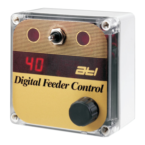
DIGITAL CONTROL INSTALLATION & OPERATION: 1 The Digital Feeder Control from ATL Agricultural Technology offers a most elegant and yet However, the opposite side feeder can be set to run by pressing the Feed Switch but it will not simple way of feeding in parlour. deliver the ration displayed since it is working in stand-by mode, running just so long as the It is connected to either a single feeder, an ATL Abreast Feeder with automatic feed flaps or two Feed Switch is held over. -
Page 4: Installation
DIGITAL CONTROL INSTALLATION & OPERATION: 2 Installation Diode connection across motor terminals. Power Supplies or Interfaces must be provided with a clean 230volt mains supply. Avoid The positive end of the diode is marked sharing an outlet with another load. Use a switched, fused outlet not a 13Amp plug and socket. with a band;... -
Page 5: Electric Feeders
DIGITAL CONTROL INSTALLATION & OPERATION: 3 Electric Feeders. The Global Timing Pulse. For electric feeders the jumper must be positioned as shown in Figure (1). A broad indication of A powerful feature of the Digital Feeder Control system is the Global Timing Pulse. A single cable running time per 500grms of feed delivered for motorised feeders is: links all of the Controls to a common timing pulse to ensure that all are running to the same clock period. - Page 6 DIGITAL CONTROL INSTALLATION & OPERATION: 4 Single Feeder Connection: No Connection: 10 No Connection: 9 (+) DC 12volts to Feeder or Solenoid/ Pin 3: 8 (+) DC 12volts from Power Supply: 7 (-) DC 12volts from Power Supply: 6 (-) DC 12volts to Feeder or Solenoid: 5 No Connection: 4 Connect to pin 8: 3 No Connection: 2...
- Page 7 DIGITAL CONTROL INSTALLATION & OPERATION: 5 ATL Power Supply 12volt Single Feeder: Herringbone Parlour Connections Figures in square brackets refer to minimum cable csa (mm ). Fuse: 1 Inch ‘Mains’ 230volts AC(L) Earth(E) Neutral(N) Timing Pulse Fuse: 20mm x T2Amp Replacing Old Dial Up (Mechanical) controls with Electronic Digital Controls Connector Output Number...
- Page 8 DIGITAL CONTROL INSTALLATION & OPERATION: 6 ATL Power Supply 12volt Double Control: Herringbone Parlour Connections Figures in square brackets refer to minimum cable csa (mm ). Fuse: 1 Inch ‘Mains’ 230volts AC(L) Earth(E) Neutral(N) Timing Pulse Fuse: 20mm x T2Amp Connector Output Number (see page 4) Digital Feeder Control...
- Page 9 DIGITAL CONTROL INSTALLATION & OPERATION: 7 ATL Power Supply 12volt Digital Control: Abreast Parlour Connections Figures in square brackets refer to minimum cable csa (mm ). Fuse: 1 Inch ‘Mains’ 230volts AC(L) Earth(E) Neutral(N) Feeder motor and connector block. The ballast resistor and diode Timing Pulse Fuse: 20mm x T2Amp are factory fitted.
-
Page 10: Power Supply And Atl Control Power Supply
DIGITAL CONTROL INSTALLATION & OPERATION: 8 12volt Feeder Connections using existing 12volt Power Supply and ATL Control Power Supply. Figures in square brackets refer to minimum cable csa (mm2 ). ATL Control Existing 12v Power Supply Power Supply Output: 12volts AC or DC 12volts AC or DC to ATL Control Power Supply [2.5] Digital Feeder Control Feeder Motor... - Page 11 DIGITAL CONTROL INSTALLATION & OPERATION: 9 12volt Feeder Connections using ATL Digital Power Supply (either 4pt/8pt/12pt) with Global Timing Pulse Heat Sink: LIVE at Input Voltage Negative Blue 17.5v AC Input (Regulator Supply) Thermal Cutout 18 - 24v DC Input Red 20 or 30 Amp Auto Fuse (Feeders) Fuse: 1 Inch ‘Mains’...
-
Page 12: Supply With Global Timing Pulse
DIGITAL CONTROL INSTALLATION & OPERATION: 10 ATL Feeder Connections using ATL Control Only Power Supply with Global Timing Pulse. Disconnect mains supply before removing cover. Control Supply Transformer: 0-12: 0-12: 25VA Do not drill fixing or cable 230v AC Primary entry holes in the top or sides of the casing. -
Page 13: Fault Finding
DIGITAL CONTROL INSTALLATION & OPERATION: 11 The Digital Feeder Control Fault Finding Scheme Digital Feeder Control Faults Symptom Possible Cause Solution Feeding LED’s fail to illuminate Feeder jam Check for feeder jam Display flashes continuously Short circuit Check for short circuit Turn dial to zero ‘00’... - Page 14 DATA SHEET: 08A DIGITAL CONTROL CONVERSION Digitial Controls: Conversion from Mechanical Version to Electronic Version: DOUBLE CONTROLS: Old Mechanical Double Control New Digital Double Control Connections: Terminate The cable colors are for clarity only and are not significant. SINGLE CONTROLS: Old Mechanical Single Control New Digital Single Control Connections: Terminate...
-
Page 15: No Connection
DATA SHEET: 08B DIGITAL CONTROL CONVERSION Digital Feeder Control: 12-24v AC Version 12-24vAC Feeder Supply 12-24vAC Feeder Supply COM: Common: To Feeder Power supply Connect to 1 screw only NO: Normally Open: To one side of motor Connect to 1 screw 16A Relay: Single Pole Changeover: 12 volt coil unless stated Relay Coil: From Digital Control: Make both screw connections as shown... -
Page 16: No Connection
DATA SHEET: 08C DIGITAL CONTROL CONVERSION The AC interface may also be used with existing power Digital Control 24volt AC Interface for Existing Power Supplies The ATL 24volt AC Power Supply Interface converts the supplies sourcing 24volts DC. and should be connected in 24volt AC output from an existing power supply and precisely the same way. - Page 17 DATA SHEET: 08D DIGITAL CONTROL CONVERSION Digital Control Only Power Supply: Digital Controls driving Westfalia 24v Feeders: Existing 24vAC WS Supply for feeders. Disconnect mains supply before removing cover. Control Supply Transformer: 0-12: 0-12: 25VA Do not drill fixing or cable 230v AC Primary entry holes in the top or sides of the casing.
- Page 18 DATA SHEET: 23A DIGITAL CONTROL WS RESISTOR FITTED 24volt Feeder Connections using Existing 24volt Power Supply and ATL Control Power Supply. WestFalia ‘M’ type feeder WITH integral ballast resistor. Figures in square brackets refer to minimum cable csa (mm2 ). ATL Control Existing 24v Power Supply Power Supply...
- Page 19 DATA SHEET: 23B DIGITAL CONTROL WS NO RESISTOR 24volt Feeder Connections using Existing 24volt Power Supply and ATL Control Power Supply. WestFalia ‘M’ type feeder WITHOUT integral ballast resistor. Figures in square brackets refer to minimum cable csa (mm2 ). Existing 24v Power Supply ATL Control Output: 24volts AC or DC...
Need help?
Do you have a question about the 39-0050 and is the answer not in the manual?
Questions and answers