ATI Technologies Q46 Series O & M Manual
Dissolved oxygen monitor
Hide thumbs
Also See for Q46 Series:
- Manual (65 pages) ,
- Communications manual (23 pages) ,
- Profibus communication manual (21 pages)
Table of Contents
Advertisement
Dissolved Oxygen Monitor
Home Office
Analytical Technology, Inc.
6 Iron Bridge Drive
Collegeville, PA 19426
Phone: 800-959-0299
610-917-0991
Fax:
610-917-0992
Email: sales@analyticaltechnology.com
O & M Manual
Model Q46D/60
European Office
ATI (UK) Limited
Unit 1 & 2 Gatehead Business Park
Delph New Road, Delph
Saddleworth OL3 5DE
Phone: +44 (0)1457-873-318
Fax:
+ 44 (0)1457-874-468
Email: sales@atiuk.com
Advertisement
Table of Contents

Related Manuals for ATI Technologies Q46 Series


Summary of Contents for ATI Technologies Q46 Series
- Page 1 O & M Manual Model Q46D/60 Dissolved Oxygen Monitor Home Office European Office Analytical Technology, Inc. ATI (UK) Limited 6 Iron Bridge Drive Unit 1 & 2 Gatehead Business Park Collegeville, PA 19426 Delph New Road, Delph Phone: 800-959-0299 Saddleworth OL3 5DE 610-917-0991 Phone: +44 (0)1457-873-318 Fax:...
-
Page 2: Table Of Contents
Table of Contents PART 1 - INTRODUCTION ........ 4 PART 7 – CALIBRATION ....... 43 General ..........4 Oxygen Calibration ......43 Standard System ......... 4 7.11 Oxygen Span Cal ......43 Features ..........4 7.12 D.O. Span Cal (1-spl) ....43 7.13 D.O. - Page 3 Table of Figures 1 – Q46 E ................8 IGURE NCLOSURE IMENSIONS 2 - W ................. 9 IGURE ALL OR IPE MOUNT BRACKET 3 - W ................10 IGURE OUNTING IAGRAM 4 - P ................10 IGURE OUNTING IAGRAM 5 - P ................
-
Page 4: Part 1 - Introduction
Part 1 - Introduction General The Model Q46D is a versatile on-line monitoring system designed for the continuous measurement of dissolved oxygen in solution. The full scale operating range of the system 0-40 ppm, and the sensing system will operate on water streams with temperatures ranging from 0 to 50C. - Page 5 Q46D Dissolved Oxygen System Part 1 - Introduction • Units provide provides three SPDT relay outputs and two isolated analog outputs. Software settings for relay control include setpoint, deadband, phase, delay, and failsafe. • Selectable Output Fail Alarm feature on Relay C allows system diagnostic failures to be sent to external monitoring systems.
-
Page 6: Q46D/60 System Specifications
Q46D Dissolved Oxygen System Part 1 - Introduction Q46D/60 System Specifications Displayed Parameters Main input, 0.1 ppm to 40.0 ppm %Saturation, 0 to 999.9% Sensor temperature, -10.0 to 50.0°C (23 to 122ºF) Sensor signal, -40 to +2000 mVDC Loop current, 4.00 to 20.00 mA Sensor slope/offset Model number and software version PID Controller Status... -
Page 7: Q46D Performance Specifications
Q46D Dissolved Oxygen System Part 1 - Introduction Filter Adjustable 0-9.9 minutes to 90% input step change Temperature Input Pt1000 RTD with automatic compensation Ambient Humidity 0 to 95%, indoor/outdoor use, non-condensing to rated ambient temperature range Altitude Up to 2000 m (6562 ft) Electrical Certification Ordinary Location, cCSAus (Certified to both CSA and UL standards), pollution degree 2, installation category 2... -
Page 8: Part 2 - Analyzer Mounting
Part 2 – Analyzer Mounting General All Q46 Series instruments offer maximum mounting flexibility. A bracket is included with each unit that allows mounting to walls or pipes. In all cases, choose a location that is readily accessible for calibrations. Also consider that it may be necessary to utilize a location where solutions can be used during the calibration process. -
Page 9: Wall Or Pipe Mount
Part 2 – Analyzer Mounting Q46D Dissolved Oxygen System Wall or Pipe Mount A PVC mounting bracket with attachment screws is supplied with each transmitter (see Figure for dimensions). The multi-purpose bracket is attached to the rear of the enclosure using the four flat head screws. -
Page 10: Figure 3 - Wall Mounting
Part 2 – Analyzer Mounting Q46D Dissolved Oxygen System Figure 3 - Wall Mounting Diagram MENU ENTER Figure 4 - Pipe Mounting Diagram O&M Manual Rev-N (4/21) -
Page 11: Panel Mount, Ac Powered Monitor
Part 2 – Analyzer Mounting Q46D Dissolved Oxygen System Panel Mount, AC Powered Monitor Panel mounting of an AC powered monitor uses the panel mounting flange molded into the rear section of the enclosure. Figure 5 provides dimensions for the panel cutout required for mounting. -
Page 12: Part 3 - Sensor Mounting
Part 3 – Sensor Mounting General Select a location within the maximum sensor cable length for mounting of the sensor. Locating the sensor within 25 ft. of the transmitter is generally preferred for ease of operation and calibration. Submersion Mounting Most applications for D.O. -
Page 13: Flowcell Mounting
Part 3 – Sensor Mounting Q46D Dissolved Oxygen System Flowcell Mounting For applications requiring measurement in a flowing water line, a flowcell assembly and a flow- type sensor should be used. Two types of flowcell are available. Applications that allow an open flow system can best be satisfied using the 00-0043 constant-head flowcell. -
Page 14: Sealed Flowcell
Part 3 – Sensor Mounting Q46D Dissolved Oxygen System Sealed Flowcell Applications where the sample inlet flow is well controlled can use a simpler sealed flowcell. Using this flowcell requires that flow be controlled externally to about 400 cc/min. Variable flow rate or variable pressure will cause unstable readings in this flowcell. -
Page 15: Part 4 - Electrical Installation
Part 4 – Electrical Installation General The Q46 is powered in one of two ways, depending on the version purchased. The 12-24 VDC powered analyzer requires a customer supplied DC power supply. The 90-260 VAC version requires line power. Please verify the type of unit before connecting any power. WARNING Do not connect AC line power to the DC version. - Page 16 Part 4 – Electrical Installation Q46D Dissolved Oxygen System WARNING Disconnect line power voltage BEFORE connecting line power wires to Terminal TB5 of the power supply. The power supply accepts only standard three-wire single phase power. The power supply is configured for 115 VAC or 230 VAC operation at the factory at time of order, and the power supply is labeled as such.
-
Page 17: Relay Connection
Part 4 – Electrical Installation Q46D Dissolved Oxygen System Relay Connection Three SPDT relays are provided on the power supply board. None of the relay contacts are powered. The user must supply the proper power to the contacts. For applications that require the same switched operating voltage as the Q46 (115 or 230 V), power may be jumped from the power input terminals at TB7. -
Page 18: Optional Output/Relay Connection
Part 4 – Electrical Installation Q46D Dissolved Oxygen System Optional Output/Relay Connection TB2, is used to connect to the optional 3-relay card (Figure 11) OR the optional third analog output Out#3, (Figure 13). The Q46 can be configured for only one of these optional features, and the hardware for either option must be factory installed. -
Page 19: Sensor Wiring
Part 4 – Electrical Installation Q46D Dissolved Oxygen System Sensor Wiring The sensor cable can be quickly connected to the Q46 terminal strip by matching the wire colors on the cable to the color designations on the label in the monitor. A junction box is also available to provide a break point for long sensor cable runs. -
Page 20: Direct Sensor Connection
Part 4 – Electrical Installation Q46D Dissolved Oxygen System Direct Sensor Connection The sensor cable can be routed into the enclosure through one of cord-grips supplied with the unit. Routing sensor wiring through conduit is only recommended if a junction box is to be used. Some loose cable is needed near the installation point so that the sensor can be inserted and removed easily from the flowcell. -
Page 21: Junction Box Connection
Part 4 – Electrical Installation Q46D Dissolved Oxygen System Junction Box Connection For installations where the sensor is to be located more than 25 feet from the monitor (max. 100 feet), a junction box must be used. The junction box is shown in Figure 15 - Junction Box Interconnect Wiring, and is supplied with a ½"... -
Page 22: Part 5 - Sensor Assembly
Part 5 – Sensor Assembly Oxygen Sensor Preparation The oxygen sensor supplied with the Q46D is shipped dry. It will not operate until it is prepared by adding electrolyte and a membrane. Preparation of the sensor for operation must be done carefully. -
Page 23: Figure 17 - Submersible
Part 5 – Sensor Assembly Q46D Dissolved Oxygen System Figure 17 - Submersible Sensor Module Exploded View Follow the procedure below to prepare the D.O. sensor module for operation: 1. Unscrew the electrolyte chamber from the assembled sensor and also remove the vent screw from the side of the sensor body. -
Page 24: Flow Type D.o. Sensor
Part 5 – Sensor Assembly Q46D Dissolved Oxygen System The sensor is now ready for operation. The membrane should be stretched tightly across the tip of the sensor. CAUTION: When handling the assembled sensor, do not set the sensor on its tip or damage to the membrane will result. -
Page 25: Part 6 - Configuration
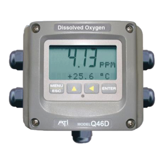
Part 6 – Configuration User Interface The user interface for the Q46 Series instrument consists of a custom display and a membrane keypad. All functions are accessed from this user interface (no internal jumpers, pots, etc.). When power is first applied, you may notice that the display does not come on immediately. This is normal. -
Page 26: 6.11 Keys
Q46D Dissolved Oxygen System Part 6 - Configuration 6.11 Keys All user configurations occur through the use of four membrane keys. These keys are used as follows: MENU/ESC To scroll through the menu section headers or to escape from anywhere in software. -
Page 27: Software
Q46D Dissolved Oxygen System Part 6 - Configuration Icon Area The icon area contains display icons that assist the user in set-up and indicate important states of system functions. The CAL, CONFIG, and DIAG icons are used to tell the user what branch of the software tree the user is in while scrolling through the menu items. -
Page 28: Software Navigation
Q46D Dissolved Oxygen System Part 6 - Configuration 6.21 Software Navigation Within the CAL, CONFIG, CONTROL, and DIAG menu sections is a list of selectable items. Once a menu section (such as CONFIG) has been selected with the MENU key, the user can access the item list in this section by pressing either the ENTER key or the UP arrow key. -
Page 29: Figure 20 - Software Map
Q46D Dissolved Oxygen System Part 6 - Configuration Start MENU MENU MENU MENU MENU MENU MEASURE CONFIG CONTROL DIAG SECTIONS (display only) ENTER ENTER ENTER ENTER Temperature Entry Lock Cal D.O. PID 0% #1 Set Hold PID 100% #1 Fault List Set Delay Cal Temp PID % Output... -
Page 30: Measure Menu [Measure]
Q46D Dissolved Oxygen System Part 6 - Configuration 6.22 Measure Menu [MEASURE] The default menu for the system is the display-only menu MEASURE. This menu is a display-only measurement menu and has no changeable list items. When left alone, the instrument will automatically return to this menu after approximately 30 minutes. -
Page 31: Calibration Menu [Cal]
Q46D Dissolved Oxygen System Part 6 - Configuration Tcyc 24.0 hr Automatic sensor cleaning frequency (displayed only when enabled by programming relay B for Cln1 or Cln2). Note: A display test (all segments ON) can be actuated by pressing and holding the ENTER key while viewing the model/version number on the lower line of the display. - Page 32 Q46D Dissolved Oxygen System Part 6 - Configuration Contrast This function sets the contrast level for the display. The custom display is designed with a wide temperature range and contains an LED back light so that the display is can be seen in the dark. Press ENTER to initiate user entry mode, and the value will flash.
- Page 33 Q46D Dissolved Oxygen System Part 6 - Configuration For ultrapure water applications, set this value to 0.00. For sea water applications, set this value to 53.00. Timer Funcs Enables the Autocleaner Logic on Relays D, E, and F. When enabled, these auxiliary relays control the remote autocleaner enclosure.
-
Page 34: Control Menu [Control]
Q46D Dissolved Oxygen System Part 6 - Configuration The FAIL setting enables the fail alarm mode for Relay A. Relay A will then trip on any condition that causes the FAIL icon to be displayed on the LCD. Using this mode allows the User to send alarm indications to other remote devices. - Page 35 Q46D Dissolved Oxygen System Part 6 - Configuration though the controller can achieve 0% or 100% anywhere within the range.) If the 0% point is lower than the 100% point, then the controller action will be “reverse” acting. That is, the output of the controller will increase if the measured value is less than the setpoint, and the output will decrease if the measured value is larger than the setpoint.
- Page 36 Q46D Dissolved Oxygen System Part 6 - Configuration arrow keys to select the desired numerical value. Press ENTER to store the new value. *Set 4 mA #2 These functions set the second 4 mA and 20 mA current loop output *Set 20 mA #2 points for the transmitter.
-
Page 37: Figure 21 - Control Relay
Q46D Dissolved Oxygen System Part 6 - Configuration indicator illuminates when the oxygen level drops below the setpoint. The failsafe setting does have an impact on this logic. The description here assumes the failsafe setting is OFF. Press ENTER to initiate user entry mode, and the entire value will flash. -
Page 38: Figure 22 - Alarm Relay
Q46D Dissolved Oxygen System Part 6 - Configuration Settings: Setpoint A-HI: 1.000 ppm Setpoint A-LO: .500 ppm Hyst A-HI: 0.050 Hyst A-LO: .0.050 Delay A-HI: 000 Delay A-LO: 000 Figure 22 - Alarm Relay Example If Relay B Mode is set to CON, then Relay B will function identically to B Setpoint Relay A. -
Page 39: Diagnostics Menu [Diag]
Q46D Dissolved Oxygen System Part 6 - Configuration additional 3 minutes (HOLD time), retaining the original output signals. Once the 3 minutes expire, the outputs will be released back to the Then, the entire cycle will repeat – normal monitoring state. approximately once per day. - Page 40 Q46D Dissolved Oxygen System Part 6 - Configuration Faults are not stored; therefore, they are immediately removed if power is cycled. If the problem causing the faults still exists, however, faults will be displayed again after power is re-applied and a period of time elapses during which the diagnostic system re-detects them.
- Page 41 Q46D Dissolved Oxygen System Part 6 - Configuration Fail Val #1 Sets the output failure value for Iout#1. When Fail Out above is set to ON, this function sets value of the current loop under a FAIL condition. When the Relay Option Board is installed, the display will read Fail Out #1.
- Page 42 Q46D Dissolved Oxygen System Part 6 - Configuration *Failsafe This function allows the user to set the optional system relays to a failsafe condition. In a failsafe condition, the relay logic is reversed so that the relay is electrically energized in a normal operating state. By doing this, the relay will not only change state when, for example, an oxygen limit is exceeded, but also when power is lost to the controller.
-
Page 43: Part 7 - Calibration
Q46D Dissolved Oxygen System Part 7 - Calibration Part 7 – Calibration Oxygen Calibration Once power is applied, the sensor must be given time to stabilize. This is best done by following the zeroing procedure below. Establishing a stable zero is critical to the proper operation of the monitor. -
Page 44: Air Span Cal (% Sat)
Q46D Dissolved Oxygen System Part 7 - Calibration 6. If the data remains unstable for 10 minutes, the calibration will fail and the message Cal Unstable will be displayed. 7. The screen will display the last measured ppm value and a message will be displayed prompting the user for the lab value. -
Page 45: 7.14 Dissolved Oxygen Zero Cal
Q46D Dissolved Oxygen System Part 7 - Calibration The system now begins acquiring data for the calibration value. As data is gathered, the units for ppm and temperature may flash. Flashing units indicate that this parameter is unstable. The calibration data point acquisition will stop only when the data remains stable for a pre- determined amount of time (approximately 15-20 seconds.) This can be overridden by pressing ENTER. -
Page 46: Temperature Calibration
Q46D Dissolved Oxygen System Part 7 - Calibration If the data remains unstable for 10 minutes, the calibration will fail and the message Cal Unstable will be displayed. If accepted, the screen will display the message PASS with the new sensor zero reading (offset), then it will return to the main measurement display. -
Page 47: Part 8 - Pid Controller Details
Part 8 – PID Controller Q46D Dissolved Oxygen System Part 8 – PID Controller Details PID Description PID control, like many other control schemes, is used in chemical control to improve the efficiency of chemical addition or control. By properly tuning the control loop that controls chemical addition, only the amount of chemical that is truly required is added to the system, saving money. - Page 48 Part 8 – PID Controller Q46D Dissolved Oxygen System The most notable feature of the algorithm is the fact the proportional gain term affects all components directly (unlike some other algorithms - like the “series” form.) If a pre-existing controller utilizes the same form of the algorithm shown above, it is likely similar settings can for made if the units on the settings are exactly the same.
-
Page 49: Classical Pid Tuning
Part 8 – PID Controller Q46D Dissolved Oxygen System Classical PID Tuning Unlike many high speed position applications where PID loops are commonly used, the chemical feed application employed by this instrument does not require intense mathematical exercise to determine tuning parameters for the PID. In fact, the risk of instability is far greater with overly tuned PID control schemes. - Page 50 Part 8 – PID Controller Q46D Dissolved Oxygen System The easiest process’ to control with closed-loop schemes are generally linear, and symmetrical, in nature. For example, controlling level in tank where the opening of valve for a fixed period of time corresponds linearly to the amount that flows into a tank.
-
Page 51: Part 9 - System Maintenance
Part 9 – System Maintenance Q46D Dissolved Oxygen System Part 9 – System Maintenance General The Q46D/60 Dissolved Oxygen System will generally provide unattended operation over long periods of time. With proper care, the system should continue to provide measurements indefinitely. -
Page 52: 9.32 Pressure Compensator Rebuild
Part 8 – PID Controller Q46D Dissolved Oxygen System lead electrode around the post and replace the nut and washer. Tighten the nut firmly but do not over tighten as damage to the sensing module can result. Wrap the remainder of the lead around the sensor body. -
Page 53: Part 10 - Troubleshooting
Part 10 – Troubleshooting 10.1 General The information included in this section is intended to be used in an attempt to quickly resolve an operational problem with the system. During any troubleshooting process, it will save the most time if the operator can first determine if the problem is related to the analyzer, sensor, or some external source. -
Page 54: Analyzer
Q46D Dissolved Oxygen System Part 10 - Troubleshooting On relay based systems, check the load that is connected to the relay contacts. Verify the load is within the contact rating of the relays. Relay contacts which have been used for higher power AC current loads may become unsuitable for very low signal DC loads later on because a small amount of pitting can form on the contacts. -
Page 55: Display
Q46D Dissolved Oxygen System Part 10 - Troubleshooting 10.31 Display Messages The Q46 Series instruments provide a number of diagnostic messages which indicate problems during normal operation and calibration. These messages appear as prompts on the secondary line of the display or as items on the Fault List. -
Page 56: Sensor
Q46D Dissolved Oxygen System Part 10 - Troubleshooting MESSAGE DESCRIPTION POSSIBLE CORRECTION D.O. Cal Fail Failure of oxygen calibration. FAIL icon will Clean sensor redo zero and span calibration. not extinguish until successful calibration If still failure, sensor slope may be less than has been performed, or 30 minutes passes 20% or greater than 500%. -
Page 57: Figure 25 - P T 1000 Rtd R
Q46D Dissolved Oxygen System Part 10 - Troubleshooting Remove the front sensor “cartridge” for the sensor body by unscrewing the cartridge at the large “knurl” in a counterclockwise manner. Inspect the gold RCA jack for signs of moisture or other foulants. -
Page 58: Figure 26 - Reference , B
Q46D Dissolved Oxygen System Part 10 - Troubleshooting If you suspect that water has gotten into a cable connection or into the plug connection of a submersible sensor, disconnect the cable and allow the parts of the sensor to sit in a warm place for 24 hours. If water in the connector is the problem, it should dry out sufficiently to allow normal sensor operation. - Page 59 Q46D Dissolved Oxygen System Part 10 - Troubleshooting Water Saturated Concentration of O Temperature Temperature °F °C °F °C 14.6 23.3 14.1 24.4 13.7 25.6 13.3 26.7 12.9 27.8 12.6 28.9 12.2 30.0 11.9 31.1 11.6 32.2 10.0 11.3 33.3 11.1 11.0 34.4...
-
Page 60: Spare Parts
Spare Parts Part No. Description 03-0393 Q46D Front Lid electronics assembly 07-0320 AC Powered monitor electronics assembly, 100-240 VAC 07-0321 DC Powered monitor electronics assembly 12-24 VDC 07-0322 AC Powered monitor electronics assembly w/Profibus, 100-240 VAC 07-0323 DC Powered monitor electronics assembly w/Profibus, 12-24 VDC 03-0407 P/S Assy, 100-240 VAC 03-0408... - Page 61 Q46D Dissolved Oxygen System Part 10 - Troubleshooting 00-1522 Sealed Flowcell Assembly 05-0101 Sealed Flowcell Vacuum Breaker Note: Instrument is supplied with sufficient spare parts for 12 months of operation. For 2 year spare parts inventory, 1 each of the items marked with an asterisk are required. Lock/Unlock Code: 1463 O&M Manual Rev-N (4/21)
- Page 62 PRODUCT WARRANTY Analytical Technology, Inc. (Manufacturer) warrants to the Customer that if any part(s) of the Manufacturer's equipment proves to be defective in materials or workmanship within the earlier of 18 months of the date of shipment or 12 months of the date of start-up, such defective parts will be repaired or replaced free of charge.
- Page 63 WATER QUALITY MONITORS GAS DETECTION PRODUCTS Dissolved Oxygen Ammonia Carbon Monoxide Free Chlorine Hydrogen Combined Chlorine Nitric Oxide Total Chlorine Oxygen Residual Chlorine Dioxide Cl2 Phosgene Potassium Permanganate Bromine Chlorine Dissolved Ozone Chlorine Dioxide pH/ORP Fluorine Conductivity Iodine Hydrogen Peroxide Acid Gases Peracetic Acid O Ethylene Oxide...
Need help?
Do you have a question about the Q46 Series and is the answer not in the manual?
Questions and answers