Table of Contents
Advertisement
Quick Links
SmartTach
SmartTach
SmartTach
SmartTach
TEL: (248) 848-9200 FAX: (248) 848-9016
SmartTach Operating Manual
Universal Speed
Universal Speed
Universal Speed
Universal Speed
Measurement Tool
Measurement Tool
Measurement Tool
Measurement Tool
USER MANUAL
47199 Cartier Drive
Wixom, Michigan 48393 U.S.A.
CONTENTS
Page i
Advertisement
Table of Contents

Related Manuals for ATI Technologies SmartTachSmartTach


Summary of Contents for ATI Technologies SmartTachSmartTach
- Page 1 CONTENTS SmartTach SmartTach SmartTach SmartTach Universal Speed Universal Speed Universal Speed Universal Speed Measurement Tool Measurement Tool Measurement Tool Measurement Tool USER MANUAL 47199 Cartier Drive Wixom, Michigan 48393 U.S.A. TEL: (248) 848-9200 FAX: (248) 848-9016 SmartTach Operating Manual Page i...
- Page 2 CONTENTS Documentation Revision 1.3 Copyright 1992-1998 by Accurate Technologies Inc. All rights reserved. Printed in the United States of America Information in this documentation is subject to change without notice and does not represent a commitment on the part of Accurate Technologies Inc. No part of this manual may be reproduced or transmitted in any form or by any means, electronic or mechanical, including photocopying, recording, or information storage or retrieval systems, for any purpose other than the purchaser's personal use, without the express written permission of Accurate Technologies Inc.
-
Page 3: Table Of Contents
CONTENTS INTRODUCTION Introduction....................... 1-2 About this Manual..................... 1-4 Technical Support..................... 1-4 Get to Know SmartTach ................... 1-5 SmartTach Connections ..................1-5 Important Safety Warnings..................1-6 INSTALLATION General Information....................2-2 Placement of the SmartTach Unit................2-2 Selecting the DC Power Source ................2-2 Pulse Input Connection .................... - Page 4 CONTENTS 04 - Engineering Unit Conversion Factor ..............4-6 05 - Engineering Conversion Units................4-7 06 - Input Signal Conditioning Select ............... 4-8 07 - Low-Pass Filter Count..................4-9 08 - Multi-Strike Filter ..................... 4-10 09 - Pulses per Measurement ................4-11 10 - Spark Input Threshold Level ................
- Page 5 CONTENTS Display Maximum/Minimum Attained Values ............5-2 Pushbutton Switch Functions ................... 5-3 Measure Mode ...................... 5-3 Using other Instruments with the Analog Output Signal ........... 5-4 Using Range Outputs ....................5-4 Range Output Example 1..................5-5 Range Output Example 2..................5-6 TROUBLESHOOTING General Information....................
- Page 6 CONTENTS LIST OF FIGURES Figure 1 - 1: Front and Rear Panels ................1-5 Figure 2 - 1: Spark Input Examples ................2-3 Figure 2 - 2: Trigger Input Examples ................2-3 Figure 3 - 1: Parameter Group Display ................ 3-3 Figure 3 - 2: Parameter List Display ................
-
Page 7: Introduction
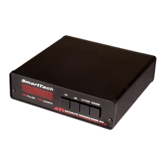
Chapter Introduction Introduction Introduction Introduction... - Page 8 INTRODUCTION Introduction Congratulations on the acquisition of your new SmartTach Universal Speed Measurement Tool! The SmartTach is a precision speed measurement instrument designed specifically for the development and testing environment. Among its many innovations is the capability to continuously measure speed form virtually any type of signal.
- Page 9 INTRODUCTION them. We feel that customer participation is the ultimate way to providing the best possible products. SmartTach Operating Manual Page 1-3...
-
Page 10: About This Manual
INTRODUCTION About This Manual This manual was written from the perspective of an engine test engineer/technician. General knowledge of internal combustion engines, ignition systems, and engine control modules is assumed. No presentation of engine or ignition system theory is made further than is necessary to install and operate the SmartTach. -
Page 11: Get To Know Smarttach
INTRODUCTION Get to Know SmartTach Prior to installation or operation of SmartTach, we strongly encourage you to spend a few minutes and study the diagram below while examining the unit to get to know its characteristics. Front Panel S m a r tT a c h ENTER MODE 2 3 5 0 r p m PULSE... -
Page 12: Important Safety Warnings
INTRODUCTION Important Safety Warnings !" NEVER WORK ON OR AROUND A RUNNING ENGINE. !" It is the responsibility of the installer of SmartTach to comply with the National Electrical Code and any other applicable Federal, State, or local safety codes. !"... - Page 13 INTRODUCTION SmartTach Operating Manual Page 1-7...
- Page 15 Chapter Installation Installation Installation Installation...
-
Page 16: Installation General Information
INSTALLATION General Information The SmartTach is a flexible engineering tool designed to be compatible with practically all automotive-type engines and ignition systems. Therefore, the specific installation procedure is largely dependent on the application. The following general steps are typically involved in the installation and setup of the SmartTach: #"... -
Page 17: Pulse Input Connection
INSTALLATION The unit does not have a built-in power switch. To avoid unnecessary power drain (especially in a vehicle), the power should be disconnected when the unit is not in use. This can be done easily in a vehicle by using the Switched-Ignition or Accessory power sources normally available at the fuse block. -
Page 18: Tachsensor Connection
INSTALLATION TachSensor Connection This connection is for use with the optional TS1 TachSensor. This connection also functions as the I/O port for access to other signals (refer to the I/O Port connection section for details on these functions). When using the TachSensor make sure that nothing is connected to the PULSE INPUT connection. -
Page 19: Analog Output Connection
INSTALLATION Analog Output Connection The SmartTach precision analog output can be used to send real-time speed information to a test cell computer, data acquisition system, strip- chart recorder, etc. This output voltage is generated by a precision 12-bit digital-to-analog converter (output accuracy is ±0.005 volts). The update rate and low-pass filtering of this output are programmable using the configuration parameters. -
Page 20: I/O Port Connection
INSTALLATION 9 - RNG Output (Ring Indicator) Note: Pins 1, 6, and 8 are internally connected. Pins 7 and 9 are not used and not connected. I/O Port Connection In addition to the TachSensor connection, this port also provides access to several other SmartTach I/O signals. - Page 21 Chapter Configuration Configuration Configuration Configuration...
-
Page 22: Configuration General Information
CONFIGURATION General Information The SmartTach is a very flexible speed measurement system. To provide compatibility with practically all types of speed measurement, a wide variety of programmable parameters are incorporated into the unit. The configuration parameters effectively "customize" the unit to each specific application. -
Page 23: Configure
CONFIGURATION Configure This operating mode displays the configuration parameters or parameter groups (one at a time) on the built-in display. This mode is used to select the desired configuration parameter to be displayed and/or changed. All measurement operations are suspended when in this mode. Default Configuration Values The SmartTach has internal default settings for all of the configuration parameter values. -
Page 24: Using The Pushbutton Switches
CONFIGURATION The display format in this mode is XX>YYYYY where XX=Parameter Item Number and YYYYY=Current Value. Using the Pushbutton Switches The four built-in Pushbutton switches are used to access the various configuration parameters and make any necessary changes. function of each switch depends on the current operating mode (as indicated by the LED lights on the front panel). -
Page 25: Changing Parameters
CONFIGURATION S m a r tT a c h ENTER MODE Parameter Edit > E n g S p PULSE CONFIG Display: Parameter Id and Current Value. : Scroll Parameter Value Down A flashing > symbol indicates edit mode. : Scroll Parameter Value Up PULSE: Flashing (if pulses are being received) ENTER: Accept New Value CONFIG: On... -
Page 26: Figure 3 - 4: Parameter Edit Navigation
CONFIGURATION Figure 3 - 4: Parameter Edit Navigation Page 3-6 SmartTach Operating Manual... -
Page 27: Configuration Examples
CONFIGURATION Configuration Examples These are just a few examples of SmartTach configurations and the required parameter settings. Only required parameters are listed. Configuration Example 1 Engine RPM measurement with a distributor type ignition system using a inductive pickup on a single spark plug wire. Analog output configured to 1volt/1000 rpm, 0 - 10,000 rpm range and 1ms update rate. -
Page 28: Configuration Example 3, 4
CONFIGURATION Configuration Example 3 Engine RPM measurement on a QUAD 4 engine with a distributorless ignition system using the TachSensor on the igintion module power wire (pink). Analog output configured to 1volt/1000 rpm, 0 - 10,000 rpm range and 1ms update rate. Parameter Parameter ID Parameter... - Page 29 CONFIGURATION SmartTach Operating Manual Page 3-9...
-
Page 31: Parameters
Chapter Parameters Parameters Parameters Parameters... -
Page 32: Measurement Parameter
PARAMETERS 00 - Measurement Parameter Parameter Group: Setup! Options: - Engine Speed EngSp - Vehicle Speed VehSp - Dynamometer Roll Speed DynSp - Signal Frequency Freq - Period of the Signal - Pulsewidth - Duty Cycle Duty% - Auxillary Input Voltage Vaux Default: EngSp... -
Page 33: Displayed Engineering Units
PARAMETERS 01 - Displayed Engineering Units Parameter Group: Setup! Options: - Engine Speed (Parm 00 set to EngSp) RPM, RPS MPH, KPH - Vehicle Speed (Parm 00 set to VehSp) MPH, KPH - Dyno Speed (Parm 00 set to DynSp) - Frequency (Parm 00 set to Freq) Hz, kHz... -
Page 34: Patterns/Pulses Per Cam/Dyno Revolution
PARAMETERS 02 - Patterns/Pulses per Cam/Dyno Revolution Parameter Group: Setup! Range: 1-9999 pulses Increment: 1 pulse Default: 1 pulse Purpose: This parameter used calculate Engine Chassis Dynamometer speed. This parameter is required and if not set correctly will result in improper measurements. How to Set: Before setting this parameter you must know if the signal is a pattern of pulses or a single pulse that repeats. -
Page 35: Pulses Per Pattern
PARAMETERS 03 - Pulses per Pattern Parameter Group: Setup! Range: 1-60 pulses Increment: 1 pulse Default: 1 pulse Purpose: This parameter is used to specify the number of pulses per pattern. How to Set: With a pattern type signal this parameter should be set to the number of pulses per pattern. -
Page 36: Engineering Unit Conversion Factor
PARAMETERS 04 - Engineering Unit Conversion Factor Parameter Group: Setup! Range: 1-9999 - Vehicle Speed (Parm 00 set to VehSp) 0.01-99.99 - Dyno Speed (Parm 00 set to DynSp) Increment: 1 - Vehicle Speed (Parm 00 set to VehSp) 0.01in or 1mm - Dyno Speed (Parm 00 set to DynSp) Default: - Vehicle Speed (Parm 00 set to VehSp) -
Page 37: Engineering Conversion Units
PARAMETERS 05 - Engineering Conversion Units Parameter Group: Setup! Options: - Vehicle Speed (Parm 00 set to VehSp) - Vehicle Speed (Parm 00 set to VehSp) 60ft - Vehicle Speed (Parm 00 set to VehSp) - Vehicle Speed (Parm 00 set to VehSp) - Dyno Speed (Parm 00 set to DynSp) - Dyno Speed... -
Page 38: Input Signal Conditioning Select
PARAMETERS 06 - Input Signal Conditioning Select Parameter Group: Setup! Options: - Spark mode signal conditioning (Inductive pickup, Coil -) TRG - Trigger mode signal conditioning (TS1-TachSensor, Hall Sensors, Magnetic pickups) Default: Purpose: This parameter is used to select the source for the event signal which will be used to measure speed. - Page 39 PARAMETERS 07 - Measurement Low-Pass Filter Parameter Group: Setup! Range: 0-255 Increment: 1 Default: 0 (No Filtering) Purpose: This parameter controls the low-pass filter on the pulse input. How to Set: The default value should be adequate for most cases. If the input signal is noisy, increasing the value of this parameter may help.
-
Page 40: Multi-Strike Filter
PARAMETERS 08 - Multi-Strike Filter Parameter Group: Setup! Options: - Disable Multi-Strike filter - Enable Multi-Strike filter Default: - Disable Multi-Strike filter Purpose: To filter out the multiple firings of the same cylinder found on some engines with Multi-strike ignition systems. How to Set: This parameter should be set to Off unless connected to a Multi- Strike type ignition system. -
Page 41: Pulses Per Measurement
PARAMETERS 09 - Pulses per Measurement Parameter Group: Setup! Range: 1-16 Increment: 1 Default: Purpose: This parameter is used to set the number of pulses to measure before updating the output. This creates a rolling average of speed over the specified number of pulses. How to Set: The default value of 1 is suitable for most applications. -
Page 42: Spark Input Threshold Level
PARAMETERS 10 - Spark Input Threshold Level Parameter Group: SpkInp Range: 0.00-5.08 volts Increment: 0.04 volts Default: 2.00 volts Purpose: This parameter is used to adjust the input sensitivity of the Spark input signal conditioning circuit to accommodate weak signals without compromising noise immunity on strong signals. - Page 43 PARAMETERS 11 - Spark Input Delay Period Parameter Group: SpkInp Range: 0.7 - 3.0 milliseconds Increment: 0.1 milliseconds Default: 3.0 milliseconds Purpose: This parameter is used to provide a delay period after the Spark signal occurs, before additional spark pulses are accepted. This avoids typical ringing noise from the high voltage inductive pickup and coil negative signals.
-
Page 44: Trigger Input Level
PARAMETERS 20 - Trigger Input Level Parameter Group: TrgInp Options: - Configure for TS1 TachSensor - Automatic Threshold and Hysterisis AutoT - Manual Threshold / Automatic Hysterisis AutoH - Manual Threshold and Hysterisis ManTH - Preset Zero-Cross Input (Magnetic Sensor) - Preset TTL Logic Input - Preset 5V Logic Input - Preset 5V Logic Input (with pull-up enabled) -
Page 45: Trigger Input Polarity
PARAMETERS 21 - Trigger Input Polarity Parameter Group: TrgInp Options: Neg - Falling Signal Edge Trigger Pos - Rising Signal Edge Trigger Default: Neg - Falling Signal Edge Trigger Purpose: This parameter is used to select the signal "edge" to be detected for the Trigger Input. -
Page 46: Trigger Input Attenuator
PARAMETERS 22 - Trigger Input Attenuator Parameter Group: TrgInp Options: - Attenuator disabled AtOff AtOn - Attenuator enabled Default: - Attenuator disabled AtOff Purpose: This parameter is used to optionally increase the dynamic range of the Trigger input signal conditioning circuit to increase noise immunity with strong signals. -
Page 47: Trigger Input 5V Pull-Up
PARAMETERS 23 - Trigger Input 5V Pull-Up Parameter Group: TrgInp Options: - Pull-up disabled PuOff - Pull-up enabled PuOn Default: - Pull-up disabled PuOff Purpose: This parameter is used to accommodate Trigger sensors having "open collector" outputs (typically some hall-effect type sensors). When this parameter is enabled, the equivalent of a 1000 ohm resistor is placed between the input and an internal 5 volt power supply. -
Page 48: Trigger Input Threshold Level
PARAMETERS 24 - Trigger Input Threshold Level Parameter Group: TrgInp Range: -5.12 - 5.08 volts (-25.6 - 25.4 volts if Attenuator enabled) Increment: 0.04 volts (0.2 volts if Attenuator enabled) Default: 0.00 volts (Attenuator disabled) Purpose: This parameter is used to set the input threshold voltage level of the Trigger input. -
Page 49: Trigger Input Hysterisis Level
PARAMETERS 25 - Trigger Input Hysterisis Level Parameter Group: TrgInp Range: -5.12 - 5.08 volts (-25.6 - 25.4 volts if Attenuator enabled) Increment: 0.04 volts (0.2 volts if Attenuator enabled) Default: 0.20 volts (Attenuator disabled) Purpose: This parameter is used to set the input hysterisis voltage of the Trigger input. -
Page 50: Analog Output Mode
PARAMETERS 30 - Analog Output Mode Parameter Group: AnlOut Options: - Track measured speed with filtering Norm - Track maximum speed - Track minimum speed - Track measured speed without any filtering Default: - Track measured speed with filtering Norm Purpose: This parameter is used to set the function of the analog output voltage. -
Page 51: Analog Output Scaling
PARAMETERS 31 - Analog Output Scaling Parameter Group: AnlOut Range: 1-9999 Increment: 1 Default: Varies on the setting of parameter 00. Note: Decimal place may vary with units, significant digits remain the same. Purpose: This parameter is used to set the engineering units per volt scaling of the analog output signal. -
Page 52: Analog Output Offset
PARAMETERS 32 - Analog Output Offset Parameter Group: AnlOut Range: 0-9999 Increment: 1 Default: Note: Decimal place may vary with units, significant digits remain the same. Purpose: This parameter is used to set the engineering units at zero-voltage output value. This setting corresponds to the measured value for which the analog output voltage will be 0 volts. -
Page 53: Analog Output Maximum Voltage Limit
PARAMETERS 33 - Analog Output Maximum Voltage Limit Parameter Group: AnlOut Range: 0.00-10.00 volts Increment: 0.01 volts Default: 10.00 volts Purpose: This parameter is used to set the maximum output voltage limit of the analog output. This can be used to effectively "clamp" the maximum analog output voltage to accommodate external device inputs which cannot accept the full range of the analog output voltage. -
Page 54: Analog Output Minimum Voltage Limit
PARAMETERS 34 - Analog Output Minimum Voltage Limit Parameter Group: AnlOut Range: 0.00-10.00 volts Increment: 0.01 volts Default: 0.00 volts Purpose: This parameter is used to set the minimum output voltage limit of the analog output. This can be used to effectively "clamp" the minimum analog output voltage to accommodate external device inputs which cannot accept the full range of the analog output voltage. -
Page 55: Analog Output Test Voltage
PARAMETERS 35 - Analog Output Test Voltage Parameter Group: AnlOut Range: 0.00-10.00 volts Increment: 0.01 volts Default: 0.00 volts Purpose: This parameter can be used to test the analog output voltage by allowing the operator to manually set the voltage to any level throughout the range. -
Page 56: Analog Output Update Period
PARAMETERS 36 - Analog Output Update Period Parameter Group: AnlOut Range: 1-9,999 milliseconds Increment: 1 millisecond Default: 1 millisecond Purpose: This parameter is used to set the update period of the analog output. This corresponds to the interval at which the SmartTach will update the analog output voltage from the most recently measured (and filtered) value. -
Page 57: Range Output Function
PARAMETERS 40, 50, 60 - Range Output Function Parameter Group: Range1 Range2 Range3 Parameter Code: Options: - Output inactive - Output always on(contacts closed) - Output is a function of the measured value if N - Output is a function of Aux. Input voltage. if V - Output is on when the measurement condition “and”... - Page 58 PARAMETERS True False True True Page 4-28 SmartTach Operating Manual...
-
Page 59: Range Output Measurement Condition
PARAMETERS 41, 51, 61 - Range Output Measurement Condition Parameter Group: Range1 Range2 Range3 Parameter Code: Options: - Measurement condition is True if N > A N>A - Measurement condition is True if N < B N<B A<N<B - If A < B then, the measurement condition is True if A < N < - If A >... -
Page 60: Range Output Voltage Condition
PARAMETERS 42, 52, 62 - Range Output Voltage Condition Parameter Group: Range1 Range2 Range3 Parameter Code: Options: - Measurement is True if V > C V>C - Measurement is True if V < D V<D C<V<D - If C < D then, the measurement condition is True if C < V < - If C >... -
Page 61: Range Output "A" Value
PARAMETERS 43, 53, 63 - Range Output “A” Value Parameter Group: Range1 Range2 Range3 Parameter Code: Range: 0-9999 Increment: 1 Default: Purpose: To assign a value to user variable “A” for use in range output control. This value is in engineering units and the position of the decimal point may vary. -
Page 62: Range Output "B" Value
PARAMETERS 44, 54, 64 - Range Output “B” Value Parameter Group: Range1 Range2 Range3 Parameter Code: Range: 0-9999 Increment: 1 Default: Purpose: To assign a value to user variable “B” for use in range output control. This value is in engineering units and the position of the decimal point may vary. -
Page 63: Range Output "C" Value
PARAMETERS 45, 55, 65 - Range Output “C” Value Parameter Group: Range1 Range2 Range3 Parameter Code: Range: 0.00-5.08 volts Increment: 0.02 volts Default: 0.00 volts Purpose: To assign a value to user variable “C” for use in range output control. How to Set: For the range output to function properly this parameter must be set under the following conditions: •... -
Page 64: Range Output "D" Value
PARAMETERS 46, 56, 66 - Range Output “D” Value Parameter Group: Range1 Range2 Range3 Parameter Code: Range: 0.00-5.08 volts Increment: 0.02 volts Default: 0.00 volts Purpose: To assign a value to user variable “D” for use in range output control. How to Set: For the range output to function properly this parameter must be set under the following conditions: •... -
Page 65: Range Output Test State
PARAMETERS 47, 57, 67 - Range Output Test State Parameter Group: Range1 Range2 Range3 Parameter Code: Options: - Range Output off - Range Output on Default: - Range Output off Purpose: This parameter can be used to test the range output circuit by allowing the operator to manually switch the output on and off. -
Page 66: Analog Input Update Period
PARAMETERS 70 - Analog Input Update Period Parameter Group: AnlInp Range: 10-9999 milliseconds Increment: 1 millisecond Default: 10 milliseconds Purpose: This parameter is used to set the time interval between reading the voltage on the Aux. input. How to Set: Adjust this value to match the response time that you would like SmartTach to react to changes in Aux. -
Page 67: Analog Input Filter
PARAMETERS 71 - Analog Input Filter Parameter Group: AnlInp Range: 1-255 Increment: 1 Default: 0 (No filtering) Purpose: To Filter the analog input voltage. How to Set: Generally filtering of the analog input voltage is not required. If you are experiencing “false” triggering of the range outputs, there may be noise on the analog input signal. -
Page 68: Display Brightness
PARAMETERS 80 - Display Brightness Parameter Group: Disply Options: 13%, 20%, 27%, 40%, 53%, 80%, 100% Default: Purpose: This parameter is used to set the brightness of the SmartTach display. How to Set: Set this parameter to your preference. Page 4-38 SmartTach Operating Manual... -
Page 69: Display Update Period
PARAMETERS 81 - Display Update Period Parameter Group: Disply Range: 10-9999 milliseconds Increment: 1 millisecond Default: 250 milliseconds Purpose: This parameter is used to adjust the time interval between updates to the SmartTach display. How to Set: The default value should be sufficient for most applications. If the display is changing too rapidly, try increasing this value. -
Page 70: Rs-232 Baud Rate
PARAMETERS 90 - RS-232 Baud Rate Parameter Group: Serial Options: 75, 150, 300, 600, 1200, 2400, 4800, 9600 BAUD Default: 9600 BAUD Purpose: This parameter is used to set the baud rate of the RS-232 serial port. How to Set: This parameter should be set to the baud rate of the computer device to which the serial RS-232 communications port is connected. -
Page 71: Rs-232 Dtr/Dsr Handshake
PARAMETERS 91 - RS-232 DTR/DSR Handshake Parameter Group: Serial Options: Off - Handshake disabled On - Handshake enabled Default: Off - Handshake disabled Purpose: This parameter is used to enable hardware (DSR/DTR) handshaking for RS-232 serial communications. How to Set: This parameter can be left in the default setting (Handshake disabled) for most applications. -
Page 72: A0 - Trigger Input High Peak Voltage
PARAMETERS A0 - Trigger Input High Peak Voltage Parameter Group: InpMon Purpose: This diagnostic parameter is used to display the current Trigger input high peak (maximum positive) voltage level. This effectively allows measurement of the signal's peak voltage without using external instrumentation. -
Page 73: A1 - Trigger Input Low Peak Voltage
PARAMETERS A1 - Trigger Input Low Peak Voltage Parameter Group: InpMon Purpose: This diagnostic parameter is used to display the current Trigger Signal input low peak (maximum negative) voltage level. This effectively allows measurement of the signal's peak voltage without using external instrumentation. -
Page 74: A2 - Power Supply Input Voltage
PARAMETERS A2 - Power Supply Input Voltage Parameter Group: InpMon Purpose: This diagnostic parameter is used to display the current power supply input voltage at the SmartTach PWR connector. accuracy of this measurement is typically +/-0.02 volts. How to use: The Power Supply Input Voltage can be observed real-time when this parameter is selected. -
Page 75: A3 - Auxiliary Input Voltage
PARAMETERS A3 - Auxiliary Input Voltage Parameter Group: InpMon Purpose: This diagnostic parameter is used to display the current input voltage at the SmartTach Aux. Input connector. The accuracy of this measurement is typically +/-0.5 volts. How to use: The Auxiliary Input Voltage can be observed real-time when this parameter is selected. -
Page 76: F0 - Load Parameters From Memory
PARAMETERS F0 - Load Parameters from Memory Parameter Group: Memory Purpose: To load a previously saved set of parameters from one of the six user memory locations. How to use: Select the saved parameter set that you like to use. Page 4-46 SmartTach Operating Manual... -
Page 77: F1 - Save Current Parameters To Memory
PARAMETERS F1 - Save Current Parameters to Memory Parameter Group: Memory Purpose: To store the current settings in one of the six user memory locations. How to use: Select the memory location that you would like to store the current settings into. -
Page 78: F2 - Reset Current Parameters
PARAMETERS F2 - Reset Current Parameters Parameter Group: Memory Purpose: To restore the current settings to their default values. How to use: This function may help correct measurement problems by returning all settings to their default values. All parameters will need to be setup for proper measurement after a reset. - Page 79 PARAMETERS SmartTach Operating Manual Page 4-49...
-
Page 81: Operation
Chapter Operation Operation Operation Operation... -
Page 82: General Information
OPERATION General Information Operation of the SmartTach is straightforward for most applications. When power is first applied to the unit, the default operating mode is Measure Mode. This operating mode instructs the SmartTach to function in its normal mode of measuring speed. The current configuration parameter settings (most recently set and retained in memory) are used for all functions. -
Page 83: Pushbutton Switch Functions
OPERATION Pushbutton Switch Functions The function of each Pushbutton switch is dependent on the current operating mode. The information below describes the function of each Pushbutton switch while in the Measure Mode. Please refer to the Configuration Section for Pushbutton switch functions when in the Configure mode. -
Page 84: Using Other Instruments With The Analog Output Signal
OPERATION Using Other Instruments with the Analog Output Signal The Analog Output signal of the SmartTach generates a real-time analog output voltage representation of Speed. This precision output can be used to continuously send speed information to a test cell computer, data acquisition system, strip-chart recorder, etc. -
Page 85: Range Output Example 1
OPERATION for each Range Output (A and B) at the I/O Connector. The Range Output contacts are closed when the user specified condition is true. The Range Outputs can be used for functions such as; safety stops, controlling warning lights, Triggering data acquisition systems and many more. -
Page 86: Range Output Example 2
OPERATION Range Output Example 2 This configuration will use two Range Outputs along with a oil pressure sensor connected to the Aux. input of the I/O connector. Power to the ECU will be cut if the measured rpm exceeds the user specified limit of 6000 rpm or if the signal from the oil pressure sensor is less than 0.5Vdc and measured rpm is greater than 300 rpm. -
Page 87: Troubleshooting
Chapter Troubleshooting Troubleshooting Troubleshooting Troubleshooting... -
Page 88: General Information
TROUBLESHOOTING General Information This section is intended to describe problems which may be commonly encountered and solutions to eliminate those problems. In general, if all of the directions and precautions in this manual are properly followed, operation of the SmartTach should be trouble-free. There may be certain cases when operation is not as expected. - Page 89 TROUBLESHOOTING erratic operation may result. If none of these faults exist, please contact us for assistance. SmartTach Operating Manual Page 6-3...
-
Page 90: Display Is Always 0 Or Erratic
TROUBLESHOOTING Display is Always 0 or Erratic This indicates that the input signal may be bad or the SmartTach is improperly configured. The front panel Pulse LED can be used to monitor the activity of this input. Possible faults include: No signal from sensor (bad sensor or connection) Solution: Check sensor output and wiring Inductive Pick-up or other source connected to Pulse Input while using... -
Page 91: Erratic Analog Output Voltage
TROUBLESHOOTING Erratic Analog Output Voltage This indicates that there are major variations in measured speed. The problem is most apparent during hard acceleration and is caused by erratic ignition timing. This problem occurs mostly on distributor type ignition systems. Possible solutions include: •... -
Page 92: Common Faults And Configuration Errors
TROUBLESHOOTING Common Faults And Configuration Errors Improper Setting of Input Conditioning Select (06) This may result in erratic or no measurement. Verify that parameter 06 is set to the proper signal type. Improper Setting of Spark Input Threshold Level (10) This may result in erratic or no measurement. - Page 93 TROUBLESHOOTING SmartTach Operating Manual Page 6-7...
-
Page 95: Warranty
Warranty Warranty Warranty Warranty... -
Page 96: Limitation Of Remedy
WARRANTY and DISCLAIMERS Warranty Accurate Technologies Inc. warrants SmartTach Universal Measurement Tool to be free from defects in materials and workmanship for a period of three (3) years from the date of shipment to the buyer. Within this three (3) year warranty period, Accurate Technologies Inc. will at our sole option repair or replace the SmartTach if it is returned to us with shipping charges prepaid and determined by us to be defective. -
Page 97: Appendices
Appendices Appendices Appendices Appendices... -
Page 98: Parameter Groups And Default Values
APPENDICES Parameter Groups and Default Values Parameter Parameter ID Default Group and Description Value Setup! 00 Measurement Parameter EngSp 01 Displayed Engineering Units 02 Pulses/Patterns Per Cam/Dyno Rev 03 Pulses Per Pattern 04 Engineering Unit Conversion Factor 05 Engineering Conversion Units 06 Input Signal Conditioning Select 07 Measurement Low-Pass Filter 08 Multi-Strike Filter... - Page 99 APPENDICES Parameter Parameter ID Default Group and Description Value Range2 50 Range Output #2 Function 51 Range Output #2 Measurement N>A Condition 52 Range Output #2 Voltage Condition V>C 53 Range Output #2 "A" Value 54 Range Output #2 "B" Value 55 Range Output #2 "C"...
- Page 100 APPENDICES Page A-4 SmartTach Operating Manual...
-
Page 101: Connectors And Pin-Outs
APPENDICES Connectors and Pin-Outs Rear Panel TACH SENSOR ANALOG PULSE POWER (RS-232) (I/O PORT) OUTPUT INPUT 5 4 3 2 1 5 4 3 2 1 10 9 8 7 6 9 8 7 6 15 14 13 12 11 10-30 VDC ∙... -
Page 102: Tachsensor - I/O Connector
APPENDICES TachSensor - I/O Connector Connector Type: HDB-15F (High Density 15-pin female) Description Ground Shield Digital Pulse Out (0-5V, referenced to Pin 7) Range Output #1 terminal “B” Range Output #2 terminal “B” Range Output #3 terminal “B” Isolated Ground Shield Isolated Ground Range Output #1 terminal “A”... -
Page 103: Smarttach Accessories
APPENDICES SmartTach Accessories TS1 TACHSENSOR IP1 INDUCTIVE PICKUP Figure A - 2: SmartTach Accessories TS1 TachSensor The TS1 TachSensor expands the SmartTach functionality by allowing engine RPM measurement without intrusive connections. Currently RPM measurements are made by connecting directly to the coil negative terminal or by using a inductive pickup on a secondary ignition cable, both of which have their problems. - Page 105 Index Index Index Index Configuration, 3-2–3-8 Controls, 3-3–3-4 Default values, 3-3 Accessories, A-6 Distributor Ignition, 3-6 Inductive pickup, A-6 Distributorless Ignition, 3-6 TachSensor, A-6 Dynamometer speed, 3-7 Analog input Examples, 3-6–3-8 Parameters, 4-35–4-36. See AnlInp GM Quad 4, 3-7 Analog output Configuration Connecting to, 5-4 Navigation, 3-5...
- Page 106 INDEX Parameters, 4-37–4-38. See Disply Disply 80 - Brightness, 4-37 81 - Update rate, 4-38 Filters Input filter, 4-36 Low-pass filter, 4-9 Multi-Strike filter, 4-10 I/O connector Connector pin-outs, A-5 I/O port Connections, 2-6 Inductive pickup Description, A-6 InpMon A0 - Trigger input high peak, 4-41 A1 - Trigger input low peak, 4-42 A2 - Power supply, 4-43 A3 - Auxiliary input, 4-44...
- Page 107 INDEX Default values, A-2–A-3 Range outputs Display, 4-37–4-38 Connections, 2-6 Input monitor, 4-41–4-44 Examples, 5-5–5-6 Loading stored, 4-45 Parameters, 4-27–4-34. See Range1 Range2 Memory, 4-45–4-48 Range3 Range1, 4-27–4-34 Using, 5-4–5-6 Range2, 4-27–4-34 Range3, 4-27–4-34 Resetting, 4-47 Serial port, 4-39–4-40 Setup, 4-2–4-11 Serial Spark input, 4-12–4-13 90 - Baud rate, 4-39...
- Page 108 INDEX Configuration errors, 6-5 Unit placement, 2-2 Warnings, 1-5 Warranty, 7-2 Page I-4 SmartTach Operating Manual...
- Page 110 INDEX Page I-2 SmartTach Operating Manual...
Need help?
Do you have a question about the SmartTachSmartTach and is the answer not in the manual?
Questions and answers