Table of Contents
Advertisement
IQ/OQ
Installation / Operation
Qualification MANUAL
for the
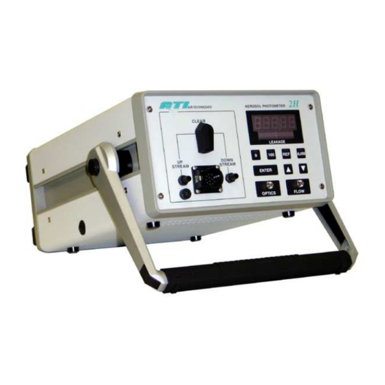
2H and 2H-N
Aerosol Photometers
Air Techniques International
Division of Hamilton Associates, Inc
11403 Cronridge Drive
Owings Mills, MD 21117 USA
TEL: 410 363-9696
FAX: 410 363-9695
www.atitest.com
info@atitest.com
IQ/OQ 2H, 2H-N
Revision 0
Advertisement
Table of Contents

Subscribe to Our Youtube Channel
Related Manuals for ATI Technologies 2H


Summary of Contents for ATI Technologies 2H
- Page 1 IQ/OQ Installation / Operation Qualification MANUAL for the 2H and 2H-N Aerosol Photometers Air Techniques International Division of Hamilton Associates, Inc 11403 Cronridge Drive Owings Mills, MD 21117 USA TEL: 410 363-9696 FAX: 410 363-9695 www.atitest.com info@atitest.com IQ/OQ 2H, 2H-N...
- Page 2 This page intentionally left blank Revision A...
-
Page 3: Table Of Contents
Changing Setup Parameters Setting Up the Alarm Functions Changing the Reference UPSTREAM AEROSOL Measurements (DOP or PAO) Measuring % Leakage - User Defined Reference (USER) Testing with the 2H Verifying the Upsream Concentration During Test MAINTENANCE Weekly Annually General Maintenance procedures... - Page 4 Replacing the HEPA Exhaust Filter A-1. SPECIFICATIONS A-2. TROUBLESHOOTING A-3. QUICK SETUP REFERENCE A-4. RS-232 COMMUNICATION Revision A...
- Page 5 Guidelines to the use of this manual SYMBOLS The following symbols are used throughout the manual to draw attention to items or procedures that require special notice or care. Operator required action. Note: Contains important information that, if ignored, can cause inaccurate readings. Caution: Contains information that, if ignored, can cause equipment damage.
-
Page 6: Installation Qualification
If the instrument has been damaged in transit, notify the shipper immediately. Make sure the following items are included with both the 2H (9300133) and the 2HHP (9300134): 1) 1 power cord, 6700001 (120 VAC) or T2E0-0063 (220 VAC) -
Page 7: Setup
4. Scanning Probe Connector. Electrical connection for the optional Scanning Probe. NOTE: Connect the Scanning Probe before applying power to the 2H. Failure to do so will result in the lack of operation of Scanning Probe’s display. If this occurs, simply turn off the power to the unit and restart the system. -
Page 8: Front Panel Controls And Indicators
The Selector Valve, the Scanning Probe connector, and the two barbed fittings are discussed later. SCANNING PROBE CONNECTIONS If using the 2H with the Scanning Probe, connect the probe’s electrical connector to the 12-pin connector on the front panel of the 2H before applying power to the photometer. Otherwise, the display on the Scanning Probe will not function. -
Page 9: Rear Panel Connections
Note: When using the TDA-2SP Scanning Probe with the 2H, the probe must be connected to the photometer before the power is turned on. Otherwise the 2H will not detect the probe and no display will be observed on the pistol grip. If this occurs, switch... -
Page 10: Side Connection
CAUTION: The 2H should always be positioned so that the Power Switch, located on the rear panel, is readily accessible in the event the unit needs to be powered off quickly. The Power Connector accepts the female end of the Power Cord that comes with the unit. The internal power supply is a universal supply that can operate at either 50 or 60 Hz and with any voltage from 90 to 240 volts, for use in virtually all countries. -
Page 11: Operational Qualification
If the Scanning Probe is being used, connect it to the Scanning Probe Connector and the Downstream Port. Verify that the Selector Valve is in the CLEAR position. Apply power to the 2H by setting the Power Switch to the 1 (On) position. The following events will occur: 1. The display will show “8.8.8.8.8.”... -
Page 12: Changing Setup Parameters
Parameter Description Valid Range Default Value Audible Alarm ON / OFF 0% Sample Time 5 - 120 seconds 10 seconds 100% Sample Time 5 - 120 seconds 10 seconds Decimal Places 3 - 4 Internal Reference Hour Meter Load Factory Defaults Software Revision Bar Graph Display ON / OFF... - Page 13 Options: Default: Enables or disables the audible portion of the 2H alarms. The unit parameter is factory set to off. When L1 is displayed in the parameter menu, press the <ENTER> function key to access the stored setting. Press the <Δ> (Up) and <∇> (Down) function keys to change the displayed setting between ON and OFF.
- Page 14 L4 – Decimal Places to be displayed Options: 3 or 4 Default: This parameter is used to select either 3 or 4 decimal places on the % Leakage Display. When [L4] is displayed in the parameter menu, press the <ENTER> function key to access the stored setting.
- Page 15 Press <ENTER> to set the selection and return to the parameter select menu. [L7] will be displayed. L8 – Software Revision Options: Default: [L8] displays the current revision that is being used by the 2H main firmware. L9 – Bargraph Display Options: OFF - Disabled ON - Enabled...
- Page 16 Press <ENTER> to set the selection and return to the parameter select menu. [L9] will be displayed. L10 – % Leakage Display Intensity Options: Default: [L10] is used to adjust the intensity of the green LED display in the % Leakage display. When [L10] is displayed in the parameter menu, press the <ENTER>...
-
Page 17: Setting Up The Alarm Functions
120 seconds. Press <ENTER> when done. [L12] will be displayed. SETTING UP THE ALARM FUNCTIONS The 2H has an alarm feature which can alert the user when particle concentration exceeds a user- selected % Leakage value. To set the alarm features, perform the following steps: 1. -
Page 18: Upstream Aerosol Measurements (Dop Or Pao)
UPSTREAM AEROSOL MEASUREMENTS (DOP OR PAO) Note: Do not perform the steps in this section until completing section 3.1, Initialization. Note: If there is a concern that the zero baselines may have drifted, the operator may re- zero the instrument at any time by positioning the selector valve to the clear position, pressing the <0>... -
Page 19: Testing With The 2H
<DOWNSTREAM>. The % LEAKAGE display indicates the concentration as compared to the upstream value. TESTING WITH THE 2H After the 100% and 0% baselines have been established, the unit is ready for testing operations. During testing operations, readings may be taken from either the Front Panel Display or the Scanning Probe, lessening operator distraction. -
Page 20: Maintenance
% LEAKAGE display. RECOMMENDED SPARE PARTS Spare components are not supplied with the 2H or the 2H-N nuclear unit and must be ordered separately. See section A-4 for a list of recommended spare parts that may be purchased in kit form or individually. -
Page 21: Cleaning The Tda-2Sp Scanning Probe Screens
REPLACING THE MAIN POWER FUSES Position the 2H with the rear panel readily accessible. Locate the fuse block at the center of the power entry connector. Press the top and bottom tabs toward the center and pull the fuse block straight out from the power entry connector. -
Page 22: A-1. Specifications
13.5 in x 9.5 in x 5.0 in 34.3 cm x 24.0 cm x 12.7 cm Weight Aerosol Photometer (standard use) 15.5 lbs (7.0 kg) 2H-N Aerosol Photometer (nuclear use) 15.5 lbs (7.0 kg) TDA-2SP Scanning Probe 2.5 lbs (1.1 kg) Input Power 90 to 250 volts AC, 50 or 60 Hz, 1.5 amps... -
Page 23: A-2. Troubleshooting
A-2. TROUBLESHOOTING CONTROLLER Error Messages ERROR CODES – SYSTEM PROBLEMS Problems Cause Corrective Action The unit has not been calibrated Return the unit to ATI or E1 – Calibration flags not or the unit has lost memory. Authorized service center for repair and service as soon as possible. -
Page 24: A-3. Quick Setup Reference
A-3. QUICK SETUP REFERENCE SETUP Δ To enter setup, press < > then <ENTER> Δ ∇ Δ ∇ Press < > or < > then <ENTER> to select function, then < > or < > to change Audible Alarm (On/Off) 0 Sample Time (5 to 120 seconds) 100% Sample Time (5 to 120 seconds) Decimal Places (3 or 4) - Page 25 *USER is a stored sampled concentration saved by the user, to be displayed as 100%. This value is stored in memory until a new value is sampled and saved by the user. To set: After completing the setting 100% procedure below, Press the REF button and “USER” will be displayed.
-
Page 26: A-4. Rs-232 Communication
A-4. RS-232 COMMUNICATION The 2H serial output is formatted as a continuous string of ASCII numeric characters. The recommended method for capturing this data is to use the DAS1 or DAS2 data acquisition system from ATI. Shown below are screenshots from the DAS1 on a pocket PC. Contact ATI customer service for details and other information. - Page 27 This page intentionally left blank. Revision A...
Need help?
Do you have a question about the 2H and is the answer not in the manual?
Questions and answers