Table of Contents
Advertisement
Quick Links
Advertisement
Table of Contents

Related Manuals for OHAUS T71P


Summary of Contents for OHAUS T71P
- Page 1 7000 Series Indicators Instruction Manual T71P T71XW...
-
Page 3: Table Of Contents
Internal Connections ............................12 2.3.1 Opening the Housing........................12 2.3.2 Scale Base without Connector to T71P or T71XW ................12 2.3.3 RS232 Interface Cable to T71XW....................... 13 2.3.4 Footswitch to T 71P or T71XW ......................13 2.3.5... - Page 4 EN-2 7000 Series Ind icators 3.5.4 Filter ............................... 25 3.5.5 Auto Zero Tracking ........................... 25 3.5.6 Backlight............................25 3.5.7 Auto Off Timer..........................26 3.5.8 Gross Indicator ..........................26 3.5.9 End Readout............................ 26 Mode Menu..............................
- Page 5 7000 Series Indicators EN-3 3.12.5 Lock Mode ............................40 3.12.6 Lock Unit............................40 3.12.7 Lock Print1............................41 3.12.8 Lock Print2............................41 3.12.9 Lock COM1 ............................. 41 3.12.10 Lock COM2 ............................. 41 3.12.11 Lock GMP ............................
- Page 6 EN-4 7000 Series Ind icators 7. MAINTENANCE................................ 62 Cleaning ............................... 62 Troubleshooting............................. 62 Service Information ............................63 8. TECHNICAL DATA ..............................64 Specifications ..............................64 Accessories and Options ..........................65 Drawings and Dimensions..........................
-
Page 7: Introduct Ion
7000 Series Indicators EN-5 INTRODUCTION Safety Precautions CAUTION: READ ALL SAFETY WARNINGS BEFORE INSTALLING, MAKING CONNECTIONS, OR SERVICING THIS EQUIPMENT. FAILURE TO COMPLY WITH THESE WARNINGS COULD RESULT IN PERSONAL INJURY AND/OR PROPERTY DAMAGE. RETAIN ALL INSTRUCTIONS FOR FUTURE REFERENCE. €... -
Page 8: Overview Of Pa Rts And Controls
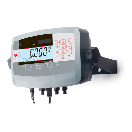
RS232 connector Cable gland for Scale 2 load cell cable or option cable Load cell connector for Scale 1 Cable gland for Scale 1 load cell cable Hole plug for option Power receptacle 15 14 13 Figure 1-1. T71P Indicator... - Page 9 7000 Series Indicators EN-7 Item Description Data label (on top) Front housing Control Panel Adjusting knob (2) Mounting bracket Bolt (4) Rear housing Data label Location for security screw Power cord Cable gland for Scale 1 load cell cable Cable gland for Scale 2 load cell cable Cable gland for RS232 option, RS485/RS422...
- Page 10 DC power connection Scale 2 sense jumper W3 Alibi option connection Scale 1 sense jumper W2 Option connection Scale 1 load cell connector J14 (T71P only) Battery connection (T71P only) Scale 1 load cell terminal block J4 Figure 1-3. Main PC Board...
- Page 11 7000 Series Indicators EN-9 Item Description Item Description Display window LIBRARY Edit button UNDER LED TARE Menu Exit button ACCEPT LED FUNCTION Mode Back button OVER LED PRINT Units No button Capacity label window ON/ZERO Off Yes button Keypad Figure 1-4. Control Panel 12 11 10 Item Description Item...
-
Page 12: Control Functions
EN-10 7000 Series In dicators Control Functions Button Primary Function ON/ZERO PRINT FUNCTION TARE LIBRARY (Short Press) Turn the indicator Send the displayed Initiate the function Perform a tare Display the library value to the COM of the current operation. data. -
Page 13: Installation
2.2.1 Scale Base with Connector to T71P Ohaus bases with a circular connector can be attached to the external load cell connector (Figure 1-1, item 13). Refer to Section 2.3.2 for bases without a connector. To make the connection, plug the base’s connector onto the external load cell connector, and then rotate the locking ring clockwise. -
Page 14: Mounting Bracket Attachment
2.3.2 Scale Base without Connector to T71P or T71XW Bases without a circular connector must be attached to one of the internal load cell connectors on the main pc board. Pass the load cell cable through a cable gland (Figure 1-1, item 14 or Figure 1-2, item 11 or 12) and attach it to terminal block J4 (Figure 1-3, item 9) or terminal block J7 (Figure 1-3, item 5). -
Page 15: Rs232 Interface Cable To T71Xw
T71P Housing Orientation The T71P is delivered in the wall mount orientation, with connections exiting below the display. The rear housing may be reversed so the connections exit above the display. This orientation is convenient when the T71P is placed horizontally on a bench. -
Page 16: Settings
EN-14 7000 Series Indicators SETTINGS Menu Structure CALIBRATION SETUP READOUT MODE UNIT PRINT1 • ZERO1 • RESET • RESET • RESET • RESET • RESET • RESET • ZERO2 • NO • NO • NO • NO • NO • NO •... - Page 17 7000 Series Indicators EN-15 PRINT2 COM1 COM2 LOCK MENU LOCK KEY • RESET • RESET • RESET • RESET • RESET • RESET • NO • NO • NO • NO • NO • NO • YES • YES • YES •...
-
Page 18: Menu Navigation
EN-16 7000 Series Indicators Menu Navigation The following method is used to navigate the menu and change the settings. Enter the menu by pressing and holding the Menu button until MENU is displayed. • Press the No button to move to the next menu or press the Back button to move to the previous menu. •... -
Page 19: Calibration Menu
7000 Series Indicators EN-17 Calibration Menu mMENU When CALIBRATION is displayed, press the Yes button to accept the Calibration menu. Press the No CALIBRATION button to advance to the desired menu item. NOTES: Before entering the Zero, Span, 3 Point Linearity or 5 Point Linearity menu items, remove all load from the scale. -
Page 20: Point Linearity Calibration
EN-18 7000 Series Indicators 3.3.3 3 Point Linearity Calibration Use this calibration method to adjust the zero calibration point, 1/2 and full load calibration points. 3 PT LINEAR With no load on the scale, press the Yes button. The display shows the current full load calibration 3LIN point and calibration unit of measure. -
Page 21: Calibration Test
7000 Series Indicators EN-19 Place the specified 3/4 load calibration weight on the scale and press the Yes button. The display 5LIN shows --C--, followed by the 1/2 load calibration point. --C-- 5LIN Place the specified 1/2 load calibration weight on the scale and press the Yes button. The display 5LIN shows --C--, followed by the 1/4 load calibration point. -
Page 22: Geographical Adjustment Factor
EN-20 7000 Series Indicators 3.3.6 Geographical Adjustment Factor Geographical Adjustment Factor (GEO) is used to adjust the calibration based on the current location. Refer to Section 6, table 6-1 and set the GEO factor that corresponds to your location. Settings from 1 to 31 are available. Press the No or Back button to change the value. -
Page 23: Range2
7000 Series Indicators EN-21 3.4.4 Range2 SEtUP Set the number of weighing ranges for Scale 2. RANGE2 SINGLE = one weighing range from zero to capacity. rANGE2 DUAL = two weighing ranges. The fine range (1r) is from zero to half SINGLE capacity. -
Page 24: Graduation2
EN-22 7000 Series Indicators 3.4.8 Graduation2 SEtUP Set the readability of Scale 2. GRADUATION2 Settings of 0.0001, 0.0002, 0.0005, 0.001, 0.002, 0.005, 0.01, 0.02, 0.05, 0.1, 0.2, Grad2 0.5, 1, 2, 5, 10, 20, 50, and 100 are available. 0.0001 NOTE: Graduation2 setting selections are dependent on the Capacity2 setting. -
Page 25: Accumulate
7000 Series Indicators EN-23 3.4.12 Accumulate SEtUP Set the accumulate functionality. ACCUMULATE = accumulation is disabled. ACCUmM MANUAL = the displayed value is manually added to the total by pressing the FUNCTION button. AUTO = the displayed value is automatically added to the total when the MANUAL display becomes stable. -
Page 26: Key Beep
EN-24 7000 Series Indicators 3.4.17 Key Beep SEtUP Set whether the beeper sounds when a button is pressed. KEY BEEP = no sound KEY.BP = sound 3.4.18 Library SEtUP Set whether the library memory is enabled. LIBRARY = Data cannot be stored in the library memory. = data can be stored in the library memory. -
Page 27: 7000 Series Indicators
7000 Series Indicators EN-25 3.5.3 Stable Range rEAd Set the amount the reading can vary while the stability symbol remains on. STABLE RANGE 0.5 d = 0.5 graduations StAbLE = 1 graduation = 2 graduations 0.5 D = 3 graduations = 5 graduations NOTE: When LEGAL FOR TRADE is set to ON, the setting is forced to 1 d. -
Page 28: End Readout
EN-26 7000 Series Indicators 3.5.7 Auto Off Timer rEAd Set the automatic shut off functionality. AUTO OFF = disabled. A.OFF 1 MINUTE = the indicator turns off after 1 minute of inactivity. 2 MINUTES = the indicator turns off after 2 minutes of inactivity. 5 MINUTES = the indicator turns off after 5 minutes of inactivity. -
Page 29: Parts Counting Optimization
7000 Series Indicators EN-27 3.6.4 Parts Counting Optimization COUNt When the Parts Counting mode is turned ON, Parts Counting Optimization can be used to PC AUTO OPT automatically adjust the average piece weight (APW). Each time a quantity greater than 1x or less then 3x the previous quantity is placed on the scale, the APW is adjusted. -
Page 30: Unit Menu
EN-28 7000 Series Indicators Unit Menu mMENU Enter this menu to activate the desired units of measure. UNIT NOTE: Due to national laws, the indicator may not include some of the units of measure listed. 3.7.1 Reset UNIt Reset the Unit menu to the factory defaults. Factory default settings are shown in bold. RESET = not reset rESEt... -
Page 31: Tonne Unit
7000 Series Indicators EN-29 3.7.7 Tonne Unit UNIt Set the status. TONNE = disabled UNIt = enabled NOTE: Tonne Unit is not available when Range is set to DUAL or when Graduation setting is less than 0.01 kilograms or 0.02 pounds. 3.7.8 Custom Unit Use Custom Unit to display weight in an alternative unit of measure. -
Page 32: Gmp Menu
EN-30 7000 Series Indicators GMP Menu mMENU Enter this menu to set the Good Manufacturing Practices data. 3.8.1 Reset GmMP Reset the GMP menu to the factory defaults. Factory default settings are shown in bold. RESET = not reset rESEt = reset 3.8.2 Date... -
Page 33: User Id
7000 Series Indicators EN-31 3.8.4 User ID GmMP Set the user identification. USER ID Alphanumeric settings up to 12 characters are available. The default setting is 000000. USEr.ID 000000 xxxxxxxxxxxx 3.8.5 Project ID GmMP Set the project identification. PROJECT ID Alphanumeric settings up to 12 characters are available. -
Page 34: Auto Print
EN-32 7000 Series Indicators 3.9.3 Auto Print PrINt1 Set the automatic printing functionality. AUTO PRINT = disabled A.PrINt ON STABLE = printing occurs each time the stability criteria are met. INTERVAL = printing occurs at the defined time interval. ACCEPT = in Checkweigh mode, printing occurs each time the display is within ON STABLE the accept range and the stability criteria are met. - Page 35 7000 Series Indicators EN-33 Tare CONtNt Set the status. TARE = the tare weight is not printed. tArE = the tare weight is printed. 2.000 kg T Header CONtNt Set the status. HEADER = the user defined header is not printed. HEAdEr = the user defined header is printed.
- Page 36 EN-34 7000 Series Indicators Difference CONtNt Set the status. DIFFERENCE = the difference is not printed following the Calibration Test procedure. dIFF = the difference is printed following the Calibration Test procedure. --------- Cal Test --------- New Cal: 10.000 kg Old Cal: 9.999 kg Diff: 0.001 kg Wt.
-
Page 37: Layout Sub-Menu
7000 Series Indicators EN-35 Mode CONtNt Set the status. MODE = the current mode is not printed. mMOdE = the current mode is printed. Mode: XXXXXX Name CONtNt Set the status. NAME = the name line is not printed. NAmME = the name line is printed. -
Page 38: List
EN-36 7000 Series Indicators 3.9.6 List PrINt1 Print the specified data. LIST = do not print. LISt = print the menu settings. 3.9.7 End Print1, End Print2 PrINt1 Advance to the next menu or return to the top of the current menu. END PRINT1 3.10 COM1, COM2 Menus... -
Page 39: Stop Bit
7000 Series Indicators EN-37 3.10.4 Stop Bit COmM 1 Set the number of stop bits. STOP BITS = 1 stop bit StOP = 2 stop bits 3.10.5 Handshake COmM 1 Set the flow control method. HANDSHAKE NONE = no handshaking HANdSH XON-XOFF = XON/XOFF handshaking... -
Page 40: End Com1, End Com2
EN-38 7000 Series Indicators Alternate Zero Command ALt.CmM Set the alternate command character for Zero. ZERO Settings of A to Z are available. The default setting is Z. ZErO 3.10.8 End COM1, End COM2 COmM1 Advance to the next menu or return to the top of the current menu. END COM1 3.11 I-O Menu... -
Page 41: Relay Output Sub-Menu
7000 Series Indicators EN-39 3.11.4 Relay Output Sub-menu Set the relay output parameters. OUTPUT NOTE: The Relay Output sub-menu and associated menu items are not displayed unless the optional Relay PC Board is installed. Type OUtPUt Set the initial state of the relay. TYPE OPEN = the relay output is normally open. -
Page 42: Menu Lock Menu
EN-40 7000 Series Indicators 3.12 Menu Lock Menu mMENU Use this menu to prevent unauthorized changes to menu settings. When the security switch is set to MENU LOCK ON, the locked menus can be viewed but not changed. 3.12.1 Reset L.mMENU Reset the Menu Lock menu to the factory defaults. -
Page 43: Lock Print1
7000 Series Indicators EN-41 3.12.7 Lock Print1 L.mMENU Set the status. LOCK PRINT1 = the Print1 menu is not locked. L.Prt1 = the Print1 menu is locked. 3.12.8 Lock Print2 L.mMENU Set the status. LOCK PRINT2 = the Print2 menu is not locked. L.Prt2 = the Print2 menu is locked. -
Page 44: Key Lock Menu
EN-42 7000 Series Indicators 3.13 Key Lock Menu mMENU Use this menu to prevent unauthorized access to button functions. When the security switch is set to KEY LOCK ON, the locked buttons are disabled. 3.13.1 Reset L.key Reset the Key Lock menu to the factory defaults. Factory default settings are shown in bold. RESET = not reset rESEt... -
Page 45: Lock Function Button
7000 Series Indicators EN-43 3.13.7 Lock Function Button L.key Set the status. LOCK FUNC = the FUNCTION button is not locked. L.FUNC = the FUNCTION button is locked. 3.13.8 Lock Mode Button L.key Set the status. LOCK MODE = the Mode button is not locked. L.mMOdE = the Mode button is locked. -
Page 46: End Menu
Open the housing as explained in Section 2.3.1. Set the position of the switch to ON as shown in Section 1.2, Figure 1-3, Item When the switch is in the ON position, the start up display includes the LOCK ON message. OHAUS LOCK ON Note: This switch is also used in conjunction with the Legal for Trade menu item. -
Page 47: Operation
7000 Series Indicators EN-45 OPERATION Turning Indicator On/Off To turn the indicator on, press the ON/ZERO Off button. The indicator performs a display test 0.000 followed by a series of informational displays, and then enters the last active mode. To turn the indicator off, press and hold the ON/ZERO Off button until -OFF- is displayed. -Off- If powered by AC mains, the indicator enters standby and displays the clock. -
Page 48: Printing Data
EN-46 7000 Series Indicators Printing Data Press the PRINT button to send data to a printer or computer. NOTE: To ensure that the desired data is output correctly, first set the printing parameters (Section 3.9) and the Communication parameters (Section 3.10). NOTE: Data may also be printed using the P command. - Page 49 7000 Series Indicators EN-47 NOTE: To change the specified number of pieces, repeatedly press the No button. The display will 0.000 step through the alternative sample sizes: PLACE 5, PLACE 10, PLACE 20, PLACE 50 and PLACE PLACE 20 OR 100.
-
Page 50: Percent Weighing
EN-48 7000 Series Indicators 4.9.3 Percent Weighing mMOdE Use this mode to compare the weight of items as a percentage of a Reference Weight. PERCENT Defining the Reference Weight PErCNt When the Mode button is released, CLEAR REF? is displayed. Press the No button to use the stored CLEAR REF? Reference Weight or press the Yes button to establish a new Reference Weight. -
Page 51: Check Weighing
7000 Series Indicators EN-49 4.9.5 Check Weighing mMOdE Use this mode to compare the weight or quantity of items to a target weight range. The indicator CHECKWEIGH supports positive, negative and zero check weighing. NOTES: Press the FUNCTION button to briefly display the limits if Accumulate is set to OFF in the Setup menu. -
Page 52: Library
EN-50 7000 Series Indicators Zero Check Weighing -1.000 Zero check weighing is used when comparing subsequent samples to an initial reference sample. In this case, the under limit must be a negative value and the over limit must be a positive value. ○... - Page 53 7000 Series Indicators EN-51 Weighing Mode Library Records The Name of the item is displayed. By default, the Name is the same as the Record ID. Use the NAmME keypad to change the value. Press the Yes button to accept the value. W001 NAmME APPLES...
- Page 54 EN-52 7000 Series Indicators The Preset Tare of the item is displayed. By default, the current Tare is used as the Preset Tare P.tArE value. Use the keypad to change the value. Press the Yes button to accept the value. 0.000 KG P.tArE 1.000 KG...
-
Page 55: Retrieving Data
7000 Series Indicators EN-53 Dynamic Weighing Mode Library Records The Name of the item is displayed. By default, the Name is the same as the Record ID. Use the NAmME keypad to change the value. Press the Yes button to accept the value. D001 NAmME CATTLE... -
Page 56: Accumulation And Statistics
EN-54 7000 Series Indicators If desired, edit the displayed data value using the keypad. Then press the Yes button. P.tArE 0.000 KG P.tArE 1.000 KG After all data types have been viewed, press the Yes button to save the changes. PC003 SAVE RECORD? 4.11... -
Page 57: Alibi Memory
7000 Series Indicators EN-55 4.12 Alibi Memory When the optional Alibi Memory pc board is installed, weighing results may be stored in memory for future reference by pressing the PRINT button or sending the “P” command. Up to 262,112 alibi records may be stored. The following data is stored for each mode. -
Page 58: Serial Communication
EN-56 7000 Series Indicators SERIAL COMMUNICATION Interface Commands The indicator can be controlled using the commands listed below. Command Function Characters Turns the indicator on. Turns the indicator off. Immediate print of displayed weight (stable or unstable). Print displayed weight (stable or unstable). Print on stability. -
Page 59: Printout Examples
Examples for modes are shown with all CONTENT settings ON and values defined for the header lines. Content Weigh Mode Count Mode Percent Mode HEADER 1 Ohaus Corporation Ohaus Corporation Ohaus Corporation HEADER 2 19A Chapin Road 19A Chapin Road... - Page 60 New Cal: 10.000 kg Old Cal: 10.000 kg Diff: 0.000 kg Wt. ID: ------------------ ------------ End ----------- HEADER 1 Ohaus Corporation HEADER 2 19A Chapin Road HEADER 3 Pine Brook, NJ, 07058 HEADER 4 HEADER 5 Tel: +1-973-377-9000 TIME 01/31/08...
-
Page 61: Legal For Trade
For jurisdictions that use the physical sealing method, the local weights and measures official or authorized service agent must apply a security seal to prevent tampering with the settings. Refer to the illustrations below for sealing methods. Figure 6-1. T71P Wire Seal Figure 6-2. T71P Paper Seal Figure 6-4. -
Page 62: Audit Trail Seal
When the scale base is attached to the indicator using a connector, it is necessary to seal the load cell cable to the indicator in some jurisdictions. The load cell sealing collar P/N 80500737 (Figure 6-5) is available as an accessory. Figure 6-5. T71P Load Cell Sealing Collar 6.3.2... - Page 63 7000 Series Indicators EN-61 TABLE 6-1. GEOGRAPHICAL ADJUSTMENT VALUES Elevation in meters 1300 1625 1950 2275 2600 2925 3250 1300 1625 1950 2275 2600 2925 3250 3575 Elevation in feet 1060 2130 3200 4260 5330 6400 7460 8530 9600 10660 1060 2130 3200...
-
Page 64: 7000 Series Indicators
Check power cord connections. Make sure power connected. cord is plugged into the power outlet. Power outlet not supplying electricity. Check power source. Battery discharged (T71P). Replace batteries (T71P). Other failure. Service required. Cannot zero the display or Load on scale exceeds allowable limits. -
Page 65: Service Information
United States, call toll-free 1-800-526-0659 between 8:00 AM and 5:00 PM Eastern Standard Time. An Ohaus Product Service Specialist will be available to assist you. Outside the USA, pleas visit our website www.ohaus.com to locate the Ohaus office nearest you. -
Page 66: Technical Data
Temperature: -10°C to 40°C / 14°F to104°F Relative humidity: Maximum relative humidity 80% for temperatures up to 31°C decreasing linearly to 50% relative humidity at 40°C. Altitude: up to 2000m TABLE 8-1. SPECIFICATIONS Indicator Model T71P T71XW Maximum displayed resolution 1:50,000 Maximum approved resolution 1:10,000... -
Page 67: Accessories And Options
Interface Cable, Printer CBM910, T71XW 80252574 Interface Cable, Printer STP103, T71P 80252581 Interface Cable, Printer STP103, T71XW 80252584 Interface Cable, PC 25 pin, T71P 80500524 Interface Cable, PC 9 pin, T71P 80500525 Interface Cable, PC 9 pin, T71XW 80500552 Interface Cable, PC 25 pin, T71XW... -
Page 68: Drawings And Dimensions
EN-66 7000 Series Indicators Drawings and Dimensions Figure 8-1. T71P Dimensions Figure 8-2. T71XW Dimensions... -
Page 69: Compliance
ISO 9001 Registration In 1994, Ohaus Corporation, USA, was awarded a certificate of registration to ISO 9001 by Bureau Veritus Quality International (BVQI), confirming that the Ohaus quality management system is compliant with the ISO 9001 standard’s requirements. On May 15, 2003, Ohaus Corporation, USA, was re-registered to the ISO 9001:2000 standard. - Page 70 Should this device be passed on to other parties (for private or professional use), the content of this regulation must also be related. Thank you for your contribution to environmental protection. For disposal instructions in Europe, refer to www.ohaus.com/weee.
-
Page 71: Series Indicators En
Ohaus. In lieu of a properly returned warranty registration card, the warranty period shall begin on the date of shipment to the authorized dealer. - Page 72 Ohaus Corporation 19A Chapin Road P.O. Box 2033 Pine Brook, NJ 07058-2033, USA Tel: (973) 377-9000 Fax: (973) 944-7177 With offices worldwide. www.ohaus.com *80251405* P/N 80251405 ©2008 Ohaus Corporation, all rights reserved. Printed in China...
Need help?
Do you have a question about the T71P and is the answer not in the manual?
Questions and answers