OHAUS T32ME Service Manual
Hide thumbs
Also See for T32ME:
- Instruction manual (240 pages) ,
- User manual (41 pages) ,
- Instruction manual (48 pages)

Related Manuals for OHAUS T32ME


Summary of Contents for OHAUS T32ME
- Page 1 SERVICE MANUAL 3000 Series T32ME & T32MC Indicators T32ME T32MC Ohaus Corporation 7 Campus Drive, Suite 310, Parsippany, NJ 07054 (973) 377-9000...
- Page 3 T32 Indicators: T32ME & T32MC The information contained in this manual is believed to be accurate at the time of publication, but Ohaus Corporation assumes no liability arising from the use or misuse of this material. Reproduction of this material is strictly prohibited.
-
Page 5: Table Of Contents
Power Test.........................4-1 Performance Tests Using a Scale Base ..............4-1 4.3.1 Overload/Underload Test ...................4-2 Performance Tests Using a Load Cell Simulator............4-2 Calibration Retention Test ..................4-2 RS232 Interface Test/Print Test ................4.2 3000 Series T32ME & MC Indicators Service Manual Ohaus Corporation www.ohaus.com... - Page 6 CHAPTER 5 PARTS LISTS & DIAGRAMS Page No. 3000 Series T32MC (LCD) Indicator: Housing & Internal Parts ........5-2 3000 Series T32ME (LED) Indicator: Housing & Internal Parts.........5-4 APPENDIX A SETUP & CALIBRATION VALUES Preliminary Steps ....................A-1 Span Calibration....................A-2 Linearity Calibration...................
-
Page 7: Figure No
TABLE OF CONTENTS FIGURE NO. TITLE Page No. 3-11 Main PCB ......................3-6 Series 3000 T32MC Indicator: Housing & Internal Parts........5-2 Series 3000 T32ME Indicator: Housing & Internal Parts........5-4 3000 Series T32ME & MC Indicators Service Manual Ohaus Corporation www.ohaus.com... - Page 8 TABLE OF CONTENTS Ohaus Corporation www.ohaus.com 3000 Series T32ME & MC Indicators Service Manual...
-
Page 9: Chapter 1 Getting Started
INTRODUCTION This service manual contains the information needed to perform routine maintenance and service on the Ohaus T32ME and T32MC Indicators. The contents of this manual are contained in five chapters: Chapter 1 Getting Started – Contains information regarding service facilities, tools and test equipment, specifications, hardware setup, operating the Indicator, and configuring the Indicator’s communication and Legal-for-Trade menus. -
Page 10: Tools And Test Equipment Required
1. Standard Electronics Tool Kit 2. Digital Voltmeter (DVM), with clip on probes. Input impedance of at least 10 megohms in the 1 Volt dc position. 3. Soldering Iron, solder and flux remover. Ohaus Corporation www.ohaus.com 3000 T32ME & MC Indicator Service Manual... -
Page 11: Specifications
Net Weight (lb/kg) 1.5 / 0.7 Shipping Weight (lb/kg) 4.0 / 1.8 Operating Temperature Range –10°C to 40°C / /14°F to 104°F Power 9 – 12 VDC, 0.5A, AC Adapter 3000 Series T32ME & MC Indicator Service Manual Ohaus Corporation www.ohaus.com... -
Page 12: Printed Circuit Board (Pcb), T32 Indicator
CHAPTER 1 HARDWARE SETUP Both the T32ME and T32MC connect to a scale base through a Load Cell Cable that connects to the Indicator’s Main Printed Circuit Board (PCB). When supplied as part of a scale, each model has a mounting bracket that attaches to the column bracket of the base scale. To remove the mounting bracket, remove the threaded knobs, holding the Indicator by hand. -
Page 13: Jumper Connections
Each model has a standard 9-pin D-style RS232 connector, with a pin configuration as illustrated in Figure 1-7. RS232 connector Figure 1-5. Bottom of Housing. Connection 6-9 N/C Figure 1-6. RS232 Pins. To adjust RS232 settings, see Section 1.8, page 1-8. 3000 Series T32ME & MC Indicator Service Manual Ohaus Corporation www.ohaus.com... -
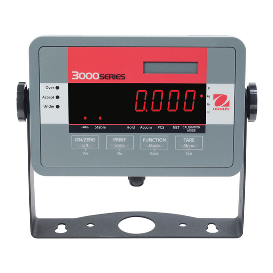
Page 14: Overview Of The Controls
Ounces, Kilograms, Grams Figure 1-7. T32MC (LCD) Display. Figure 1-8. T32ME (LED) Display. Indicators for Center of Zero, Hold, Accumulation Mode, (also Stable weight on T32ME) Counting (PCS) Mode, Net weight, & Calibration Mode. TABLE 1-2. FUNCTIONS OF DISPLAY CONTROLS... -
Page 15: Operation
Backs out of a list of selectable items to the previous middle level menu. – Exit Exits from menu directly to the active weighing mode. Table 1-3. T32 MENU STRUCTURE 3000 Series T32ME & MC Indicator Service Manual Ohaus Corporation www.ohaus.com... -
Page 16: Rs232 Interface Connection
Press No to advance, Back to regress, and Yes to accept a setting. After you press Yes, INtEr appears again. Press No twice, then Yes when End appears, No when P.r.i.n.t appears, No again, and Yes when End appears again to exit menu mode. Ohaus Corporation www.ohaus.com 3000 T32ME & MC Indicator Service Manual... -
Page 17: Interface Commands
Units, up to five characters. Stability, “?” character is printed if not stable, blank if stable. Legend, up to 3 characters: G = gross weight, NET = net weight, T = tare 3000 Series T32ME & MC Indicator Service Manual Ohaus Corporation www.ohaus.com... -
Page 18: Legal For Trade (Lft)
LFT mode again. The weights and measures official may apply a wire or paper security seal as shown below. Paper Seal Figure 1-9. T32 Wire Seal Figure 1-10. T32 Paper Seal Ohaus Corporation www.ohaus.com 1-10 3000 T32ME & MC Indicator Service Manual... -
Page 19: Chapter 2 Troubleshooting
See Chapter 3, Maintenance Procedures, for board replacement and testing. If the Indicator shows no sign of physical damage, continue with procedures. See chart below for visual checking procedures. Figure 2-1. Visual Checking Procedures. 3000 Series T32ME & MC Indicators Service Manual Ohaus Corporation www.ohaus.com... -
Page 20: Error Codes
You may continue to weigh, but results piece weight of the parts is small may not be accurate, because average (warning). piece weight is smaller than can be accurately counted. Ohaus Corporation www.ohaus.com 3000 Series T32ME & MC Indicators Service Manual... -
Page 21: Problem Solver
Lock switch on PCB is “on”. Set the Lock switch on PCB to Off. LFT menu set to On. Set LFT menu to Off. If problem continues, test/replace PCB. 3000 Series T32ME & MC Indicators Service Manual Ohaus Corporation www.ohaus.com... - Page 22 CHAPTER 2 TROUBLESHOOTING Ohaus Corporation www.ohaus.com 3000 Series T32ME & MC Indicators Service Manual...
-
Page 23: Preventive Maintenance
CHAPTER 3 REPAIR PROCEDURES PREVENTIVE MAINTENANCE Ohaus Indicators are precision instruments and should be carefully handled, stored in a clean, dry, dust-free area, and cleaned periodically. Follow these precautionary steps: – When an Indicator has had chemicals or liquids spilled on it, all exterior surfaces should be cleaned as soon as possible with warm water on a damp cloth. -
Page 24: Testing The Printed Circuit Board (Pcb)
Load Cell for the purposes of troubleshooting and calibration. The next section explains in detail how simulators work and what type of load cells they can “substitute for,” i.e., simulate. Ohaus Corporation www.ohaus.com 3000 Series T32ME & MC Indicators Service Manual... -
Page 25: How Strain Gauge Load Cells Operate
The gauges sense very small deflections in the metal caused by the load applied to the cell. Figure 3-7. Typical Strain Gauge Load Cell. Internal PCB 3000 Series T32ME & MC Indicators Service Manual Ohaus Corporation www.ohaus.com... -
Page 26: Downward Force On Load Cell Bends The Beam
Excitation wires. The Sense wires compensate for resistance in the cable and are often used if there is long distance between load cell and indicator. Ohaus Corporation www.ohaus.com 3000 Series T32ME & MC Indicators Service Manual... -
Page 27: How To Operate Simulators
The function of a Simulator is to simulate the output of a full bridge Load Cell, allowing the scale to be separated from the Load Cell for the purposes of troubleshooting and calibration. A typical Ohaus Load Cell is rated at 2mV/V output with a 5-Volt excitation voltage applied. (These values vary for specific models.) 3.3.2.4 How to Attach a Simulator... -
Page 28: Correcting Underload And Overload Errors
3. Upon completion of calibration, the PCB can be further checked using the Simulator to simulate various weight values. If simulator settings and weight readings on the scale agree, the PCB is functional. Ohaus Corporation www.ohaus.com 3000 Series T32ME & MC Indicators Service Manual... -
Page 29: Replacing The Printed Circuit Board (Pcb)
Disconnect the cables from any of the connectors (RS232, Load Cell, power jacks) for which the cable set is to be replaced. 3. Reconnect the wires to the PCB. 3000 Series T32ME & MC Indicators Service Manual Ohaus Corporation www.ohaus.com... -
Page 30: Function Label Replacement
Use a rolling motion to smooth it into position. 4. Close the Housing (if opened previously), re-insert and tighten the four screws previously removed. 5. Perform calibration procedures. (See Appendix A.) Perform testing procedures. (See Chapter 4.) Ohaus Corporation www.ohaus.com 3000 Series T32ME & MC Indicators Service Manual... -
Page 31: Chapter 4 Testing
2. Place a mass on the scale base platform which slightly exceeds the capacity of the scale base, and observe the Indicator display. The display should indicate Error 8.3. Remove the mass from the scale base. The display should return to zero. 3000 Series T32ME & MC Indicators Service Manual Ohaus Corporation www.ohaus.com... -
Page 32: Overload/Underload Test
Indicator’s print function. Press the Print/Units button. Printing to an external printer or computer should occur – each time the button is pressed. Ohaus Corporation www.ohaus.com 3000 Series T32ME & MC Indicators Service Manual... -
Page 33: Chapter 5 Parts Lists & Diagrams
In all cases where a part is replaced, the indicator must be thoroughly checked after the replacement is made. The indicator MUST meet the parameters of all applicable specifications in this manual. If further technical information is needed, please contact your local Ohaus office, or: Ohaus Corporation www.ohaus.com... -
Page 34: Series T32Mc (Lcd) Indicator: Housing & Internal Parts
CHAPTER 5 PARTS LISTS & DIAGRAMS 3000 SERIES T32MC (LCD) INDICATOR: HOUSING & INTERNAL PARTS Figure 5-1. Series 3000 T32MC Indicator: Housing & Internal Parts. Ohaus Corporation www.ohaus.com 3000 Series T32ME & MC Indicators Service Manual... -
Page 35: 3000 Series T32Mc (Lcd) Indicator: Housing & Internal Parts
Housing, Top LCD, W/backlight Main PCB Bottom Housing Knobs (set of 2) Wall Mount Kit Cable Set I/O Fitting, M12 Hardware Kit Adapter,Univ.,100-240V,10W Plug Set, AU/EU/GB/US Plug Set, EU/GB 3000 Series T32ME & MC Indicators Service Manual Ohaus Corporation www.ohaus.com... -
Page 36: Series 3000 T32Me Indicator: Housing & Internal Parts
CHAPTER 5 PARTS LISTS & DIAGRAMS 3000 SERIES T32ME INDICATOR: HOUSING & INTERNAL PARTS Figure 5-1. Series 3000 T32ME Indicator: Housing & Internal Parts. Ohaus Corporation www.ohaus.com 3000 Series T32ME & MC Indicators Service Manual... -
Page 37: 3000 Series T32Me (Led) Indicator: Housing & Internal Parts
CHAPTER 5 PARTS LISTS & DIAGRAMS 3000 SERIES T32ME (LED) INDICATOR: HOUSING & INTERNAL PARTS TABLE 5-2. T32ME (LED) INDICATOR: HOUSING & INTERNAL PARTS Drawing Item Description LFT Kit Function Label Housing, Top Main PCB Bottom Housing Knobs (set of 2) - Page 38 CHAPTER 5 PARTS LISTS & DIAGRAMS Ohaus Corporation www.ohaus.com 3000 Series T32ME & MC Indicators Service Manual...
-
Page 39: Preliminary Steps
5. Allow the Indicator to warm up for approximately five minutes after stabilizing to room temperature. 6. To abort calibration, press the Exit button anytime during the calibration process. 3000 Series T32ME & MC Indicators Service Manual A-1 Ohaus Corporation www.ohaus.com... -
Page 40: Span Calibration
The display shows --C-- while the full calibration point is established. After successful calibration, the scale exits to the active weighing mode and displays the actual weight value. Ohaus Corporation www.ohaus.com A-2 3000 Series T32ME & MC Indicators Service Manual... -
Page 41: Setup & Calibration Values
0.1, 0.2, 0.5, 1 0.5, 1 5, 10, 15, 20, 25, 30, 40, 50, 60, 75, 100, 120, 150, 200, 750, 1500 250, 300, 400, 500, 600, 750, 1000, 1200, 1500 3000 Series T32ME & MC Indicators Service Manual A-3 Ohaus Corporation www.ohaus.com... - Page 42 5, 10, 15, 20, 25, 30, 40, 50, 60, 75, 100, 120, 150, 200, 10000, 20000 250, 300, 400, 500, 600, 750, 1000, 1200, 1500, 2000, 2500, 3000, 5000, 6000, 7500, 10000, 2000 Ohaus Corporation www.ohaus.com A-4 3000 Series T32ME & MC Indicators Service Manual...
-
Page 43: Appendix Bgeographical Adjustment
25°21′ - 26°45′ 26°45′ - 28°06′ 28°06′ - 29°25′ 29°25′ - 30°41′ 30°41′ - 31°56′ 31°56′ - 33°09′ 33°09′ - 34°21′ 34°21′ - 35°31′ 35°31′ - 36°41′ 36°41′ - 37°50′ 3000 Series T32ME & MC Indicators Service Manual B-1 Ohaus Corporation www.ohaus.com... - Page 44 64°55′ - 66°24′ 66°24′ - 67°57′ 67°57′ - 69°35′ 69°35′ - 71°21′ 71°21′ - 73°16′ 73°16′ - 75°24′ 75°24′ - 77°52′ 77°52′ - 80°56′ 80°56′ - 85°45′ 85°45′ - 90°00′ Ohaus Corporation www.ohaus.com B-2 3000 Series T32ME & MC Indicators Service Manual...
- Page 46 *80253153* P/N 80253153 SERVICE MANUAL: 3000 SERIES T32MC & T32ME INDICATORS...
Need help?
Do you have a question about the T32ME and is the answer not in the manual?
Questions and answers