
Subscribe to Our Youtube Channel
Related Manuals for OHAUS T72XW AM


Summary of Contents for OHAUS T72XW AM
- Page 1 7000 Series Indicators Instruction Manual T72XW GlobalTestSupply www. .com Find Quality Products Online at: sales@GlobalTestSupply.com...
- Page 2 GlobalTestSupply www. .com Find Quality Products Online at: sales@GlobalTestSupply.com...
- Page 3 GlobalTestSupply www. .com Find Quality Products Online at: sales@GlobalTestSupply.com...
- Page 4 GlobalTestSupply www. .com Find Quality Products Online at: sales@GlobalTestSupply.com...
-
Page 5: Table Of Contents
TABLE OF CONTENTS INTRODUCTION ....................................1 ....................................1 ESCRIPTION ..................................... 1 EATURES ..................................... 1 PECIFICATIONS ..........................3 EFINITION OF IGNAL ARNINGS AND YMBOLS ................................... 3 AFETY RECAUTIONS ............................4 NSPECTION AND ONTENTS HECKLIST ................................... 4 HYSICAL IMENSIONS PCB ..................................... 5 .................................... - Page 6 3.5.1 Scale ....................................31 3.5.2 Application ..................................40 3.5.3 Indicator ..................................... 43 3.5.4 Communication ................................. 50 3.5.5 Maintenance ..................................54 APPLICATIONS: CONFIGURATION AND OPERATION ......................... 61 ..................................... 61 NTRODUCTION ................................61 NIMAL YNAMIC WEIGHING 4.2.1 Overview ................................... 61 4.2.2 Operational Features ................................. 61 4.2.3 Configuration ..................................
- Page 7 7000 SERIES INDICATORS EN 3 APPENDIX A DEFAULT TEMPLATES ............................... 102 APPENDIX B ALIBI MEMORY ................................104 APPENDIX C COMMUNICATIONS ............................... 107 APPENDIX D GEO CODES ................................... 134 GlobalTestSupply www. .com Find Quality Products Online at: sales@GlobalTestSupply.com...
- Page 8 GlobalTestSupply www. .com Find Quality Products Online at: sales@GlobalTestSupply.com...
-
Page 9: Introduction
7000 SERIES INDICATORS EN 1 INTRODUCTION Description The T72XW industrial scale indicator provides a compact yet flexible solution to a variety of weighing needs. Available as AC powered for stationary applications, this indicator is at home in virtually any industrial environment. Innovative use of Secure Data (SD) Memory technology expands the memory available for data storage when required. - Page 10 EN 2 7000 SERIES INDICATORS T72XW Specifications Power Operates at 85–264 VAC, 49–61 Hz and includes a power cord configured for the country of use. Power Consumption Table 1-2. Refer to Values shown are with internal COM2/DIO option and Ethernet option installed and load cell input loaded with 8 x 350...
-
Page 11: Definition Of Signal Warnings And Symbols
7000 SERIES INDICATORS EN 3 Table 1-3: T72XW Power Consumption Input Voltage I (mA) P (W) 5V/50 Hz 110 V/50 Hz 240 V/50 Hz 264 V/50 Hz 85 V/60 Hz 110 V/60 Hz 240 V/60 Hz 264 V/60 Hz Values shown are with internal Ethernet option installed and load cell input loaded with 8 x 350 load cells. Definition of Signal Warnings and Symbols Safety notes are marked with signal words and warning symbols. -
Page 12: Inspection And Contents Checklist
PROPERLY GROUNDED OUTLET ONLY. DO NOT REMOVE THE GROUND PRONG. DO NOT USE THE T72XW INDICATOR IN AREAS CLASSIFIED AS HAZARDOUS BECAUSE OF COMBUSTIBLE OR EXPLOSIVE ATMOSPHERES. CONTACT AN AUTHORIZED OHAUS REPRESENTATIVE FOR INFORMATION ABOUT HAZARDOUS AREA APPLICATIONS. WHEN THIS EQUIPMENT IS INCLUDED AS A COMPONENT PART... -
Page 13: Main Pcb
7000 SERIES INDICATORS EN 5 Main PCB The T72XW indicator’s main printed circuit board (PCB) provides the analog load cell scale interface, as well as the COM1 RS-232 serial port. The main board also contains the power input connection, display interface, keypad interface and six position DIP switch. -
Page 14: Sd Memory Option
EN 6 7000 SERIES INDICATORS 1.11.4 SD Memory Option An optional SD Memory card provides a medium on which to store files such as Alibi Memory, IDs in the Counting application, target weights in the Checkweighing application and truck weights in the Vehicle application. Note: The SD card is required for Alibi Memory and Vehicle Weighing. - Page 15 7000 SERIES INDICATORS EN 7 Installing Cables and Connectors Information for installing cables and connectors for the T72XW indicator is provided in this section, including: Ferrite Core Main Board Wiring Connections Wiring Connections for Options In order to meet certain electrical noise emission limits and to protect the T72XW from external influences, it is necessary to install a ferrite core on the load cell cable connected to the indicator.
- Page 16 EN 8 7000 SERIES INDICATORS Analog Load Cell Connections WARNING! TO AVOID DAMAGE TO THE PCB OR LOAD CELL, REMOVE POWER FROM THE T72XW INDICATOR AND WAIT AT LEAST 30 SECONDS BEFORE CONNECTING OR DISCONNECTING ANY HARNESS. Load cell connections are made to the load cell connector located on the main board as shown in Figure 1-5. The T72XW indicator is designed to power up to ten 350-ohm load cells (or a minimum resistance of approximately 35 ohms).
- Page 17 7000 SERIES INDICATORS EN 9 COM1 Serial Port Connections The COM1 port provides an RS-232 connection for external serial devices. Figure 1-7 indicates which indicator carries which signal on the COM1 port. Make the connections as necessary. Indicator Signal Transmit RS-232 Receive RS-232 Logic Ground Figure 1-7: COM1 Port Signals...
- Page 18 EN 10 7000 SERIES INDICATORS Table 1-5: Switch 1 Functions Switch Functions Notes Metrology Security Switch (legal for trade) SW1-1 This is true even if the Scale When in the ON position, this switch prohibits changes to Approval parameter is selected metrological parameters in setup.
- Page 19 7000 SERIES INDICATORS EN 11 Clean any oil or other contaminants from the area of the overlay shown in Figure 1-12 where the capacity label will be added. Peel the backing from the label and adhere it to the overlay in the location shown in Figure 1-12, or another location acceptable to the local regulations.
-
Page 20: Display And Keyboard
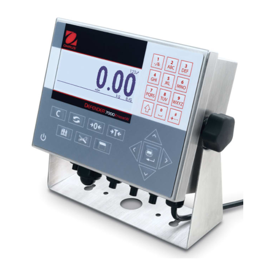
EN 12 7000 SERIES INDICATORS 1.13 Display and Keyboard The T72XW indicator uses a graphic, transflective type Liquid Crystal Display (LCD) with a white LED backlight. The front panel including the display and keypad is shown in Figure 1-14. Alphanumeric keypad LCD display Navigation... -
Page 21: Operation: Indicator
7000 SERIES INDICATORS EN 13 OPERATION: INDICATOR Overview This chapter provides information about the basic functionality of the T72XW indicator, including display operation, keypad functions and menu navigation. Operation of the indicator varies depending on which functions are enabled, and on the configuration of parameters in setup. -
Page 22: Keypad Operation
EN 14 7000 SERIES INDICATORS 2.2.2 Keypad Operation The front panel keys are used to operate and configure the T72XW. Alphanumeric Keypad The T72XW permits the entry of both alphabetical and numeric data, using the 12-element keypad to the right of the display. - Page 23 7000 SERIES INDICATORS EN 15 Table 2-2: Example Data Entry Sequence Entry Explanation and Notes Result SHIFT sets the input mode to ABC 8 inputs a T SHIFT sets the input mode to abc 4 4 inputs an h 3 3 inputs an e 0 enters a space SHIFT SHIFT returns input mode to ABC 8 inputs a T...
-
Page 24: Operator Menu
EN 16 7000 SERIES INDICATORS The ZERO and TARE functions will not operate when there is motion on the scale. If one of these keys is pressed while the scale is in motion, the command will be retained for the programmed number of seconds while the indicator waits for no-motion. - Page 25 7000 SERIES INDICATORS EN 17 Figure 2-3: Set Time & Date Here, items may be selected by number or by moving focus and pressing ENTER. Note that the header line reflects the currently displayed screen, and the input mode icon is also displayed at upper right.
- Page 26 EN 18 7000 SERIES INDICATORS Table 2-5: Operator Menu Icons Icon Function Description Standard Alibi Memory Displays the ALIBI SEARCH screen. Adjust Contrast Displays the ADJUST CONTRAST screen. Transaction Displays the TRANSACTION COUNTER screen. Counter Time and Date Displays the SET TIME & DATE screen. Displays the TOTALS screen.
-
Page 27: Alibi Memory
7000 SERIES INDICATORS EN 19 2.3.3 Alibi Memory The Alibi Memory key opens the ALIBI SEARCH screen. Here, the contents of Alibi Memory can be viewed and printed. The results can be filtered using comparisons with one or two search fields, and printed. The elements of this search screen are summarized in Table 2-6. -
Page 28: Totals Memory
EN 20 7000 SERIES INDICATORS 2.3.6 Totals Memory Depending on how the indicator is configured in setup at Application > Totalization, this screen displays the Grand Total of number of transactions and total weight, or both Grand Total and Subtotal of transactions with accumulated weight for each. -
Page 29: Setup Access
Option 1 Shows installed hardware options, if any. Option 2 Firmware Shows the firmware revision number. A telephone number used to contact OHAUS CORPORATION Service authorized service. Yes or No Approved Indicates whether the indicator has been programmed as Approved for use in legal for trade applications. -
Page 30: Tare
EN 22 7000 SERIES INDICATORS Automatic Zero Maintenance Automatic Zero Maintenance (AZM) enables the T72XW to compensate for the build up of small amounts of weight and track itself back to the center of zero. Within the AZM operating range (selectable from 0.5, 1, 3 or 10 divisions), when the indicator is in a no motion condition, it makes small adjustments to the current zero reading to drive the weight reading toward the true center-of-zero. - Page 31 7000 SERIES INDICATORS EN 23 Pushbutton Tare Disabled – If pushbutton tare is configured as disabled, the TARE scale function key will not initiate a semi-automatic tare. Negative Gross Weight – Any pushbutton tare attempted when the gross weight is at or below zero is ignored. Ensure that the gross weight is above zero.
- Page 32 EN 24 7000 SERIES INDICATORS Table 2-8: Weight Values With and Without Net Sign Correction Net Sign Correction Printed and Displayed Disabled Enabled Gross 16 kg 53 kg Tare 53 kg 16 kg 37 kg 37 kg Automatic Tare The T72XW can be configured so that tare is automatically taken (auto tare) after the weight on the scale exceeds a programmed tare threshold weight.
-
Page 33: Unit Switching
7000 SERIES INDICATORS EN 25 If the motion check is enabled, after meeting the requirements for weight value above and then below the threshold weight (auto clear threshold), the T72XW waits for a no-motion condition before automatically clearing the tare. ... -
Page 34: Information Recall
EN 26 7000 SERIES INDICATORS 2.4.6 Information Recall A limited number of data fields are made available for easy recall on the indicator display. These fields include data such as model, serial number, identification fields, hardware and software configuration, a service contact phone number and whether the indicator has been set up as approved for legal for trade operation. -
Page 35: Totalization
7000 SERIES INDICATORS EN 27 2.4.9 Totalization Knowing how many weighing transactions were performed and how much material was processed during a particular period of time is useful information for many weighing applications. The T72XW indicator provides both grand total (GT) and subtotal (ST) registers and counters. Counters have a limit of 1,500,000 and registers will accumulate up to 11 digits of weight, including any digits to the right of the decimal point. -
Page 36: Counting
EN 28 7000 SERIES INDICATORS Figure 2-11: Checkweighing Application Screen 2.5.3 Counting The Counting application offers the following capabilities: Variable sample selection that allows a numeric sample quantity to be entered via the numeric keypad. A prompt-based mode of operation. ... -
Page 37: Configuration: Indicator
7000 SERIES INDICATORS EN 29 CONFIGURATION: INDICATOR This chapter provides information about how to configure the T72XW indicator for the required application. It describes access to the setup mode, where functions can be enabled, disabled, or defined by entering parameter values in specific setup screens. -
Page 38: Navigation
EN 30 7000 SERIES INDICATORS 3.4.1 Navigation Each display of setup branches will include one branch shown in reverse video. This indicates the branch that has “focus”. The display of each setup branch will also include a number shown to the left of it. Navigation to a specific branch can be done two different ways. -
Page 39: Configuration
7000 SERIES INDICATORS EN 31 Data entry box with focus Insertion point for new text Figure 3-7: Setup Screen: Field Contents Select (top) and New Data Entered (bottom) To change the field value in a selection box: 1. Press the UP and DOWN navigation keys to scroll through the list and place the focus on the value to be selected. -
Page 40: Scale
EN 32 7000 SERIES INDICATORS Figure 3-8: T72XW Setup Menu Structure – Overview 3.5.1 Scale A detailed view of the Scale branch is shown in. This view indicates all the parameters in the Scale branch. Each of these setup parameters are described in this section. ... - Page 41 7000 SERIES INDICATORS EN 33 Figure 3-9: Scale Branch Menu Structure Type The Scale Type screen permits a name to be assigned to the scale, provides a selection list for the Approval region, and allows entry of the W&M certificate number associated with the region. The LEFT navigation key will return the display to the setup menu.
- Page 42 EN 34 7000 SERIES INDICATORS When an approval region is selected, the indicator will require that SW1-1 be turned ON before setup can be exited. If an approval is selected and SW1-1 is not ON, an error message of [Err 0001] will appear when trying to exit setup.
- Page 43 “Calibration Failure” displays. If the calibration fails, repeat the capture span procedures. If the calibration continues to fail, contact a local OHAUS CORPORATION representative for assistance. Press the LEFT navigation key to return to the Calibration screen.
- Page 44 EN 36 7000 SERIES INDICATORS This message functions only as a recommendation to recalibrate. After the warning message is acknowledged by pressing the ENTER key, the user is presented with the “Capture Span OK” screen. Service personnel should then carry out the following: ...
- Page 45 7000 SERIES INDICATORS EN 37 Tare Tare is used to subtract the weight of an empty container from the gross weight on the scale to determine the net weight of the contents. Tare is inhibited if the scale is in motion. Three setup screens are available to configure tare: Tare Types Auto Tare...
- Page 46 EN 38 7000 SERIES INDICATORS Tare Threshold Wt. When weight on the scale platform exceeds the tare threshold value and settles to no-motion, the indicator automatically tares. Reset Threshold Weight When the weight on the scale platform falls below the reset threshold value, such as when a load has been removed, the indicator automatically resets the auto tare trigger, depending upon the programming of motion checking.
- Page 47 7000 SERIES INDICATORS EN 39 Stability Filter The stability filter works in conjunction with the standard low pass filter to provide a more stable final weight reading. The stability filter should only be used in transaction weighing applications, since the nonlinear action of the filter switching may cause inaccurate cutoffs in filling applications.
-
Page 48: Application
“Reset Successful” displays If the reset was not successful, an error message that reads “Reset Failure” displays. If the reset fails, try to initiate the reset again. If the reset continues to fail, contact a local OHAUS CORPORATION representative for assistance. - Page 49 7000 SERIES INDICATORS EN 41 Figure 3-11: Application Branch Menu Structure Memory Memory setup screens includes parameters for Alibi Memory. Alibi Memory The Alibi Memory can be Enabled or Disabled in the selection box. Alibi Memory is configured as a “ring” buffer that overwrites the oldest record when it reaches its memory limit.
- Page 50 EN 42 7000 SERIES INDICATORS Totalization Use the Totalization setup screen to select parameters for totalization operations, including which source to use as input for totalization, settings for grand totals and subtotals, and to enable or disable the conversion of second unit weights for totalization.
- Page 51 7000 SERIES INDICATORS EN 43 Function Key The Function Key setup allows selection of the application that will be active when the FUNCTION key is pressed. Only one application can be selected. Assignment Options for the assignment of the FUNCTION key are: ...
- Page 52 EN 44 7000 SERIES INDICATORS Counting The following parameters are used to configure the Counting application. Figure 3-13: Application Menu – Counting Checkweighing The following parameters are used to configure the Checkweighing application. Application Checkweigh Operation Source Tolerance Type Target Editing Hold Timer Motion Check Display...
- Page 53 “Reset Successful” displays. If the reset was not successful, an error message that reads “Reset Failure” displays. If the reset fails, try to initiate the reset again. If the reset continues to fail, contact a local OHAUS CORPORATION representative for assistance. Press the LEFT navigation key to exit without resetting.
-
Page 54: Indicator
EN 46 7000 SERIES INDICATORS 3.5.3 Indicator A detailed view of the Indicator branch is shown in Figure 3-15. This view indicates all the parameters in the Indicator branch. Each of these setup parameters are described in this section. Figure 3-15: Indicator Branch Menu Structure Device The Device setup screen enables the entry of the indicator’s serial number and the keypad timeout value. - Page 55 7000 SERIES INDICATORS EN 47 Backlight Timeout This parameter selects the amount of time that the backlight will stay “On” after no-motion is detected and no keys are pressed. Select between Always On, Disabled (always off), 1 minute, 5 minutes or 10 minutes. System Line The system line is the top line of the display above the weight display.
- Page 56 EN 48 7000 SERIES INDICATORS Set Time & Date Enter the hour, minutes, day, month, and year on this setup screen’s text fields and selection boxes. The indicator automatically adjusts the date for a leap year, and a battery backup maintains the time and date settings in the event of a power outage.
- Page 57 Successful” displays. If the reset was not successful, an error message that reads “Reset Failure” displays. If the reset fails, try to initiate the reset again. If the reset continues to fail, contact a local OHAUS CORPORATION representative for assistance.
-
Page 58: Communication
EN 50 7000 SERIES INDICATORS 3.5.4 Communication A detailed view of the Communication branch is shown in Figure 3-16. This view indicates all the parameters in the Communication branch. Each of these setup parameters are described in this section. Communication Templates COM2 Output Templates... - Page 59 7000 SERIES INDICATORS EN 51 Table 3-2 lists the available items that can be selected for a field. Table 3-2: Items Used in Templates Item Length Item Length 3 spaces String 2 10 spaces String 3 15 spaces String 4 Date 8 or 11 String 5...
- Page 60 EN 52 7000 SERIES INDICATORS This is also useful when preparing a template for a printer that uses a different character set to print international characters. By entering the decimal value of the international character, new ASCII characters can be transmitted. When decimal entry is selected, an entry box below the string entry box will be shown.
- Page 61 7000 SERIES INDICATORS EN 53 Depending upon the assignment for a port, a template or checksum setup parameter will be shown. Refer to Table 3-5 for a list of the possible assignments for each port and the additional setup parameters required for that assignment.
- Page 62 EN 54 7000 SERIES INDICATORS Table 3-8: Ethernet Connection Assignments Port Assignment Template Assignment Demand Template 1, 2, 3, 4 - 9 Print Client Reports SICS Ethernet Assignment 2 (if Assignment = Demand or Reports) Demand Template 1, 2, 3, 4 - 9 Reports Assignment 3 (if Assignment 2 = Demand or Reports) Demand...
- Page 63 7000 SERIES INDICATORS EN 55 Use the COM1 setup screens to configure the parameters for the COM1 serial port. Baud Use the Baud selection box to set the baud rate for the serial port. Options are: 1200 4800 19200 57600 2400 9600 38400...
-
Page 64: Maintenance
“Reset Successful” displays If the reset was not successful, an error message that reads “Reset Failure” displays. If the reset fails, try to initiate the reset again. If the reset continues to fail, contact a local OHAUS CORPORATION representative for assistance. Press the LEFT navigation key to exit without resetting. - Page 65 7000 SERIES INDICATORS EN 57 Figure 3-17: Maintenance Branch Menu Structure Display Test The Display Test screen displays all dots “on” when first accessed. After three seconds, all dots turn “off”. This cycle will continue until the LEFT navigation key is pressed to return to the menu. Keyboard Test The Keyboard Test screen enables testing of the indicator keys, including Scale function keys, Navigation keys and Numeric keys.
- Page 66 This step provides access to a sequence used to replace the coin cell battery used to back up RAM memory. Details of this procedure are described in the Technical Manual in the Maintenance chapter. It is recommended that an authorized OHAUS CORPORATION service representative perform this service. GlobalTestSupply www.
- Page 67 Install Software Update This step is used to update the program in flash memory. Details of this procedure are described in the Technical Manual in the Maintenance chapter. It is recommended that an authorized OHAUS CORPORATION service representative perform this service.
- Page 68 Scale Reset, includes the reset of type, capacity, increment, or calibration data. Only a Master Reset will reset these parameters to factory default values. A Master Reset should only be performed by a trained OHAUS CORPORATION service technician. Figure 3-22: Reset All Setup Blocks GlobalTestSupply www.
-
Page 69: Applications: Configuration And Operation
7000 SERIES INDICATORS EN 61 APPLICATIONS: CONFIGURATION AND OPERATION Introduction Each of the following sections details operating procedures, operational features and function for the five applications included in the T72XW indicator. For information on general operation of the T72XW indicator, please refer to Chapter 2, Operation: Indicator. For information on general configuration of the T72XW indicator, please refer to Chapter 3, Configuration: Indicator. -
Page 70: Configuration
EN 62 7000 SERIES INDICATORS Tare A semi-automatic tare can be taken before the weighing cycle starts. Simply press the TARE key. A preset tare value can be entered using the numeric keypad. Use the numeric keys to enter the preset tare value. The digits will appear in line 2 of the lower part of the display, below the “Data:”... -
Page 71: Operating Sequence
7000 SERIES INDICATORS EN 63 Start Threshold The Start Threshold appears in the menu tree only when Auto Start is Enabled. It defines the scale weight value above which the averaging process will begin after stability is reached. Valid settings are from 0 to the full scale capacity. This value should be relatively high – for example, 80% of the estimated weight of all animals on the scale. -
Page 72: Serial Input Commands
EN 64 7000 SERIES INDICATORS The weight display will show dashes, and Line 1 will indicate Working and count down from the programmed Sampling Time while the averaging cycle is in process. When the cycle is complete, the averaged weight will be shown on the display, with an asterisk (*) to the left indicating that it is not a live scale weight. -
Page 73: Print Formats
7000 SERIES INDICATORS EN 65 4.2.6 Print Formats When a demand print is triggered in the Animal/Dynamic weighing application, the indicator will look for a demand connection to one of the ports using template 8. If such a connection exists, then template 8 will be sent out via the selected port. -
Page 74: Checkweighing (Over/Under)
EN 66 7000 SERIES INDICATORS {String 1} {New Line} {String 2} {New Line} {Time} {3 spaces} {3 spaces} {Date} {New Line} {ID} {New Line} Quantity: {# of Animals} {New Line} Avg. Wt.: {Avg. per Animal} {New Line} Total Wt.: {Averaged Total Weight} {New Line} {End of template} Figure 4-4: Suggested Structure of Template 8 for Mode 2 Figure 4-5: Print Sample, Format Modified for Mode 2... -
Page 75: Configuration
7000 SERIES INDICATORS EN 67 Tare A semi-automatic tare can be taken any time during the weighing cycle. Simply press the TARE key. A preset tare value can be entered using the numeric keypad. Use the numeric keys to enter the preset tare value. The digits will appear in line 2 of the lower part of the display, below the “Data:”... - Page 76 EN 68 7000 SERIES INDICATORS Source may be set as Displayed Weight (the default) or Gross Weight. If Displayed Weight is selected, the over/under function will work based on the displayed weight, either gross or net. If gross weight is selected, the target comparison will be based on the gross weight even if a tare is taken and a net weight is displayed.
- Page 77 7000 SERIES INDICATORS EN 69 If the feature accessed by the key must be enabled or configured separately, such as the Target Table, enabling its menu key will display the corresponding icon in the Operator Menu, but will not give access to the feature. Active Target By default, the Active Target is Enabled, so that the active target and tolerance values in use can be viewed by the Operator.
- Page 78 EN 70 7000 SERIES INDICATORS Automatic The count and total values for all IDs are cleared after printing a Target Table report. Manual Pressing the CLEAR key after the Target Table report has been printed clears the count and total values. Each record’s count and total values must be re-set to zero Disabled individually, in the Target Table view in setup, as described under...
-
Page 79: Operating Sequence
7000 SERIES INDICATORS EN 71 4.3.4 Operating Sequence The following sections describe operation of the Checkweighing application. Checkweighing Sequence Begin with the scale empty and the indicator in the Checkweighing application. Press ZERO to capture an accurate zero reference. Enter the target and tolerance values for the product to be weighed. There are several different methods to enter these values –... - Page 80 EN 72 7000 SERIES INDICATORS Tolerance = % of Target Value or Weight Deviation Field Explanation Target Weight value of target - Tolerance Lower and upper tolerance limits expressed as a percentage or as a weight + Tolerance Description A descriptive field for display and printing, comprising up to 20 characters Tolerance = Weight Value Field Explanation...
-
Page 81: Print Formats
7000 SERIES INDICATORS EN 73 Use the arrow keys to select the Target Table icon , then press ENTER The first record from the Target Table will appear. The data in each record will vary depending on the selected tolerance mode: If Tolerance = % of Target Value or Weight Deviation, the fields are: ID, Description, Target, Units, -Tol, +Tol If Tolerance = Weight Value, the fields are:... - Page 82 EN 74 7000 SERIES INDICATORS Figure 4-8: Print Sample, Default Template 6 This template can be edited, as described in the Communication section of Chapter 3 of this manual, Configuration > Communication > Templates. Report Format The Target Table Report can be configured as narrow (40 characters) or wide (80 characters) in setup at Communication >...
-
Page 83: Counting
7000 SERIES INDICATORS EN 75 Counting 4.4.1 Overview The T72XW Counting application provides a simple counting sequence that guides an operator through a sampling process to determine a count value. The counting application offers the following capabilities: Operator prompting. ... - Page 84 EN 76 7000 SERIES INDICATORS Figure 4-11: Counting Application Configuration Menu Operation Prompt The Prompt setting determines the sequence in which the operator is prompted to enter the tare weight and sample quantity. Options are Tare-Sample and Sample-Tare. The default is Tare-Sample. Auto Clear APW The Auto Clear APW setting determines whether the average piece weight value (APW) will be cleared when the scale returns to zero, or if the APW will be retained for the next counting sequence.
- Page 85 7000 SERIES INDICATORS EN 77 When Enabled, the Operator will be able to switch from the sampling mode of operation to manual entry of an APW value mode when prompted for Sample?. ID Memory ID Table When the ID Table is Enabled, stored tare and APW values in the ID Table can be recalled by ID for a quick counting sequence.
-
Page 86: Operating Sequences
EN 78 7000 SERIES INDICATORS The following keys can be used when creating a new ID record: LEFT arrow Return to ID Table view. UP and Navigates between the labels on the setup page. DOWN arrows ENTER Confirm entry and move to next parameter. 4.4.4 Operating Sequences The following sections describe operation of the counting application. - Page 87 7000 SERIES INDICATORS EN 79 11. Remove the container from the scale and the display will show a piece count equivalent to the tare weight. 12. If counting the same pieces again, place an empty container on the scale and press TARE to tare to net zero.
- Page 88 EN 80 7000 SERIES INDICATORS To change the mode from APW entry to Sampling: When the display is prompting APW?, press the MENU key to access the Operator Menu. Select the Sample/APW key and press ENTER The prompt will now show SAMPLE? and support part sampling to determine an APW. Clearing the Counting Cycle When the display is showing the number of pieces in a piece count, the display can be cleared back to the prompting sequence by pressing the CLEAR key...
-
Page 89: Print Formats
7000 SERIES INDICATORS EN 81 4.4.5 Print Format When a demand print is triggered in the Counting application, the indicator will look for a demand connection to one of the ports using template 9. If such a connection exists, then template 9 will be sent out via the selected port. If there is no demand connection using template 9, a “No demand connection”... -
Page 90: Overview
EN 82 7000 SERIES INDICATORS 12:27:43 15 Feb 2012 01 Blue cups 0123 kg 00 kg T 318 Pcs *************************************** 02 Red cups 0357 kg 00 kg T 285 Pcs *************************************** 03 Green cups 03466 kg 00 kg T 623 Pcs *************************************** Figure 4-14: Example of Printed ID Table Report, Narrow Format -- ID TABLE REPORT --... -
Page 91: Operational Features
7000 SERIES INDICATORS EN 83 4.5.3 Permanent Tare Weighing In this mode, the known tare weight for a vehicle is stored in the Permanent ID table, making one-pass weighing possible. When the full vehicle is on the weighing platform, the stored tare weight is recalled from memory by ID and an outbound process triggered. -
Page 92: Operation
EN 84 7000 SERIES INDICATORS Figure 4-18: Vehicle Application Configuration Menu 4.5.6 Operation The application can be configured with both Temporary and Permanent ID modes enabled. By default, Temporary ID is enabled and Permanent ID disabled. Temporary ID Can be Enabled (the default) or Disabled. When Enabled, the Temporary Tare mode will be accessible via the FUNCTION key allowing the indicator to store a weight value in the Temporary ID Table for each inbound vehicle. -
Page 93: General
7000 SERIES INDICATORS EN 85 Totalization Totalization appears only if Permanent ID mode is Enabled, and can be Disabled (the default) or Enabled. If enabled, the net weight for each Permanent Tare outbound transaction will be added to the totals value for that Permanent ID. -
Page 94: Operating Sequences
EN 86 7000 SERIES INDICATORS Records are shown in the order they were entered and, depending on which features are enabled, each will include ID, Description, Tare weight, the entered Variable data, and values for Count and Total. The UP and DOWN arrow keys scroll through the records, with one record displayed per screen. The following keys are functional in this screen: Function Used to begin entry of a new ID record. -
Page 95: Permanent Tare Operation
7000 SERIES INDICATORS EN 87 6. The ID, weight and variable information for the inbound transaction is now displayed for confirmation. If the data is correct, press PRINT to generate the inbound transaction. If any of the data is not accurate, press the CLEAR key to clear all data and return to the ID? prompt. - Page 96 EN 88 7000 SERIES INDICATORS When a no-motion condition is detected, the display will prompt ID?. Enter the alphanumeric identification (ID) for this vehicle. The ID can also be recalled by viewing the records in the Permanent ID Table and pressing ENTER when the desired record is displayed. When the ID entry is complete, press ENTER.
-
Page 97: Quick Print
7000 SERIES INDICATORS EN 89 4.5.12 Table Memory Limits The T72XW tables each have a limited capacity: Temporary ID Table 100 records Permanent ID Table 100 records Transaction Table 10,000 records Temporary and Permanent ID Tables When the Temporary and Permanent ID tables are full, an attempt to add a new record will cause a pop-up message –... - Page 98 EN 90 7000 SERIES INDICATORS The figure below shows an example of the inbound template’s print output, with the strings customized. Print Sample, Default Template 4: Jones Inc. Recycle Center Upper Arlington, OH 43085 -- INBOUND -- 15:24:33 May 17 2010 0000018 Temporary ID: BMR-4399...
- Page 99 7000 SERIES INDICATORS EN 91 Example of Temporary ID Report, Wide Format: -- TEMPORARY ID REPORT -- 12:29:31 16 Feb 2012 ABC-1234 18460 lb 9:24:16 16 Feb 2012 Copper Pipe ************************************************************************** XYZ-2468 14800 lb 9:28:41 16 Feb 2012 Copper Wire ************************************************************************** FGH-1357 15220 lb...
-
Page 100: Service And Maintenance
SERVICE AND MAINTENANCE The T72XW indicator is designed to provide years of dependable operation. However, OHAUS CORPORATION recommends that – as with any industrial measurement equipment – the indicator and the connected scale system be serviced periodically. Timely, factory-specified maintenance and calibration by a OHAUS CORPORATION authorized service technician will ensure and document accurate and dependable performance to specifications. -
Page 101: Power Test
AC power source. If a problem that is not listed in Table 5-1 occurs, or if the suggested fix does not resolve the problem, contact an authorized OHAUS CORPORATION service representative for assistance. -
Page 102: Internal Diagnostics
EN 94 7000 SERIES INDICATORS Error messages will be shown on the top line of the display and will overwrite the DIO status or time and date information if they have been enabled in setup. After the message is cleared, the display reverts to the previous data shown before the error was detected. - Page 103 7000 SERIES INDICATORS EN 95 Each of the diagnostic items is shown in the menu. The following diagnostic tests are included: Display Test When the display test is run, the indicator will display all dots on for approximately 4 seconds then all dots off for another 4 seconds.
- Page 104 EN 96 7000 SERIES INDICATORS Figure 5-3: Serial Test Display 2. During the test, a data string is output repeatedly approximately once every three seconds. The data is: [Testing COMx: nn] where “x” is the COM port and “nn” is an incrementing value beginning at 1 and continuing through 99 then starting over again.
-
Page 105: System Backup And Restore
The SD memory card is not hot-swappable. The SD memory media provided by OHAUS CORPORATION as an option has been fully tested for correct operation. While other SD memory media may work, some may not work correctly. OHAUS CORPORATION will only support correct operation of the SD memory card model offered as the T72XW indicator accessory. -
Page 106: Restore From Sd Memory Card
EN 98 7000 SERIES INDICATORS Figure 5-7: Inserting the SD Memory Card 2. Apply power, enter setup and access the backup procedure at Maintenance > Backup to SD. 3. At the Dataset Name parameter, press ENTER to program the saved file name. The file will be namedT72XW_nn where “nn”... -
Page 107: Upgrading Firmware
To exit without a master reset, do not press ENTER. Remove AC power. Return SW1-2 (and, if it was changed, SW1-4) to their original OFF positions. Reapply AC power. Upgrading Firmware Contact your local authorized OHAUS CORPORATION service representative for information on upgrading firmware. GlobalTestSupply www. .com Find Quality Products Online at: sales@GlobalTestSupply.com... -
Page 108: Compliance
This Class A digital apparatus complies with Canadian ICES-001. ISO 9001 Registration In 1994, OHAUS Corporation, USA, was awarded a certificate of registration to ISO 9001 by Bureau Veritus Quality International (BVQI), confirming that the OHAUS quality management system is compliant with the ISO 9001 standard’s requirements. - Page 109 Should this device be passed on to other parties (for private or professional use), the content of this regulation must also be related. Disposal instructions in Europe are available online at www.ohaus.com/weee. Thank you for your contribution to environmental protection.
-
Page 110: Appendix Adefault Templates
New Line End of template Checkweighing Application Template 4 - Checkweighing Element Data String 1 New Line String 2 New Line Time OHAUS 3 spaces T72XW 3 spaces 17:36 29/Mar/2012 0000003 Date Bag #24 New Line 34.51 kg Transaction #... - Page 111 Displayed Weight New Line End of template Animal/Dynamic weighing Application Template 5 – Animal/Dynamic weighing Element Data String 1 New Line String 2 OHAUS New Line T72XW Time 14:55 30/Mar/2012 3 spaces ACME FARMS 3 spaces Total Wt.: * 1835 lb...
-
Page 112: Appendix Balibi Memory
EN 104 7000 SERIES INDICATORS APPENDIX B ALIBI MEMORY Alibi Memory stores transaction information in a preset format that is not changeable. Alibi Memory can be enabled or disabled in setup at Application > Memory > Alibi. In order for the Alibi Memory to store transaction data, the optional SD memory card must be installed. - Page 113 7000 SERIES INDICATORS EN 105 Figure B-2: Alibi Search Results View The Alibi Memory cannot be manually cleared. It is automatically cleared after it has been disabled and enabled again in setup. Printing Alibi Memory Records Results of the Alibi Memory search can be printed directly from the view page. The print format is fixed with a few cosmetic programming selections described in Chapter 3.0, Configuration.
- Page 114 EN 106 7000 SERIES INDICATORS Wide Format, = Record Separator: -- ALIBI MEMORY REPORT -- 12:27:43 15 Jun 2011 14-Jun-2011 16:07:45 0000027 8.2 lb 0 lb T 8.2 lb ============================================================================ 14-Jun-2011 14:09:32 0000026 72.7 lb 0 lb T 72.7 lb ============================================================================ 14-Jun-2011 11:14:16...
-
Page 115: Appendix Ccommunications
7000 SERIES INDICATORS EN 107 APPENDIX C COMMUNICATIONS C.1 Serial Interface Parameters One standard serial port and one optional serial port are supported with the T72XW indicator. They are designated COM1 (standard port on the Main PCB) and COM2 (optional). COM1 provides an RS-232 interface only. - Page 116 EN 108 7000 SERIES INDICATORS Template 2 Scale Name Time Date 29.94 kg 10.32 kg 19.62 kg Template 3 29.94 kg 10.32 kg 19.62 kg Continuous Output Mode Printout string for g, kg, lb, oz units: Field Weight space Unit space Stability space...
- Page 117 C.2 Standard Interface Command Set (SICS) Protocol The T72XW indicator supports the OHAUS CORPORATION Standard Interface Command Set (MT-SICS), which is divided into four levels (0, 1, 2, 3), depending on the functionality of the device. This indicator supports parts of levels 0 and 1: ...
- Page 118 EN 110 7000 SERIES INDICATORS Version Number of the MT-SICS Each level of the MT-SICS has its own version number, which can be requested with the command I1 from level 0. This indicator supports: MT-SICS level 0, version 2.2x (except the ZI command) ...
- Page 119 7000 SERIES INDICATORS EN 111 Weight Value – Weighing result, which is shown as a number with 10 digits, including sign directly in front of the first digit. The weight value appears right justified. Preceding zeroes are suppressed with the exception of the zero to the left of the decimal point.
- Page 120 EN 112 7000 SERIES INDICATORS Tips for the Programmer Tips for creating a robust communication with the indicator using the SICS protocol include: Command and Response Improve the dependability of application software by having the program evaluate the response of the indicator to a command.
- Page 121 7000 SERIES INDICATORS EN 113 I1 – INQUIRY OF MT-SICS LEVEL AND MT-SICS VERSIONS Command: I1_A_“ ”_“2.2x”_“2.2x”_“ ”_“ ” Response: “” No Levels fully implemented 2.2x Level 0, version V2.2x 2.2x Level 1, version V2.2x “” No MT-SICS 2 commands “”...
- Page 122 EN 114 7000 SERIES INDICATORS S – SEND STABLE WEIGHT VALUE Command: Response: S_S_ _ _ _ _ 436.2_lb 436.2 stable displayed weight weight unit Response: Command understood, not executable at present. Response: Indicator in overload range. Response: Indicator in underload range. Comments The indicator will wait for up to 3 seconds after receiving an “S”...
- Page 123 7000 SERIES INDICATORS EN 115 Z – ZERO Command: Response: Command performed, meaning the scale was in gross mode, scale was stable and weight was within the zero capture range. Response: Command understood, not executable at present. Response: Upper limit of zero setting range exceeded. Response: Lower limit of zero setting range exceeded.
- Page 124 EN 116 7000 SERIES INDICATORS Comments Command to send the current stable weight once then continuously after every weight change greater or equal to the “value” a non-stable (dynamic) value followed by the next stable value. If no preset value is included, the weight change must be at least 12.5% of the last stable weight value an a minimum of 30d.
- Page 125 7000 SERIES INDICATORS EN 117 TI – TARE IMMEDIATELY Command: Response: TI_S_WeightValue_Unit Taring performed, stable tare value. Response: TI_D_WeightValue_Unit Taring performed, non-stable (dynamic) tare value. Response: TI_I Command understood, not executable at present. Response: TI_L The command is not executable. Response: TI_+ Upper limit of taring range exceeded.
- Page 126 EN 118 7000 SERIES INDICATORS Alibi Memory Report 14:23:47 25/May/2011 25-May-2011 14:22:06 0000014 11.6 kg T 15.4 kg N **************************************** 25-May-2011 14:22:50 0000015 11.6 kg T 15.4 kg N **************************************** Figure C-3: 40 Column Alibi Memory Print Example Alibi Memory Report 14:24:19 25/May/2011 25-May-2011...
- Page 127 7000 SERIES INDICATORS EN 119 Index Name Description 1 – g 2 – kg 3 – lb Unit 4 – t 5 – ton 0 – One range Number of ranges 1 – 2 ranges Range 1 capacity Manual entry 0 –...
- Page 128 EN 120 7000 SERIES INDICATORS Index Name Description 0 – Disabled Auto tare 1 – Enabled Tare threshold weight Manual entry Reset threshold weight Manual entry 0 – Disabled Auto tare motion check 1 – Enabled 0 – Disabled Auto clear tare 1 –...
- Page 129 7000 SERIES INDICATORS EN 121 Setup – Application (read and write) Index Name Description 0 – Disabled Alibi Memory 1 – Enabled 0 – None 1 – Displayed weight Totalization mode 2 – Gross weight 0 – Disabled Clear GT on print 1 –...
- Page 130 EN 122 7000 SERIES INDICATORS Index Name Description 0 – Disabled Function AutoStart 1 – Enabled 0 – 1 Animal Operation Mode 1 – 2 Sampling Time Manual Entry 0 – Disabled Auto Start 1 – Enabled Start Threshold Manual Entry 0 –...
- Page 131 7000 SERIES INDICATORS EN 123 Index Name Description 0 – No Display 1 – Actual Weight Over/Under Display Mode 2 – Target Difference 0 – Disabled 1 – ID 2 – Description Over/Under Display Line 1 3 – Target & Tolerance 4 –...
- Page 132 EN 124 7000 SERIES INDICATORS Setup – Indicator (read and write) Index Name Description Serial Number Manual Entry - 15 digits max 0 – Disabled 1 – 1 minute 2 – 5 minutes Screen Saver 3 – 10 minutes 4 – 30 minutes 0 –...
- Page 133 7000 SERIES INDICATORS EN 125 Index Name Description 1 – January 2 – February 3 – March 4 – April 5 – May 6 – June Set month 7 – July 8 – August 9 – September 10 – October 11 –...
- Page 134 EN 126 7000 SERIES INDICATORS Index Name Description 0 – None 1 – OH Continuous Output 2 – MT Continuous Output COM1 Assignment 3 - Demand Output 4 - Reports 5 – SICS 0 – Template 1 1 – Template 2 2 –...
- Page 135 7000 SERIES INDICATORS EN 127 Index Name Description 0 – None 1 – Demand Ethernet Assignment3 2 – Reports Ethernet Template3 [Refer to values for 434] 0 – None 1 – OH Continuous Output 2 – MT Continuous Output Print Client Assignment 3 - Demand Output 4 - Reports 5 –...
- Page 136 EN 128 7000 SERIES INDICATORS Index Name Description [Refer to values for 445] COM2 Data Bits [Refer to values for 446] COM2 Parity COM2 Flow Control [Refer to values for 447] 0 – RS232 COM2 Interface 1 – RS485 COM2 Address Manual entry 0 –...
- Page 137 7000 SERIES INDICATORS EN 129 Template Block (read and write) Index Name Description Output Template 1 – Add line feeds Manual entry 0 – 3 Spaces 1 – 10 Spaces 2 – 15 Spaces 3 – Date 4 – Displayed Weight 5 –...
- Page 138 EN 130 7000 SERIES INDICATORS Index Name Description Output Template 5 – Add Line Feeds Manual entry Output Template 5 – Field Content [Refer to values for 712] Array Output Template 6 – Add Line Feeds Manual Entry Output Template 6 – Field Content [Refer to values for 712] Array Output Template 7 –...
-
Page 139: Appendix Dgeo Codes
7000 SERIES INDICATORS EN 131 APPENDIX D GEO CODES The GEO code feature provided in the T72XW indicator permits calibration readjustment due to changes in elevation or latitude without reapplying test weights. This adjustment assumes a previously accurate calibration was done with the GEO code set properly for that original location and that the GEO code for the new location can be accurately determined. - Page 140 EN 132 7000 SERIES INDICATORS Height Above Sea Level, in Meters Latitude North 1300 1625 1950 2275 2600 2925 3250 or South, in Degrees and 1300 1625 1950 2275 2600 2925 3250 3575 Minutes Height Above Sea Level, in Feet 1060 2130 3200...
- Page 141 OHAUS products are warranted against defects in materials and workmanship from the date of delivery through the duration of the warranty period. During the warranty period OHAUS will repair, or, at its option, replace any component(s) that proves to be defective at no charge, provided that the product is returned, freight prepaid, to OHAUS.
- Page 142 GlobalTestSupply www. .com Find Quality Products Online at: sales@GlobalTestSupply.com...
- Page 143 OHAUS® is either registered trademarks or trademarks of OHAUS Corporation in the United States and/or other countries. Microsoft®, Windows® and Excel® are either registered trademarks or trademarks of Microsoft Corporation in the United States and/or other countries. OHAUS Corporation 7 Campus Drive...
Need help?
Do you have a question about the T72XW AM and is the answer not in the manual?
Questions and answers