OHAUS 7000 Series Instruction Manual
Indicators
Hide thumbs
Also See for 7000 Series:
- Instruction manual (72 pages) ,
- Service manual (107 pages) ,
- Instruction manual (143 pages)
Table of Contents
Advertisement
Quick Links
Advertisement
Table of Contents

Related Manuals for OHAUS 7000 Series


Summary of Contents for OHAUS 7000 Series
- Page 1 7000 Series Indicators Instruction Manual T72XW...
-
Page 5: Table Of Contents
TABLE OF CONTENTS INTRODUCTION ....................................1 ....................................1 ESCRIPTION ..................................... 1 EATURES ..................................... 1 PECIFICATIONS ..........................3 EFINITION OF IGNAL ARNINGS AND YMBOLS ................................... 3 AFETY RECAUTIONS ............................4 NSPECTION AND ONTENTS HECKLIST ................................... 4 HYSICAL IMENSIONS PCB ..................................... 5 .................................... - Page 6 3.5.1 Scale ....................................31 3.5.2 Application ..................................39 3.5.3 Terminal .................................... 43 3.5.4 Communication ................................. 48 3.5.5 Maintenance ..................................54 APPLICATIONS: CONFIGURATION AND OPERATION ......................... 59 ..................................... 59 NTRODUCTION ..................................59 NIMAL EIGHING 4.2.1 Overview ................................... 59 4.2.2 Operational Features ................................. 59 4.2.3 Configuration ..................................
-
Page 7: Introduction
7000 SERIES INDICATORS EN 1 INTRODUCTION Description The T72XW industrial scale terminal provides a compact yet flexible solution to a variety of weighing needs. Available as AC powered for stationary applications, this terminal is at home in virtually any industrial environment. - Page 8 EN 2 7000 SERIES INDICATORS T72XW Specifications Power Operates at 85–264 VAC, 49–61 Hz and includes a power cord configured for the country of use. Table 1-2. Power Consumption Refer to Values shown are with internal COM2/DIO option and Ethernet option installed and load cell input loaded with 8 x 350...
-
Page 9: Definition Of Signal Warnings And Symbols
7000 SERIES INDICATORS EN 3 Table 1-3: T72XW Power Consumption Input Voltage I (mA) P (W) 5V/50 Hz 110 V/50 Hz 240 V/50 Hz 264 V/50 Hz 85 V/60 Hz 110 V/60 Hz 240 V/60 Hz 264 V/60 Hz Values shown are with internal Ethernet option installed and load cell input loaded with 8 x 350 load cells. -
Page 10: Inspection And Contents Checklist
PROPERLY GROUNDED OUTLET ONLY. DO NOT REMOVE THE GROUND PRONG. DO NOT USE THE T72XW TERMINAL IN AREAS CLASSIFIED AS HAZARDOUS BECAUSE OF COMBUSTIBLE OR EXPLOSIVE ATMOSPHERES. CONTACT AN AUTHORIZED OHAUS REPRESENTATIVE FOR INFORMATION ABOUT HAZARDOUS AREA APPLICATIONS. WHEN THIS EQUIPMENT IS INCLUDED AS A COMPONENT PART... -
Page 11: Main Pcb
7000 SERIES INDICATORS EN 5 Main PCB The T72XW terminal’s main printed circuit board (PCB) provides the analog load cell scale interface, as well as the COM1 RS-232 serial port. The main board also contains the power input connection, display interface, keypad interface and six position DIP switch. -
Page 12: Sd Memory Option
EN 6 7000 SERIES INDICATORS 1.11.4 SD Memory Option An optional SD Memory card provides a medium on which to store files such as Alibi memory, IDs in the counting application and target weights in the checkweighing application. Note: The SD card is required for alibi memory. - Page 13 7000 SERIES INDICATORS EN 7 Installing Cables and Connectors Information for installing cables and connectors for the T72XW terminal is provided in this section, including: Ferrite Core Main Board Wiring Connections Wiring Connections for Options Ferrite Core In order to meet certain electrical noise emission limits and to protect the T72XW from external influences, it is necessary to install a ferrite core on the load cell cable connected to the terminal.
- Page 14 EN 8 7000 SERIES INDICATORS Load cell connections are made to the load cell connector located on the main board as shown in Figure The AC version of the T72XW terminal is designed to power up to ten 350-ohm load cells (or a minimum resistance of approximately 35 ohms).
- Page 15 7000 SERIES INDICATORS EN 9 COM1 Serial Port Connections The COM1 port provides an RS-232 connection for external serial devices. Figure 1-3 indicates which terminal carries which signal on the COM1 port. Make the connections as necessary. Terminal Signal Transmit RS-232...
- Page 16 EN 10 7000 SERIES INDICATORS Table 1-5: Switch 1 Functions Switch Functions Notes SW1-1 Metrology Security Switch (legal for trade) This is true even if the Scale When in the ON position, this switch prohibits changes to Approval parameter is selected metrological parameters in setup.
- Page 17 7000 SERIES INDICATORS EN 11 Clean any oil or other contaminants from the area of the overlay shown in Figure 1-8 where the capacity label will be added. Peel the backing from the label and adhere it to the overlay in the location shown in Figure 1-8, or another location acceptable to the local regulations.
-
Page 18: Display And Keyboard
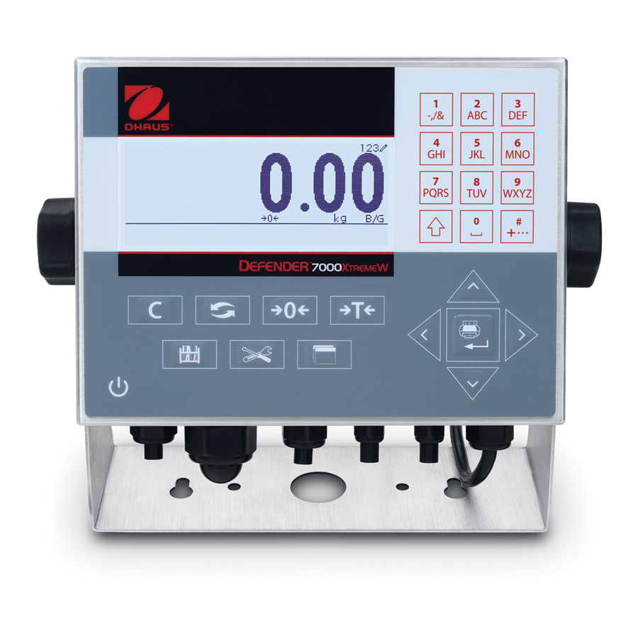
EN 12 7000 SERIES INDICATORS 1.13 Display and Keyboard The T72XW terminal uses a graphic, transflective type Liquid Crystal Display (LCD) with a white LED backlight. The front panel including the display and keypad is shown in Figure 1-. Alphanumeric... -
Page 19: Operation: Terminal
7000 SERIES INDICATORS EN 13 OPERATION: TERMINAL Overview This chapter provides information about the basic functionality of the T72XW terminal, including display operation, keypad functions and menu navigation. Operation of the terminal varies depending on which functions are enabled, and on the configuration of parameters in setup. -
Page 20: Keypad Operation
EN 14 7000 SERIES INDICATORS 2.2.2 Keypad Operation The front panel keys are used to operate and configure the T72XW. Alphanumeric Keypad The T72XW permits the entry of both alphabetical and numeric data, using the 12-element keypad to the right of the display. - Page 21 7000 SERIES INDICATORS EN 15 Table 2-3: Example Data Entry Sequence Entry Explanation and Notes Result SHIFT sets the input mode to ABC 8 inputs a T SHIFT sets the input mode to abc 4 4 inputs an h 3 3 inputs an e...
-
Page 22: Operator Menu
EN 16 7000 SERIES INDICATORS The ZERO and TARE functions will not operate when there is motion on the scale. If one of these keys is pressed while the scale is in motion, the command will be retained for the programmed number of seconds while the terminal waits for no-motion. - Page 23 7000 SERIES INDICATORS EN 17 Figure 2-4: Set Time & Date Here, items may be selected by number or by moving focus and pressing ENTER. Note that the header line reflects the currently displayed screen, and the input mode icon is also displayed at upper right.
-
Page 24: Alibi Memory
EN 18 7000 SERIES INDICATORS Icon Function Description Changes the main display to add an additional digit to the displayed weight. The appearance of the display will differ, Expand x10 depending on whether the terminal is in approved or non- approved mode. -
Page 25: Adjust Contrast
7000 SERIES INDICATORS EN 19 Figure 2-6: Alibi Search View Press the UP and DOWN arrow keys to scroll through the entries. Press the PRINT key to output the search results to a connected printer or the LEFT arrow to exit the view. -
Page 26: Expand X 10
Option 1 Shows installed hardware options, if any. Option 2 Firmware Shows the firmware revision number. A telephone number used to contact OHAUS CORPORTATION Service authorized service. Yes or No Approved Indicates whether the terminal has been programmed as Approved for use in legal for trade applications. -
Page 27: Setup Access
7000 SERIES INDICATORS EN 21 2.3.9 Setup Access The last icon displayed in the OPERATOR menu accesses the SETUP menu, from which all the terminal’s programming parameters can be viewed and modified. The settings and options available in setup are described in detail in Chapter 3, Configuration: Terminal. -
Page 28: Tare
EN 22 7000 SERIES INDICATORS 2.4.2 Tare Tare is the weight of an empty container. A tare value subtracts from the gross weight measurement, providing the computation of the net weight (material without the container). The tare function can also be used to track the net amount of material being added to or removed from a vessel or container. - Page 29 7000 SERIES INDICATORS EN 23 Several conditions could inhibit the preset tare function: Keyboard Tare Disabled – If keyboard tare is configured in setup as disabled, the numeric keypad and the TARE scale function key cannot be used to obtain a tare.
-
Page 30: Unit Switching
EN 24 7000 SERIES INDICATORS Motion Check – A motion check is provided to control the re-arming of the auto tare function. If disabled, the auto tare trigger will be reset as soon as the weight falls below the reset value. If enabled, the weight must settle to no-motion below the reset threshold before the next auto tare can be initiated. -
Page 31: Expand By 10
7000 SERIES INDICATORS EN 25 When switching units, the capacity of the converted units is dictated by the original number of divisions established in the capacity and increments area of setup. In some situations, this may reduce the capacity of the terminal when converting to second unit. -
Page 32: Time And Date
EN 26 7000 SERIES INDICATORS Pressing the ID key first Press the ID key . An "ID?" prompt will appear at the bottom of the display, with an entry box to its right. Using the alphanumeric keypad, enter the desired ID value and then press ENTER. The ID value will be shown at the bottom left of the display and will be available for printing. -
Page 33: Applications
7000 SERIES INDICATORS EN 27 Applications Each of the five applications is accessed by pressing the FUNCTION key . When this key is pressed, the terminal will leave normal weighing mode and enter whichever application mode is selected in setup at Application >... -
Page 34: Configuration: Terminal
EN 28 7000 SERIES INDICATORS CONFIGURATION: TERMINAL This chapter provides information about how to configure the T72XW terminal for the required application. It describes access to the setup mode, where functions can be enabled, disabled, or defined by entering parameter values in specific setup screens. -
Page 35: Setup Page
7000 SERIES INDICATORS EN 29 Traditional: Press the UP-DOWN-RIGHT navigation keys to move focus to the desired branch, then press ENTER. Shortcut: On the numeric keypad, press the number shown to the left of the desired branch. 3.4.2 Setup Page Whichever navigation mode is used, the selected setup page will display. -
Page 36: Configuration
EN 30 7000 SERIES INDICATORS Data entry box with focus Insertion point for new text Figure 3-7: Setup Screen: Field Contents Select (top) and New Data Entered (bottom) To change the field value in a selection box: 1. Press the UP and DOWN navigation keys to scroll through the list and place the focus on the value to be selected. -
Page 37: Scale
7000 SERIES INDICATORS EN 31 Figure 3-8: T72XW Setup Menu Structure – Overview 3.5.1 Scale A detailed view of the Scale branch is shown in. This view indicates all the parameters in the Scale branch. Each of these setup parameters are described in this section. - Page 38 EN 32 7000 SERIES INDICATORS Figure 3-9: Scale Branch Menu Structure Type The Scale Type screen permits a name to be assigned to the scale, provides a selection list for the Approval region, and allows entry of the W&M certificate number associated with the region. The LEFT navigation key will return the display to the setup menu.
- Page 39 7000 SERIES INDICATORS EN 33 When an approval region is selected, the terminal will require that SW1-1 be turned ON before setup can be exited. If an approval is selected and SW1-1 is not ON, an error message of [Err 0001] will appear when trying to exit setup.
- Page 40 “Calibration Failure” displays. If the calibration fails, repeat the capture span procedures. If the calibration continues to fail, contact a local OHAUS CORPORTATION representative for assistance. Press the LEFT navigation key to return to the Calibration screen.
- Page 41 7000 SERIES INDICATORS EN 35 This message functions only as a recommendation to recalibrate. After the warning message is acknowledged by pressing the ENTER key, the user is presented with the “Capture Span OK” screen. Service personnel should then carry out the following: ...
- Page 42 EN 36 7000 SERIES INDICATORS Tare Tare is used to subtract the weight of an empty container from the gross weight on the scale to determine the net weight of the contents. Tare is inhibited if the scale is in motion.
- Page 43 7000 SERIES INDICATORS EN 37 When weight on the scale platform exceeds the tare threshold value and settles to no-motion, the terminal automatically tares. Reset Threshold Weight When the weight on the scale platform falls below the reset threshold value, such as when a load has been removed, the terminal automatically resets the auto tare trigger, depending upon the programming of motion checking.
- Page 44 EN 38 7000 SERIES INDICATORS No-motion Interval The no motion interval defines the amount of time (seconds) that the scale weight must be within the motion range to have a no-motion condition. Select a value from 0.3, 0.5, 0.7 or 1.0 seconds. A shorter interval means that a no- motion condition is more likely, but may cause the terminal to indicate no-motion while there is still a small amount of motion on the scale.
-
Page 45: Application
“Reset Successful” displays If the reset was not successful, an error message that reads “Reset Failure” displays. If the reset fails, try to initiate the reset again. If the reset continues to fail, contact a local OHAUS CORPORTATION representative for assistance. - Page 46 EN 40 7000 SERIES INDICATORS The use of Alibi Memory requires installation of an SD memory card. Attempts to generate a print transaction from the front panel without an SD card installed return a pop-up error message SD card is not installed., while a print command issued serially or via an input will result in an SD memory card not installed message in the system line.
- Page 47 7000 SERIES INDICATORS EN 41 Assignment Options for input assignment are: None (default) SICS – S Tare Blank Display SICS – SI Unit Switching Clear Tare SICS – SIR Zero Print...
- Page 48 EN 42 7000 SERIES INDICATORS Animal Weighing The following parameters are used to configure the Animal Weighing application. Figure 3-12: Application Menu – Animal Weighing Counting The following parameters are used to configure the Counting application. Figure 3-13: Application Menu – Counting...
- Page 49 “Reset Successful” displays If the reset was not successful, an error message that reads “Reset Failure” displays. If the reset fails, try to initiate the reset again. If the reset continues to fail, contact a local OHAUS CORPORTATION representative for assistance. Press the LEFT navigation key to exit without resetting.
-
Page 50: Terminal
EN 44 7000 SERIES INDICATORS 3.5.3 Terminal A detailed view of the Terminal branch is shown in Figure 3-15. This view indicates all the parameters in the Terminal branch. Each of these setup parameters are described in this section. Figure 3-15: Terminal Branch Menu Structure Device The Device setup screen enables the entry of the terminal’s serial number and the keypad timeout value. - Page 51 7000 SERIES INDICATORS EN 45 Backlight Timeout This parameter selects the amount of time that the backlight will stay “On” after no-motion is detected and no keys are pressed. Select between Always On, Disabled (always off), 1 minute, 5 minutes or 10 minutes.
- Page 52 EN 46 7000 SERIES INDICATORS Set Time & Date Enter the hour, minutes, day, month, and year on this setup screen’s text fields and selection boxes. The terminal automatically adjusts the date for a leap year, and a battery backup maintains the time and date settings in the event of a power outage.
- Page 53 Successful” displays If the reset was not successful, an error message that reads “Reset Failure” displays. If the reset fails, try to initiate the reset again. If the reset continues to fail, contact a local OHAUS CORPORTATION representative for assistance.
-
Page 54: Communication
EN 48 7000 SERIES INDICATORS 3.5.4 Communication A detailed view of the Communication branch is shown in Figure 3-16. This view indicates all the parameters in the Communication branch. Each of these setup parameters are described in this section. Communication... - Page 55 7000 SERIES INDICATORS EN 49 Table 3-2 lists the available items that can be selected for a field. Table 3-2: Items Used in Templates Item Length Item Length 3 spaces String 2 10 spaces String 3 15 spaces String 4...
- Page 56 EN 50 7000 SERIES INDICATORS Note that decimal values from 32 to 255 can be entered. Control characters in decimal values 0 to 31 cannot be entered using this method. Control characters can be included in a template created using the InSite software.
- Page 57 7000 SERIES INDICATORS EN 51 Table 3-5: COM1 Connection Assignments Port Assignment Template Checksum Assignment Continuous Output Disabled, Enabled Continuous-Extended Disabled, Enabled Demand Template 1, 2, 3, 4 - 9 Reports SICS Variable Access COM1 Assignment 2 (if Assignment = Demand or Reports)
- Page 58 EN 52 7000 SERIES INDICATORS Table 3-8: Ethernet Connection Assignments Port Assignment Template Assignment Demand Template 1, 2, 3, 4 - 9 Print Client Reports SICS Variable Access Ethernet Assignment 2 (if Assignment = Demand or Reports) Demand Template 1, 2, 3, 4 - 9...
- Page 59 7000 SERIES INDICATORS EN 53 Serial Serial communication setup screens provide access to the communication parameters for the serial ports COM1 and COM2/USB. The COM2 port and USB port share the same setup parameters as only one of them can be installed into the terminal at one time.
- Page 60 “Reset Successful” displays If the reset was not successful, an error message that reads “Reset Failure” displays. If the reset fails, try to initiate the reset again. If the reset continues to fail, contact a local OHAUS CORPORTATION representative for assistance. Press the LEFT navigation key to exit without resetting.
-
Page 61: Maintenance
7000 SERIES INDICATORS EN 55 3.5.5 Maintenance A detailed view of the Maintenance branch is shown in Figure 3-17. This view indicates all the parameters in the Maintenance branch. Each of these setup parameters are described in this section. Figure 3-17: Maintenance Branch Menu Structure Display Test The Display Test screen displays all dots “on”... - Page 62 EN 56 7000 SERIES INDICATORS The Calibration Values screen displays the current calibration values for the scale. The number of test loads that display calibration values is determined by the Linearity Adjustment setting configured for the scale (see Scale >...
- Page 63 Install Software Update This step is used to update the program in flash memory. Details of this procedure are described in the Technical Manual in the Maintenance chapter. It is recommended that an authorized OHAUS CORPORTATION service representative perform this service.
- Page 64 Scale Reset, includes the reset of type, capacity, increment, or calibration data. Only a Master Reset will reset these parameters to factory default values. A Master Reset should only be performed by a trained OHAUS CORPORTATION service technician. Figure 3-22: Reset All Setup Blocks...
-
Page 65: Applications: Configuration And Operation
7000 SERIES INDICATORS EN 59 APPLICATIONS: CONFIGURATION AND OPERATION Introduction Each of the following sections details operating procedures, operational features and function for the five applications included in the T72XW terminal. For information on general operation of the T72XW terminal, please refer to Chapter 2, Operation: Terminal. -
Page 66: Configuration
EN 60 7000 SERIES INDICATORS Tare A semi-automatic tare can be taken before the weighing cycle starts. Simply press the TARE key. A preset tare value can be entered using the numeric keypad. Use the numeric keys to enter the preset tare value. -
Page 67: Operating Sequence
7000 SERIES INDICATORS EN 61 Start Threshold The Start Threshold appears in the menu tree only when Auto Start is Enabled. It defines the scale weight value above which the averaging process will begin after stability is reached. Valid settings are from 0 to the full scale capacity. This value should be relatively high – for example, 80% of the estimated weight of all animals on the scale. -
Page 68: Serial Input Commands
EN 62 7000 SERIES INDICATORS The weight display will show dashes, and Line 1 will indicate Working and count down from the programmed Sampling Time while the averaging cycle is in process. When the cycle is complete, the averaged weight will be shown on the display, with an asterisk (*) to the left indicating that it is not a live scale weight. -
Page 69: Print Formats
7000 SERIES INDICATORS EN 63 4.2.6 Print Formats When a demand print is triggered in the Animal Weighing application, the terminal will look for a demand connection to one of the ports using template 8. If such a connection exists, then template 8 will be sent out via the selected port. -
Page 70: Checkweighing (Over/Under)
EN 64 7000 SERIES INDICATORS {End of template} Figure 4-4: Suggested Structure of Template 8 for Mode 2 Figure 4-5: Print Sample, Format Modified for Mode 2 Checkweighing (Over/Under) 4.3.1 Overview In the Over/Under application, the T72XW compares weight on the scale to a stored target weight, and indicates the status of the comparison on screen. -
Page 71: Configuration
Target Table Import and Export The OHAUS CORPORTATION T72XW File Transfer Tool (FTT) program, included on the T72XW Resource CD- ROM, runs on a PC to exchange application files and tables with the T72XW terminal. Refer to the User's Guide of the File Transfer Tool for details. - Page 72 EN 66 7000 SERIES INDICATORS Source may be set as Displayed Weight (the default) or Gross Weight. If Displayed Weight is selected, the over/under function will work based on the displayed weight, either gross or net. If gross weight is selected, the target comparison will be based on the gross weight even if a tare is taken and a net weight is displayed.
- Page 73 7000 SERIES INDICATORS EN 67 If the feature accessed by the key must be enabled or configured separately, such as the Target Table, enabling its menu key will display the corresponding icon in the Operator Menu, but will not give access to the feature.
- Page 74 EN 68 7000 SERIES INDICATORS Manual Pressing the CLEAR key after the Target Table report has been printed clears the count and total values. Each record’s count and total values must be re-set to zero Disabled individually, in the Target Table view in setup, as described under View Table, below.
-
Page 75: Operating Sequence
7000 SERIES INDICATORS EN 69 4.3.4 Operating Sequence The following sections describe operation of the checkweighing application. Checkweighing Sequence Begin with the scale empty and the terminal in the Checkweighing application. Press ZERO to capture an accurate zero reference. Enter the target and tolerance values for the product to be weighed. There are several different methods to enter these values –... - Page 76 EN 70 7000 SERIES INDICATORS Figure 4-8: SmartTrac Graphic Display, Zones Not Activated: Small (top) and large (bottom) Target Entry Target parameters for the T72XW Checkweighing application can be entered in any of five ways: by accessing Active Values from the Operator...
- Page 77 7000 SERIES INDICATORS EN 71 Over Limit Description A descriptive field for display and printing, comprising up to 20 characters When editing of a value is complete, press ENTER to confirm. After editing all values, press the LEFT arrow and the display will return to the Checkweighing run display.
-
Page 78: Print Formats
EN 72 7000 SERIES INDICATORS Use the UP and DOWN arrows to move focus from one record to the next until the desired record is shown. Press ENTER to select it and return to the Checkweighing run display, or the LEFT arrow to return to the Operator Menu without selecting a new set of target parameters. -
Page 79: Counting
7000 SERIES INDICATORS EN 73 This template can be edited, as described in the Communication section of Chapter 3 of this manual, Configuration > Communication > Templates. Report Format The Target Table Report can be configured as narrow (40 characters) or wide (80 characters) in setup at Communication >... -
Page 80: Operational Features
EN 74 7000 SERIES INDICATORS 4.4.2 Operational Features In addition to the fundamental weighing functions, the following T72XW terminal basic weighing features can also be used within the Counting application. Semi-Automatic Tare When the Tare? prompt is displayed on the terminal, press TARE and the scale will tare to net zero. - Page 81 7000 SERIES INDICATORS EN 75 The Prompt setting determines the sequence in which the operator is prompted to enter the tare weight and sample quantity. Options are Tare-Sample and Sample-Tare. The default is Tare-Sample. Auto Clear APW The Auto Clear APW setting determines whether the average piece weight value (APW) will be cleared when the scale returns to zero, or if the APW will be retained for the next counting sequence.
-
Page 82: Operating Sequences
EN 76 7000 SERIES INDICATORS Function Opens ID NEW screen, where a new ID can be set up. Prompts Delete record? Press ENTER to confirm and (CLEAR) delete the displayed record, LEFT arrow to display a message, Delete all records? Press ENTER to confirm and delete all records, LEFT arrow to return to the view without deleting. - Page 83 7000 SERIES INDICATORS EN 77 If the displayed sample quantity is correct, press the ENTER key to start the sampling cycle. If the sample quantity is not correct, use the numeric keypad to enter the correct sample quantity and then press the ENTER The main display will change from showing weight to showing the piece count.
- Page 84 EN 78 7000 SERIES INDICATORS As pieces are removed the count will update in a negative direction. Sample-Tare Place the sample pieces on the empty scale and press ENTER At the Tare? prompt, place the full container on the scale and press ENTER The terminal will display a count of zero pieces.
-
Page 85: Print Formats
7000 SERIES INDICATORS EN 79 If the ID is not known, the record can be found by viewing the ID Table. If the ID is known, it can be entered in a Quick Recall sequence. Recall from ID Table... - Page 86 EN 80 7000 SERIES INDICATORS {String 1} {New line} {String 2} {New line} {Time} {3 spaces} {3 spaces} {Date} {New line} {Displayed Weight} {New line} {Piece Count} {New line} {Record Description} {New line} {End of template} Figure 4-14: Default Structure of Template 9...
- Page 87 7000 SERIES INDICATORS EN 81...
-
Page 88: Service And Maintenance
SERVICE AND MAINTENANCE The T72XW terminal is designed to provide years of dependable operation. However, OHAUS CORPORTATION recommends that – as with any industrial measurement equipment – the terminal and the connected scale system be serviced periodically. Timely, factory-specified maintenance and calibration by a OHAUS CORPORTATION authorized service technician will ensure and document accurate and dependable performance to specifications. -
Page 89: Power Test
AC power source. If a problem that is not listed in Table 5-1 occurs, or if the suggested fix does not resolve the problem, contact an authorized OHAUS CORPORTATION service representative for assistance. -
Page 90: Internal Diagnostics
EN 84 7000 SERIES INDICATORS Error messages will be shown on the top line of the display and will overwrite the DIO status or time and date information if they have been enabled in setup. After the message is cleared, the display reverts to the previous data shown before the error was detected. - Page 91 7000 SERIES INDICATORS EN 85 Each of the diagnostic items is shown in the menu. The following diagnostic tests are included: Display Test When the display test is run, the terminal will display all dots on for approximately 4 seconds then all dots off for another 4 seconds.
- Page 92 EN 86 7000 SERIES INDICATORS Figure 5-3: Serial Test Display During the test, a data string is output repeatedly approximately once every three seconds. The data is: [Testing COMx: nn] where “x” is the COM port and “nn” is an incrementing value beginning at 1 and continuing through 99 then starting over again.
-
Page 93: System Backup And Restore
The SD memory card is not hot-swappable. The SD memory media provided by OHAUS CORPORTATION as an option has been fully tested for correct operation. While other SD memory media may work, some may not work correctly. OHAUS CORPORTATION will only support correct operation of the SD memory card model offered as the T72XW terminal accessory. -
Page 94: Restore From Sd Memory Card
EN 88 7000 SERIES INDICATORS Figure 5-7: Inserting the SD Memory Card Apply power, enter setup and access the backup procedure at Maintenance > Backup to SD. At the Dataset Name parameter, press ENTER to program the saved file name. The file will be namedT72XW_nn where “nn”... -
Page 95: Upgrading Firmware
To exit without a master reset, do not press ENTER. Remove AC power. Return SW1-2 (and, if it was changed, SW1-4) to their original OFF positions. Reapply AC power. Upgrading Firmware Contact your local authorized OHAUS CORPORTATION service representative for information on upgrading firmware. - Page 96 EN 90 7000 SERIES INDICATORS...
-
Page 97: Compliance
7000 SERIES INDICATORS EN 91 COMPLIANCE Compliance to the following standards is indicated by the corresponding mark on the product. Mark Standard This product conforms to the EMC Directive 2004/108/EC, the Low Voltage Directive 2006/95/EC and the Non-automatic Weighing Instruments Directive 2009/23/EC. - Page 98 7000 SERIES INDICATORS ISO 9001 Registration In 1994, OHAUS Corporation, USA, was awarded a certificate of registration to ISO 9001 by Bureau Veritus Quality International (BVQI), confirming that the OHAUS quality management system is compliant with the ISO 9001 standard’s requirements. On June 21, 2012, OHAUS Corporation, USA, was re-registered to the ISO 9001:2008 standard.
-
Page 99: Appendix Adefault Templates
7000 SERIES INDICATORS EN 93 APPENDIX A DEFAULT TEMPLATES Basic Functionality Template 1 – Multiple Line G T N Element Data Gross Weight 13.73 kg New Line 2.00 kg Tare Weight 11.73 kg New Line Net Weight New Line End of template Template 2 –... - Page 100 EN 94 7000 SERIES INDICATORS Template 4 - Checkweighing Element Data Displayed Weight New Line End of template Animal Weighing Application Template 5 – Animal Weighing Element Data String 1 New Line String 2 OHAUS New Line T72XW Time 14:55...
-
Page 101: Appendix Balibi Memory
7000 SERIES INDICATORS EN 95 APPENDIX B ALIBI MEMORY Alibi memory stores transaction information in a preset format that is not changeable. Alibi memory can be enabled or disabled in setup at Application > Memory > Alibi. In order for the Alibi memory to store transaction data, the optional SD memory card must be installed. - Page 102 EN 96 7000 SERIES INDICATORS Figure B-2: Alibi Search Results View The Alibi Memory cannot be manually cleared. It is automatically cleared after it has been disabled and enabled again in setup. Printing Alibi Memory Records Results of the Alibi Memory search can be printed directly from the view page. The print format is fixed with a few cosmetic programming selections described in Chapter 3.0, Configuration.
- Page 103 7000 SERIES INDICATORS EN 97 -- ALIBI MEMORY REPORT -- 12:27:43 15 Jun 2011 14-Jun-2011 16:07:45 0000027 8.2 lb 0 lb T 8.2 lb ============================================================================ 14-Jun-2011 14:09:32 0000026 72.7 lb 0 lb T 72.7 lb ============================================================================ 14-Jun-2011 11:14:16 0000025 33.3 kg 11.6 kg T...
-
Page 104: Appendix Ccommunications
EN 98 7000 SERIES INDICATORS APPENDIX C COMMUNICATIONS C.1 Serial Interface Parameters One standard serial port and one optional serial port are supported with the T72XW terminal. They are designated COM1 (standard port on the Main PCB) and COM2 (optional). - Page 105 C.2 Standard Interface Command Set (SICS) Protocol The T72XW terminal supports the OHAUS CORPORTATION Standard Interface Command Set (MT-SICS), which is divided into four levels (0, 1, 2, 3), depending on the functionality of the device. This terminal supports parts of levels 0 and 1: ...
- Page 106 EN 100 7000 SERIES INDICATORS Command Formats Each command received by the terminal via the SICS interface is acknowledged by a response to the transmitting device. Commands and responses are data strings with a fixed format. Commands sent to the terminal comprise one or more characters of the ASCII character set.
- Page 107 7000 SERIES INDICATORS EN 101 Comment – the <CR> and <LF> characters will not be shown in this description. Example Response with a stable weight value of 0.256 kg: S _ S_ _ _ _ _ _ 0.256 _ kg...
- Page 108 EN 102 7000 SERIES INDICATORS Reset When establishing communication between the terminal and system, send a reset command to the terminal to enable a start from a determined state. When the terminal or system is switched on or off, faulty characters can be received or sent.
- Page 109 7000 SERIES INDICATORS EN 103 I1 – INQUIRY OF MT-SICS LEVEL AND MT-SICS VERSIONS Command: I1_A_“ ”_“2.2x”_“2.2x”_“ ”_“ ” Response: “” No Levels fully implemented 2.2x Level 0, version V2.2x 2.2x Level 1, version V2.2x “” No MT-SICS 2 commands “”...
- Page 110 EN 104 7000 SERIES INDICATORS Comments The serial number response is the content of the terminal serial number variable (#301) as entered in setup. S – SEND STABLE WEIGHT VALUE Command: Response: S_S_ _ _ _ _ 436.2_lb 436.2 stable displayed weight...
- Page 111 7000 SERIES INDICATORS EN 105 S_S_ _ _ _ _ 129.09_kg S_S_ _ _ _ _ 129.09_kg S_D_ _ _ _ _ 114.87_kg . . . The scale continues to send stable or dynamic weight values Comments The SIR command is overwritten and cancelled by the commands S, SI, SR, and @.
- Page 112 EN 106 7000 SERIES INDICATORS Commands and Responses MT-SICS Level 1 The following commands of MT-SICS level 1 are available: Send weight value on weight change (Send and Repeat) Tare Set or inquiry of preset tare value Clear tare value Tare Immediately SR –...
- Page 113 7000 SERIES INDICATORS EN 107 Response: Command understood, not executable at present. Response: Upper limit of zero setting range exceeded. Response: Lower limit of zero setting range exceeded. Comments The existing tare will be overwritten and replaced by the new preset tare weight value.
- Page 114 EN 108 7000 SERIES INDICATORS Response: TI_- Lower limit of taring range exceeded. Example Command: Response: TI_D_ _ _ _117.57_kg Tare taken with dynamic weight value. Comments Any previous tare value will be overwritten by the new tare weight value.
- Page 115 7000 SERIES INDICATORS EN 109 Totals Report The totals report will print only the fields that have been enabled for the totalizing function. If the subtotal feature has been disabled, then that field will not display or print. The example in Figure C-3 below includes both the subtotal and grand total fields.
- Page 116 EN 110 7000 SERIES INDICATORS Write request: W(index#)<SP>xxxxx<CR><LF> Write target value : W611<SP>42.75<CR><LF> Response 1 (valid): <ACK><CR><LF> (data is accepted) Response 2 (error): <NAK><CR><LF> (data or variable is invalid) Blocks of Variables An entire block of data can be read or written at one time by using the index of an entire block (such as 100, 200, etc.).
- Page 117 7000 SERIES INDICATORS EN 111 Index Name Description Notes 0 – zero not captured since power up 1 – zero captured after power up Always “1” Format: weight<SP>unit. Weight is always 8 characters (including Weight unit is Tare Weight decimal) with leading spaces and included.
- Page 118 EN 112 7000 SERIES INDICATORS Index Name Description Notes 0 – None Network Interface 1 – Ethernet Option Board #.## if released or #.##xdd-mmm- Examples: 1.00 Firmware yy if not released (released), 0.13x14- Version Oct-08 (unreleased) SW1-1 W&M Security SW1-1...
- Page 119 7000 SERIES INDICATORS EN 113 Index Name Description Notes 0 – Turn DIO Output 1 OFF Output 1 1 – Turn DIO Output 1 ON Control 0 – Turn DIO Output 2 OFF Output 2 1 – Turn DIO Output 2 ON Control 0 –...
- Page 120 EN 114 7000 SERIES INDICATORS Index Name Description 0 – 0.0001 1 – 0.0002 2 – 0.0005 3 – 0.001 4 – 0.002 5 – 0.005 6 – 0.01 7 – 0.02 8 – 0.05 9 – 0.1 Range 1 increment size 10 –...
- Page 121 7000 SERIES INDICATORS EN 115 Index Name Description 0 – Disabled Auto clear tare 1 – Enabled Clear threshold weight Manual entry 0 – Disabled Auto clear tare motion check 1 – Enabled 0 – Disabled Clear after print 1 – Enabled 0 –...
- Page 122 EN 116 7000 SERIES INDICATORS Index Name Description 0 – None 1 – Displayed weight Totalization mode 2 – Gross weight 0 – Disabled Clear GT on print 1 – Enabled 0 – Disabled Subtotal 1 – Enabled 0 – Disabled Clear ST on print 1 –...
- Page 123 7000 SERIES INDICATORS EN 117 Index Name Description 0 – Disabled Auto Start 1 – Enabled Start Threshold Manual Entry 0 – Disabled Auto Print 1 – Enabled Print Delay Manual Entry 0 – Disabled 1 – Average Animal Application Display 2 –...
- Page 124 EN 118 7000 SERIES INDICATORS Index Name Description 0 – Disabled 1 – ID 2 – Description Over/Under Display Line 1 3 – Target & Tolerance 4 – Zone 0 – Disabled SmartTrac 1 – Enabled 0 – Disabled Over/Under Motion Blanking 1 –...
- Page 125 7000 SERIES INDICATORS EN 119 Index Name Description 0 – 12:MM 1 – 12:MM:SS Time Format 2 – 24:MM 3 – 24:MM:SS 0 – DD/MM/YY 1 – DD/MMM/YYYY 2 – MM/DD/YY Date format 3 – MMM/DD/YYYY 4 – YY/MM/DD 5 –YYYY/MMM/DD...
- Page 126 EN 120 7000 SERIES INDICATORS Index Name Description 0 – Disabled Operator menu – Totals Memory 1 – Enabled 0 – Disabled Operator menu – x10 1 – Enabled Setup – Communication (read and write) Index Name Description Communication Serial Block...
- Page 127 7000 SERIES INDICATORS EN 121 Index Name Description Template #4 added line feeds Manual entry Output template #5 field content array [Refer to values for 402] Template #5 added line feeds Manual entry Template #6 added line feeds Manual entry...
- Page 128 EN 122 7000 SERIES INDICATORS Index Name Description 0 – None 1 – Continuous Output 2 – Continuous-Extended Output 3 - Demand Output COM2 Assignment 4 - Reports 5 – SICS 6 – Cont. Multi 1 7 – Cont. Multi 2...
- Page 129 7000 SERIES INDICATORS EN 123 Index Name Description Ethernet Subnet Mask Manual entry Ethernet gateway Manual entry Print Client Server IP Address Manual entry Print Client Server TCP Port Manual entry Setup – Maintenance (read only) Index Name Description Maintenance Block...
-
Page 130: Appendix Dgeo Codes
EN 124 7000 SERIES INDICATORS APPENDIX D GEO CODES The GEO code feature provided in the T72XW terminal permits calibration readjustment due to changes in elevation or latitude without reapplying test weights. This adjustment assumes a previously accurate calibration was done with the GEO code set properly for that original location and that the GEO code for the new location can be accurately determined. - Page 131 7000 SERIES INDICATORS EN 125 Height Above Sea Level, in Meters Latitude North 1300 1625 1950 2275 2600 2925 3250 or South, in Degrees and 1300 1625 1950 2275 2600 2925 3250 3575 Minutes Height Above Sea Level, in Feet...
- Page 132 Ohaus. In lieu of a properly returned warranty registration card, the warranty period shall begin on the date of shipment to the authorized dealer. No other express or implied warranty is given by Ohaus Corporation. Ohaus Corporation shall not be liable for any consequential damages.
- Page 134 Ohaus® is either registered trademarks or trademarks of Ohaus Corporation in the United States and/or other countries. Microsoft®, Windows® and Excel® are either registered trademarks or trademarks of Microsoft Corporation in the United States and/or other countries. Ohaus Corporation 7 Campus Drive...
Need help?
Do you have a question about the 7000 Series and is the answer not in the manual?
Questions and answers