OHAUS T51P Instruction Manual
5000 series
Hide thumbs
Also See for T51P:
- Instruction manual (64 pages) ,
- Service manual (42 pages) ,
- User manual (61 pages)

Related Manuals for OHAUS T51P


Summary of Contents for OHAUS T51P
- Page 1 5000 Series Indicators Instruction Manual T51P Indicator T51XW Indicator GlobalTestSupply www. .com Find Quality Products Online at: sales@GlobalTestSupply.com...
-
Page 2: Table Of Contents
2.2.6 Mounting Bracket ...........................EN-12 2.3 Internal Connections ..........................EN-12 2.3.1 Opening the Housing ........................EN-12 2.3.2 Scale Base Without Connector to T51P or T51XW ................EN-12 2.3.3 RS232 Interface Cable to T51XW ......................EN-13 2.3.4 Footswitch to T51P or T51XW ......................EN-13 2.4 T51P Rear Housing Orientation .........................EN-13 2.5 Mounting Bracket .............................EN-13... - Page 3 EN-2 5000 Series Indicators TABLE OF CONTENTS (Cont.) 3.4.11 Beeper Signal ..........................EN-23 3.4.12 Button Beeper ..........................EN-23 3.4.13 End Setup ............................EN-23 3.5 Readout Menu ............................EN-23 3.5.1 Reset ............................EN-24 3.5.2 Stable Range ..........................EN-24 3.5.3 Filter ............................EN-24 3.5.4 Auto-Zero Tracking ........................EN-24 3.5.5 Backlight .............................EN-25 3.5.6 Auto Off Timer ..........................EN-25 3.5.7 Gross Indicator ..........................EN-25 3.5.8 End Readout ..........................EN-25...
- Page 4 5000 Series Indicators EN-3 TABLE OF CONTENTS (Cont.) 3.9.5 Layout Sub-menu .........................EN-35 3.9.6 Output ............................EN-35 3.9.7 List Menu Settings .........................EN-35 3.9.8 End Print1 or End Print2 ........................EN-35 3.10 COM1 and COM2 Menus .........................EN-35 3.10.1 Reset ............................EN-36 3.10.2 Baud ............................EN-36 3.10.3 Parity ............................EN-36 3.10.4 Stop Bit ............................EN-36 3.10.5 Handshake ..........................EN-36 3.10.6 Address ............................EN-36...
- Page 5 5.3 Printouts ..............................EN-49 LEGAL FOR TRADE ...........................EN-51 6.1 Settings ..............................EN-51 6.2 Verification ..............................EN-51 6.3 Sealing ..............................EN-51 MAINTENANCE ............................EN-53 7.1 Model T51P Cleaning ..........................EN-53 7.2 Model T51XW Cleaning ..........................EN-53 7.3 Troubleshooting ............................EN-53 7.4 Service Information ..........................EN-54 TECHNICAL DATA .............................EN-55 8.1 Specifications ............................EN-55 8.2 Accessories and Options ...........................EN-56...
-
Page 6: Introduction
5000 Series Indicators EN-5 INTRODUCTION This manual contains installation, operation and maintenance instructions for the T51P and T51XW Indicators. Please read this manual completely before installation and operation. Safety Precautions For safe and dependable operation of this equipment, please comply with the following safety precautions: • Verify that the input voltage range printed on the data label matches the local AC power to be used. • Make sure that the power cord does not pose a potential obstacle or tripping hazard. • Use only approved accessories and peripherals. • Operate the equipment only under ambient conditions specified in these instructions. • Disconnect the equipment from the power supply when cleaning. • Do not operate the equipment in hazardous or unstable environments. • Do not immerse the equipment in water or other liquids. • Service should only be performed by authorized personnel. • The T51XW is supplied with a grounded power cable. Use only with a compatible grounded power outlet 1.1.1 Relay Option Safety Precautions... -
Page 7: Overview Of Parts And Controls
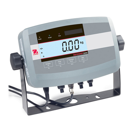
EN-6 5000 Series Indicators Overview of Parts and Controls TABLE 1-1. T51P PARTS. Item Description Data Label Front Housing Control Panel Adjusting Knob (2) Mounting Bracket Security Screw Data Label Rear Housing Battery Cover Screw (4) Power Receptacle Hole plug for option... - Page 8 5000 Series Indicators EN-7 Overview of Parts and Controls (Cont.) TABLE 1-2. T51XW PARTS. Item Description Data Label Front Housing Control Panel Adjusting Knob (2) Mounting Bracket Screw (4) Rear housing Data Label Security Screw Strain relief for option Strain relief for RS232 Strain relief for option Strain relief for option Strain relief for Load Cell...
- Page 9 Sense Jumper W1 Alternate Load Cell Terminal Block J4 Sense Jumper W2 Security Switch SW2 External input Terminal Block J9 RS232 Terminal Block J7 (T51XW only) Load Cell Connector (T51P only) GlobalTestSupply www. .com Find Quality Products Online at: sales@GlobalTestSupply.com...
- Page 10 5000 Series Indicators EN-9 Overview of Parts and Controls (Cont.) 7 8 9 Figure 1-4. Controls and Indicators. TABLE 1-4. CONTROL PANEL. Designation Designation TARE Menu button UNDER LED Pieces symbol ACCEPT LED FUNCTION Mode button OVER LED PRINT Units button Capacity Label Window ON/ZERO Off button Brackets (not used)
-
Page 11: Control Functions
EN-10 5000 Series Indicators Control Functions TABLE 1-5. CONTROL FUNCTIONS. Button ON/ZERO PRINT FUNCTION TARE Primary Function (Short Press) Turns the Indicator Sends the current value Initiates an application Performs a tare to the selected COM mode. operation. ports if AUTOPRINT is If Indicator is On, sets set to Off. -
Page 12: Installation
2.2.1 Scale Base with Connector to T51P Ohaus bases with a connector can be attached to the external load cell connector (Figure 1-1, item 14). Refer to section 2.3.2 for bases without a connector. To make the connection, plug the base connector onto the external load cell connector. Then rotate the base connector’s locking ring clockwise. -
Page 13: Mounting Bracket
The screws should be tightened to 2.5 N m (20-25 in-lb) torque to ensure a watertight seal. • Connection 2.3.2 Scale Base Without Connector to T51P or T51XW Bases without a connector must be attached to the internal load cell connector on the main J4-1 +EXE PC board. Pass the load cell cable through the strain relief (Figure 1-1, item 13 or Figure 1-2,... -
Page 14: Rs232 Interface Cable To T51Xw
The T51P is delivered in the wall mount orientation with the connections exiting below the display. The rear housing may be reversed so the connections exit above the display when the T51P is placed horizontally on a bench. To reverse the rear housing, remove the four Phillips head screws, carefully rotate the housing 180°, and reinstall the screws. -
Page 15: Settings
EN-14 5000 Series Indicators SETTINGS Menu Structure TABLE 3-1. MENU STRUCTURE. CALIBRATION SETUP READOUT MODE UNIT GMP PRINT1 • ZERO • RESET • RESET • RESET • RESET • RESET • RESET • SPAN • RANGE • STABLE RANGE • WEIGH • KILOGRAM • DATE • STABLE ONLY • LINEARITY • CAPACITY • FILTER... -
Page 16: Menu Navigation
5000 Series Indicators EN-15 Menu Navigation Enter the menu by pressing the TARE Menu button until MENU is displayed. When the button is released, the Legal for Trade status is displayed, followed by the first menu. Press the No or Back button to move to a different menu. -
Page 17: Zero Calibration
EN-16 5000 Series Indicators 3.3.1 Zero Calibration Zero calibration uses one calibration point. The zero calibration point is established with no weight on the scale. Use this calibration method to adjust for a different pre-load without affecting the span or linearity calibration. -
Page 18: Linearity Calibration
5000 Series Indicators EN-17 3.3.3 Linearity Calibration Linearity calibration uses 3 calibration points. The full calibration point is established with a weight on the scale. The mid calibration point is established with a weight equal to half of the full calibration weight on the scale. The zero calibration point is established with no weight on the scale. The mid calibration points cannot be altered by the user during the calibration procedure. -
Page 19: Calibration Test
EN-18 5000 Series Indicators 3.3.5 Calibration Test Calibration test is used to compare a known calibration weight against the stored span calibration data. NOTE: Calibration Test is always available (even when LFT is set to ON). When tESt is displayed, press the Yes button to initiate Calibration Test. The display flashes 0. With no weight on the scale, press the Yes button to record the current zero point. The display shows --t-- while the zero point is recorded. - Page 20 5000 Series Indicators EN-19 TABLE 3-2. GEOGRAPHICAL ADJUSTMENT VALUES Elevation above sea level in meters Geographical latitude 1300 1625 1950 2275 2600 2925 3250 away from the equator, 1300 1625 1950 2275 2600 2925 3250 3575 (North or South) in Elevation above sea level in feet 1060 2130 3200...
-
Page 21: Setup Menu
EN-20 5000 Series Indicators Setup Menu When the Indicator is used for the first time, enter this No, Yes Reset menu to set the Range, Capacity and Graduation. Default Range Single, Dual settings are bold. Full Scale Capacity 1…999950 0.00001…1000 Graduation Power On unit Auto, kg, g, lb, oz, lb:oz 2%, 100%... -
Page 22: Graduation
5000 Series Indicators EN-21 3.4.4 Graduation Set the scale readability. 0.00001, 0.00002, 0.00005, 0.0001, 0.0002, 0.0005, 0.001, 0.002, 0.005, 0.01, 0.02, 0.05, 0.1, 0.2, 0.5, 1, 2, 5, 10, 20, 50, 100, 200, 500, 1000. • NOTE: Graduation settings are limited to values from Capacity divided by 1000 to Capacity divided by • 30000. Therefore, not all settings are available for each capacity. •... -
Page 23: Auto-Tare
EN-22 5000 Series Indicators 3.4.7 Auto-Tare Set the Automatic Tare functionality. = Automatic Tare is disabled. = the first stable gross weight will be tared. ACCEPt = when the application mode is CHECK, stable gross weight that is within the Checkweigh accept limits will be tared. -
Page 24: Beeper Volume
5000 Series Indicators EN-23 3.4.10 Beeper Volume Set the beeper volume. = disabled. = soft = loud. 3.4.11 Beeper Signal Set how the beeper responds in the Checkweigh mode. = the beeper is disabled. ACCEPt = the beeper will sound when the weight is within the Accept range. UNdEr = the beeper will sound when the weight is below the Under setting. -
Page 25: Reset
EN-24 5000 Series Indicators 3.5.1 Reset Set the Readout menu to factory default settings. = not reset YES = reset If the Legal for Trade menu item is set to ON, the Stable Range, Averaging Level, Auto Zero Tracking, Auto Off and Gross settings are not reset. -
Page 26: Backlight
5000 Series Indicators EN-25 3.5.5 Backlight Set the display backlight functionality. = always off. = always on. AUtO = turns on when a button is pressed or the displayed weight changes. When Auto is selected, set Backlight shut off time. Settings: SEt 1 = backlight turns off after 1 minute of no activity. -
Page 27: Reset
EN-26 5000 Series Indicators 3.6.1 Reset Set the Mode menu to the factory defaults. = not reset. YES = reset. NOTE: If the Legal for trade menu item is set ON, the settings are not reset. 3.6.2 Weighing Mode Set the status. = Disabled = Enabled 3.6.3 Parts Counting Mode Set the status. = Disabled = Enabled 3.6.4 Parts Counting Optimize... -
Page 28: Check Weighing Mode
5000 Series Indicators EN-27 3.6.7 Check Weighing Mode Set the status. = Disabled = Enabled 3.6.8 End Mode Advance to the next menu. Unit Menu Enter this menu to activate the desired units. Default settings are Reset No, Yes bold. Off, On Kilograms Pounds Off, On... -
Page 29: Gram Unit
EN-28 5000 Series Indicators 3.7.4 Gram Unit Set the status. = Disabled = Enabled 3.7.5 Ounce Unit Set the status. = Disabled = Enabled NOTE: Ounce Unit is not available when Range is set to Dual. 3.7.6 Pound Ounce Unit Set the status. -
Page 30: End Unit
5000 Series Indicators EN-29 Exponent Set the factor multiplier. = 10 (Factor x 1) = 10 (Factor x 10) • = 10 (Factor x 100) • = 10 (Factor x 1000) • = 10 (Factor ÷ 100) = 10 (Factor ÷ 10) Least Significant Digit Set the custom unit readability. -
Page 31: Date Set
EN-30 5000 Series Indicators 3.8.3 Date Set Set the date. 00 to 99 = year position 01 to 12 = month position 01 to 31 = day position Refer to Section 3.2 Menu Navigation to enter settings. 3.8.4 Time Type Set the time format. -
Page 32: User Id
5000 Series Indicators EN-31 3.8.6 User ID Set the user identification. 000000 to 999999 Refer to Section 3.2 Menu Navigation to enter settings. 3.8.7 Project ID Set the Project identification. 000000 to 999999 Refer to Section 3.2 Menu Navigation to enter settings. 3.8.8 Scale ID Set the Scale identification. -
Page 33: Print1 And Print2 Menus
EN-32 5000 Series Indicators Print1 and Print2 Menus Enter this menu to define printing parameters. Default settings are bold. NOTE: The Print2 menu is only displayed if a second interface (RS232 or RS422/RS485) is installed. Reset No, Yes 3.9.1 Reset Stable Only Off, On Set the Print menu to factory defaults. Off, Auto Print = not reset. -
Page 34: Print Content Sub-Menu
5000 Series Indicators EN-33 When ON.StAb is selected, set the condition for printing, where: LOAd = prints when the load is stable and greater than zero LOAd.Zr = prints when any load is stable and equal to or greater than zero. When INtEr is selected, set the Print Interval. 1 to 3600 (seconds) 3.9.4 Print Content Sub-menu This sub-menu is used to define the content of the printed data. Result Set the status. - Page 35 EN-34 5000 Series Indicators Project ID Set the status. = Disabled. = the Project ID is printed. Scale ID Set the status. = Disabled. = the Scale ID is printed. Time Set the status. = Disabled. = the Date and Time is printed. Difference Set the status.
-
Page 36: Layout Sub-Menu
Set the format of the serial output string to a printer or computer. = use the default output format of the T51 indicator (see Section 5.2 Output Format). = use the output format of the Ohaus CD/CW-11 indicators (see respective CD-11/CW-11 user manuals). -
Page 37: Reset
EN-36 5000 Series Indicators 3.10.1 Reset Set the COM1 and COM2 menu to factory defaults. = not reset. YES = reset. 3.10.2 Baud Set the Baud rate. = 300 bps = 600 bps 1200 =1200 bps 2400 = 2400 bps 4800 = 4800 bps 9600... -
Page 38: Alternate Command Sub-Menu
5000 Series Indicators EN-37 3.10.7 Alternate Command Sub-menu Enter this sub-menu to set a different command character for the P (Print), T (Tare) and Z (Zero) commands. Alternate Print Command Set the alternate command character for Print. A to Z. Alternate Tare Set the alternate command character for Tare. -
Page 39: External Input
EN-38 5000 Series Indicators 3.11.2 External Input Set the function to be controlled by an optional external input device such as a foot switch. = disabled. tArE = Tare function. ZErO = Zero function. PrINt = Print function. FUNCt = action specific to the current application mode. = the first external input changes the state of the relay. -
Page 40: End I-O
5000 Series Indicators EN-39 Contact Set the timing of the relay contacts. = relays open or close at the same time. b-b-M = relay opens before the next relay closes (break before make). M-b-b = relay closes before the next relay opens (make before break). NOTE: A 100 ms delay or over-lap is used for the break-before-make and make-before-break timing. -
Page 41: Lock Setup
EN-40 5000 Series Indicators 3.12.3 Lock Setup Set the status. = Setup menu is not locked. = Setup menu is locked. 3.12.4 Lock Readout Set the status. = Readout menu is not locked. = Readout menu is locked. 3.12.5 Lock Mode Set the status. -
Page 42: Lock Gmp
5000 Series Indicators EN-41 3.12.11 Lock GMP Set the status. = GMP menu is not locked. = GMP menu is locked. 3.12.12 Lock I-O Set the status. = I-O menu is not locked. = I-O menu is locked. 3.12.13 End Lock Advance to the next menu. -
Page 43: Lock Print Button
EN-42 5000 Series Indicators 3.13.5 Lock Print Button Set the status. = Print button is unlocked. = Print button is locked. 3.13.6 Lock Unit Button Set the status. = Unit button is unlocked. = Unit button is locked. 3.13.7 Lock Function Button Set the status. -
Page 44: Operation
5000 Series Indicators EN-43 OPERATION Turning Indicator On/Off To turn the Indicator on, press the ON/ZERO Off button. The Indicator performs a display test followed by a series of informational displays, and then enters the active weighing mode. To turn the Indicator off, press and hold the ON/ZERO Off button until OFF is displayed. Zero Operation Zero can be set under the following conditions: • Automatically at Power On (initial zero). -
Page 45: Changing Units Of Measure
EN-44 5000 Series Indicators Changing Units of Measure Press and hold the PRINT Units button until the desired measuring unit appears. Only measuring units enabled in the Unit Menu will be displayed (refer to Section 3.7). Printing Data Printing the displayed data to a printer or sending the data to a computer requires that the communication parameters in the Print and Communication Menu are set (refer to Sections 3.9 and 3.10). Press the PRINT Units button to send the displayed data to the communication port (the Auto-Print Mode in Section 3.9 function must be Off). -
Page 46: Percent Weighing
5000 Series Indicators EN-45 Establishing a New APW Press the No button to increment the sample size. Choices are 5, 10, 20, 50 and 100. To establish the APW, place the specified quantity of samples on the scale and press the FUNCTION Mode button to capture the weight. APW is displayed shortly followed by the APW value with the current unit of measure. Begin Counting Place the parts on the scale and read the count. -
Page 47: Check Weighing
EN-46 5000 Series Indicators 4.8.4 Check Weighing Use this mode to determine if the weight of a sample is within prescribed limits. Checkweighing Limits When the FUNCTION Mode button is released, CLr.rEF is displayed. Clearing Stored Check Weighing Limits Press the Yes button to clear the stored limits. Recalling Stored Check Weighing Limits Press the No button to recall the stored limits. -
Page 48: Dynamic Weighing
5000 Series Indicators EN-47 4.8.5 Dynamic Weighing Use this mode to weigh moving or oversized objects. The weight is held on the display until reset. Manual, semi-automatic and automatic start/stop methods are available (refer to Section 3.6.6). Begin Dynamic Weighing When the display shows rEAdY, place the object on the scale. -
Page 49: Serial Communication
EN-48 5000 Series Indicators SERIAL COMMUNICATION The T51P and T51XW Indicators include an RS232 serial communication interface. The setup of RS232 operating parameters are more fully explained in Section 3.10. The physical hardware connection is explained in Section 2.6. The interface enables display and GMP data to be sent to a computer or printer. A computer can be used to control some functions of the indicator using the commands listed in Table 5-1. -
Page 50: Output Format
5000 Series Indicators EN-49 Output Format The default serial output format is shown below. Field: Weight Space* Unit Space* Stability Space* Space* Term. Char(s) Length: *Each field is followed by a single delimiting space (ASCII: 32) Definitions: Weight - up to 9 characters, right justified, “-” at immediate left of most significant character (if negative). Unit - The Unit field contains the unit of measure abbrevation in 5 characters, left justified. - Page 51 EN-50 5000 Series Indicators Dynamic Mode Printout Check Weighing Mode Printout Calibration Test Printout O h a u s C o r p o r a t i o n O h a u s C o r p o r a t i o n - - - - - - - - - C a l T e s t - - - - - - - - - 1 9 A C h a p i n...
-
Page 52: Legal For Trade
The local weights and measures official or authorized service agent must apply a security seal to prevent tampering with the settings. Refer to the illustrations below for sealing methods. Figure 6-1. T51P Wire Seal Figure 6-2. T51XW Wire Seal GlobalTestSupply www. - Page 53 EN-52 5000 Series Indicators SEAL Figure 6-3. T51P Paper Seal Figure 6-4. T51XW Paper Seal When the scale base is attached to the indicator using a connector, it is necessary to seal the load cell cable to the indicator in some jurisdictions.
-
Page 54: Maintenance
5000 Series Indicators EN-53 MAINTENANCE CAUTION: DISCONNECT THE UNIT FROM THE POWER SUPPLY BEFORE CLEANING. Model T51P Cleaning • The housing may be cleaned with a cloth dampened with a mild detergent if necessary. • Do not use solvents, chemicals, alcohol, ammonia or abrasives to clean the housing or control panel. Model T51XW Cleaning • Use approved cleaning solutions for the stainless-steel Indicator housing and rinse with water. Dry thoroughly. • Do not use solvents, chemicals, alcohol, ammonia or abrasives to clean the control panel. Troubleshooting TABLE 7-1. TROUBLESHOOTING. SYMPTOM PROBABLE CAUSE(s) REMEDY Unit will not turn on. Power cord not plugged in or properly Check power cord connections. -
Page 55: Service Information
If the troubleshooting section does not resolve your problem, contact an authorized Ohaus Service Agent. For Service assistance in the United States, call toll-free 1-800-526-0659 between 8:00 AM and 5:00 PM Eastern Standard Time. An Ohaus Product Service Specialist will be available to assist you. Outside the USA, please visit our website www.ohaus.com to locate the Ohaus office nearest you. -
Page 56: Technical Data
2.3 / 5 4.3 / 9.5 Operating Temperature Range -10°C to 40°C/14°F to 104°F 100-240 VAC / 50-60 Hz Internal Universal Power Supply, Power 6 C-type batteries (T51P) Interface Built-in RS232 and External Input GlobalTestSupply www. .com Find Quality Products Online at:... -
Page 57: Accessories And Options
Accessories and Options TABLE 8-2. OPTIONS. DESCRIPTION PART NUMBER AC Relay Kit 80500720 Base Mount Kit , T51P 80500722 Column Mount Kit, 35 cm painted steel 80500723 Column Mount Kit, 68 cm painted steel 80500724 Column Mount Kit, 35 cm stainless steel... -
Page 58: Drawings And Dimensions
5000 Series Indicators EN-57 Drawings and Dimensions Figure 8-1. T51P Indicator Overall Dimensions with Mounting Bracket. Figure 8-2. T51XW Indicator Overall Dimensions with Mounting Bracket. GlobalTestSupply www. .com Find Quality Products Online at: sales@GlobalTestSupply.com... -
Page 59: Compliance
Marking Standard This product conforms to the EMC Directive 2004/108/EC, the Low Voltage Directive 2006/95/EC and the Non-automatic Weighing Instruments Directive 2009/23/EC. The complete Declaration of Conformity is available online at www.ohaus.com. UL60950-1: 2003 AS/NZS4251.1, AS/NZS4252.1 EU Emissions Note This device complies with EN55011 / CISPR 11 Class A Group 1. - Page 60 Should this device be passed on to other parties (for private or professional use), the content of this regulation must also be related. For disposal instructions in Europe, refer to www.ohaus.com, choose your country then search for WEEE. Thank you for your contribution to environmental protection.
- Page 61 Ohaus. In lieu of a properly returned warranty registration card, the warranty period shall begin on the date of shipment to the authorized dealer.
Need help?
Do you have a question about the T51P and is the answer not in the manual?
Questions and answers