Table of Contents
Advertisement
Available languages
Available languages
Advertisement
Table of Contents

Related Manuals for OHAUS DEFENDER 7000 XtremeW Series


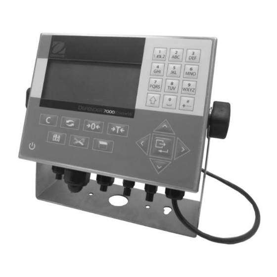
Summary of Contents for OHAUS DEFENDER 7000 XtremeW Series
- Page 1 7000 Series Indicators User Guide...
- Page 2 EN-2 2000 SERIES INDICATORS...
-
Page 3: Safety Information
Use the instrument exclusively for weighing as described in the operating instructions. Any other type of use and operation beyond the limits of technical specifications without written consent from OHAUS, is considered as not intended. This instrument complies with current industry standards and the recognized safety regulations; however, it can constitute a hazard in use. -
Page 4: Scale Bases
EN-2 7000 SERIES INDICATORS An SD memory card socket is mounted to the PCB to support the optional SD memory and bus connectors are included for the option boards. 2.2 Scale Bases The T72XW terminal supports analog scale bases and provides 10 volts of excitation to drive analog load cells. Up to ten 350Ω... - Page 5 EN-3 2.5.1 Main Board Wiring Connections Once the T72XW terminal harsh enclosure is open, connections can be made to the terminal strips on the main board, as shown below. Load cell connector power connector Option 1 connector switches Option 2 connector T72XW Main Board Connections, AC Model 2.5.2 Analog Load Cell Connections...
- Page 6 EN-4 7000 SERIES INDICATORS Recommended Maximum Cable Lengths 24 Gauge TSR (Ohms) 20 Gauge (meters/feet) 16 Gauge (meters/feet) (meters/feet) 243/800 610/2000 1219/4000 87 (4-350 cells) 60/200 182/600 304/1000 43 (8-350 cells) 30/100 91/300 152/500 35 (10-350 cells) 24/80 60/200 120/400...
-
Page 7: Closing The Enclosure
EN-5 An example of connecting via RS-232 to external equipment is shown below. Make the connections as necessary. NOTES: 1. USE ONLY SHIELDED CABLE. 2. MAXIMUM CABLE LENGTH: 50 FEET (15 METERS). 3. WIRE SIZE: 18 AWG (.823 mm ) MAXIMUM 24 AWG (0.205 mm ) MINIMUM. - Page 8 EN-6 7000 SERIES INDICATORS CLEAR When in the net weight mode, press CLEAR to clear the current tare value; the display will revert to the gross weight value. CLEAR operates regardless of motion on the scale. Note that once the tare value has been cleared, it cannot be recalled.
-
Page 9: Menu Structure
EN-7 The symbols that may appear on the display are described in the table bel Symbol Explanation I/O status* (On and Off) 2 inputs, 4 outputs = Input or output active Time and date* Numeric, Upper case alpha, lower case alpha and Decimal data entry mode. -
Page 10: Maintenance
The exterior surfaces of the instrument may be cleaned with a cloth dampened with water and a mild detergent. 4.2 Troubleshooting For technical issues contact an Authorized Ohaus Service Agent. Please visit our website www.ohaus.com to locate the Ohaus office nearest you. -
Page 11: Información Sobre Seguridad
Este equipo cumple con los estándares de la industria y las normas actuales de seguridad reconocidas; sin embargo, puede constituir un peligro en su uso. Si el equipo no se utiliza de acuerdo al manual de instrucciones, su seguridad puede verse afectada, por lo que OHAUS no asume ninguna responsabilidad. -
Page 12: Apertura De La Caja
ES-2 INDICADORES SERIE 7000 La tarjeta principal también contiene la conexión de entrada de energí a, la interfaz de pantalla, la interfaz de teclado y un interruptor a DIP de seis posiciones. Un puerto para tarjetas de memoria SD está instalado en la tarjeta de circuito impreso respaldar la memoria SD opcional y se incluyen conectores de enlace de comunicaciones para las tarjetas opcionales. - Page 13 ES-3 2.5.1 Conexión para cables de la tarjeta principal Una vez que la caja para ambientes adversos del terminal T72XW esté abierta, las conexiones podrán hacerse en las tablillas de terminales de la tarjeta principal, tal y como se muestra a continuación. Conector Conector de la...
- Page 14 ES-4 INDICADORES SERIE 7000 Longitudes máximas recomendadas para cables Calibre 24 TSR (ohmios) Calibre 20 (metros/pies) Calibre 16 (metros/pies) (metros/pies) 243/800 610/2000 1219/4000 87 (cé lulas 4-350 ) 60/200 182/600 304/1000 43 (cé lulas 8-350 ) 30/100 91/300 152/500 35 (cé lulas 10-350 ) 24/80 60/200 120/400...
- Page 15 ES-5 A continuación se muestra un ejemplo de conexión a través del RS-232 con equipos externos. Realice las conexiones según sea necesario. NOTAS: 1. UTILICE Ú NICAMENTE UN CABLE BLINDADO. 2. LONGITUD MÁXIMA DEL CABLE: 50 PIES (15 METROS). 3. TAMAÑO DEL CABLE: 18 AWG (.823 mm ) MÁXIMO 24 AWG (0.205 mm ) MÍ...
- Page 16 ES-6 INDICADORES SERIE 7000 BORRAR Con el modo de peso neto, presione CLEAR para borrar el valor de tara actual; la pantalla regresará al valor de peso bruto. CLEAR funciona independientemente del movimiento sobre la báscula. Observe que una vez que se haya borrado el valor de tara, ya no se puede recuperar. Debe realizarse el proceso completo de tara, tal como se ha descrito anteriormente.
-
Page 17: Estructura Del Menú
ES-7 Los sí mbolos que pueden aparecer en la pantalla de describen en la tabla indicada a continuació n. Sí mbolo Explicación Estado I/O* (Encendido y Apagado) 2 entradas, 4 salidas = Entrada o salida activa Fecha y hora* Modo de entrada de datos numéricos, alfanuméricos con mayúsculas, alfanuméricos con minúsculas y decimales. -
Page 18: Mantenimiento
Para la superficie exterior del dispositivo puede utilizar un paño ligeramente humedecido con agua o un detergente suave. 4.2 Solución de problemas Para cuestiones técnicas póngase en contacto con un agente de servicio autorizado de Ohaus. Por favor, visite nuestra página web www.ohaus.com para localizar la oficina de Ohaus más cercana a usted. -
Page 19: Informations De Securite
écrit de la société OHAUS sera considéré comme non conforme. Cet appareil est conforme aux normes industrielles et aux règles de sécurité en vigueur ; cependant, son utilisation peut engendrer un risque de danger. -
Page 20: Ouverture Du Boî Tier
FR-2 LES INDICATEURS 7000 La carte principale est également dotée d'un raccord entrée alimentation, d'une interface pour l'écran d'affichage, d'une interface pour le clavier et d'un commutateur DIP à six positions. Un logement pour la carte mémoire SD est installé sur la carte PCprincipale pour prendre en charge la mémoire SD optionnelle, et les connecteurs bus sont fournis pour les cartes en option. - Page 21 FR-1 2.5.1 Raccordements sur la carte principale Après l'ouverture du boî tier dur du terminal T72XW, il est possible de relier les fils aux barrettes de raccordement sur la carte principale, comme présenté ci-après. Raccord de Raccord la cellule de pesée l'alimentati on CA...
- Page 22 FR-4 LES INDICATEURS 7000 Les longueurs de câble maximales recommandées Section 24 TSR (Ohms) Section 20 (mètres/pieds) Section 16 (mètres/pieds) (mètres/pieds) 243/800 610/2000 1219/4000 87 (4-350 cellules) 60/200 182/600 304/1000 43 (8-350 cellules) 30/100 91/300 152/500 35 (10-350 cellules) 24/80 60/200 120/400...
-
Page 23: Fermeture Du Boî Tier
FR-1 Voici un exemple de raccordement du matériel externe à l’aide de RS-232. Procé der aux raccordements au besoin. NOTES : 1. N'UTILISER QU'UN CABLE BLINDE. 2. LA LONGUEUR MAXIMALE DE CABLE : 50 PIEDS (15 METRES). 3. DIMENSION DU FILS : 18 AWG (.823 mm ) MAXIMUM 24 AWG (0.205 mm ) MINIMUM. - Page 24 FR-6 LES INDICATEURS 7000 CLEAR Dans le mode du poids net, appuyer sur CLEAR pour effacer la valeur courante de la tare ; l'écran affichera la valeur du poids brut. CLEAR fonctionne indépendamment du mouvement sur la balance. N.B.: après effaç age de la valeur de la tare, il ne sera plus possible d'y revenir. Le processus de tarage complet doit être exécuté, comme susvisé.
-
Page 25: Structure Du Menu
FR-1 Les symboles pouvant être affichés sont décrits dans le tableau ci-après. Symbole Explication Statut I/O* (allumé ou éteint) 2 entré es, 4 sorties = entrée ou sortie active L'heure et la date* Mode de saisie numérique, majuscule, minuscule et décimale. Mode de saisie décimale est uniquement disponible sur les écrans de saisie de formulaires en chaî... -
Page 26: Entretien
Le boî tier peut être nettoyé avec un chiffon humide et un détergent doux. 4.2 Dépannage Pour les questions techniques, contacter un réparateur agréé Ohaus. Visiter notre site Web www.ohaus.com pour trouver le bureau Ohaus le plus proche de vous. - Page 27 Verwenden Sie das Gerät ausschließlich für Wiegen entsprechend der Beschreibung in der Bedienungsanleitung. Jede andere Art von Nutzung und Betrieb außerhalb der technischen Spezifikationsgrenzen wird, ohne schriftliche Zustimmung von OHAUS, als nicht bestimmungsgemäßer Gebrauch angesehen. Dieses Gerät entspricht den aktuellen Industriestandards und den anerkannten Sicherheitsregeln, es kann aber eine Gefahr im Einsatz darstellen.
-
Page 28: Gehäuse Öffnen
DE-2 INDIKATOREN DER 7000 SERIE Die Hauptplatine verfügt zusätzlich ü ber Netzanschluss, Anzeigerschnittstelle, Tastaturschnittselle und einen 6-fachen DIP- Schalter. In die Hauptplatine wurde auch eine SD-Kartenslot eingebaut um optionale SD-Speicher; der Busstecker ist für Optionsplatinen gedacht. 2.2 Wä gebrücken Das T72XW-Terminal unterstützt analoge Wä gebrücken und gibt 10 Volts Erregung für Antrieb der analogen Wä gezellen. Das Terminal kann bis zu zehn 350Ω... - Page 29 DE-3 2.5.1 Drahtverbindungen der Hauptplatine Nach dem Öffnen des Gehä uses von T72XW Terminal, können die Verbindungen zu den Klemmleisten des Terminals auf der Hauptplatine hergestellt werden, entsprechend der nachfolgenden Abbildung. Wä gezellen Stromans anschluss chluss Option 1 Anschluss buchse Schalter Option 2 Anschlus...
- Page 30 DE-4 INDIKATOREN DER 7000 SERIE Empfohlene maximale Kabellänge 24 Querschnitt TSR (Ohm) 20 Querschnitt (Meter/Fuß) 16 Querschnitt (Meter/Fuß) (Meter/Fuß) 243/800 610/2000 1219/4000 87 (4-350 Zellen) 60/200 182/600 304/1000 43 (8-350 Zellen) 30/100 91/300 152/500 35 (10-350 Zellen) 24/80 60/200 120/400...
-
Page 31: Gehäuse Schließen
DE-5 Ein Beispiel des Anschlusses über RS-232 mit externem Zubehör ist unten angezeigt. Führen Sie die Verbindung entsprechend den Bedürfnissen aus. ANMERKUNG: 1. BENUTZEN SIE AUSSCHLIESSLICH ABGESCHIRMTE KABEL. 2. MAXIMALE KABELLÄNGE: 50 FUSS (15 METER). 3. DRAHTGRÖ SSE: 18 AWG (.823 mm ) MAXIMUM 24 AWG (0.205 mm ) MINIMUM. - Page 32 DE-6 INDIKATOREN DER 7000 SERIE CLEAR Wenn im Nettogewichtsmodus, drücken Sie CLEAR um die aktuellen Tarawerte zu löschen; der (Löschen) Anzeiger wird zum Bruttogewichtswert zurückkehren. CLEAR arbeitet unabhängig von der Bewegung auf der Waage. Bemerken Sie, dass die Tarawerte nach dem Löschen nicht wieder abgerufen werden.
- Page 33 DE-7 Symbole, die auf dem Anzeiger erscheinen kö nnen, sind in der nachstehenden Tabelle erlä utert Symbol Erläuterung I/O status* ((Ein und Aus)) 2 Eingä nge, 4 Ausgänge = Input or output active Zeit und Datum* Dateneingabe: nummerisch, Großschreibung Alpha, Kleinschreibung Alpha, dezimal. Dezimalmodus ist nur auf Bildschirmmasken mit Zeichenketten verfügbar Taratyp- und Wertangabe...
-
Page 34: Wartung
Die Gehäuseflächen dü rfen mit einem fusselfreien, leicht mit Wasser oder einer milden Reinigungslösung geträ nktes Tuch gereinigt werden. 4.2 Fehlerbehebung Bei technischen Fragen wenden Sie sich an den autorisierten Ohaus Service Agenten. Besuchen Sie unsere Webseite unter www.ohaus.com, um eine Ohaus-Niederlassung in Ihrer Nähe zu finden. 5. TECHNISCHE DATEN Betriebsumgebung Das Terminal kann in Temperaturbereichen von 10°... -
Page 35: Informazioni Sulla Sicurezza
Questo strumento è conforme agli standard industriali attuali e alle norme di sicurezza riconosciute; tuttavia, può costituire un pericolo durante l’uso. OHAUS non si assume alcuna responsabilità per l'uso dello strumento non conforme alle presenti istruzioni che può comprometterne la sicurezza. - Page 36 IT-2 INDICATORI SERIE 7000 La scheda madre è dotata anche di uno slot per la scheda di memoria SD opzionale e di connettori bus per le schede opzionali. 2.2 Basi per le bilance Il terminale T72XW supporta le basi per bilance analogiche e fornisce un'eccitazione di 10 V per alimentare le celle di carico analogiche.
- Page 37 IT-3 2.5.1 Collegamenti cablaggio scheda madre Dopo aver aperto l'involucro rigido del terminale T72XW è possibile effettuare le connessioni ai morsetti del terminale sulla scheda madre, come illustrato sotto. Connettore Connettore di della cella di alimentazione carico Connettore opzione 1 Interruttori Connettore opzione 2...
- Page 38 IT-4 INDICATORI SERIE 7000 Lunghezza massima del cavo raccomandata: TSR (ohm) Misura 24 (metri/piedi) Misura 20 (metri/piedi) Misura 16 (metri/piedi) 243/800 610/2000 1219/4000 87 (4-350 celle) 60/200 182/600 304/1000 43 (8-350 celle) 30/100 91/300 152/500 35 (10-350 celle) 24/80 60/200 120/400...
-
Page 39: Funzionamento
IT-5 Nella figura sottostante è mostrato un esempio di connessione mediante RS-232 di apparecchiature esterne. Effettuare le connessioni secondo quanto richiesto. NOTE: 1. UTILIZZARE SOLO UN CAVO SCHERMATO. 2. LUNGHEZZA MASSIMO DEL CAVO: 15 METRI. 3. DIAMETRO FILO: 18 AWG (0,823 mm ) MASSIMO 24 AWG (0,205 mm ) MINIMO. - Page 40 IT-6 INDICATORI SERIE 7000 CANCELLA In modalità di peso netto, premere CANCELLA per eliminare il valore corrente di tara; il display visualizzerà nuovamente il valore di peso lordo. Il funzionamento del tasto CANCELLA è indipendente dal movimento della bilancia. Tenere presente che una volta cancellato, il valore della tara non può...
-
Page 41: Struttura Del Menu
IT-7 I simboli che possono apparire sul display sono descritti nella tabella Simbolo Significato Stato I/O* (On e Off) 2 ingressi, 4 uscite = ingresso o uscita attiva Ora e data* Modalità inserimento dati numerici, alfabetici in maiuscolo, alfabetici in minuscolo e decimali. La modalità... -
Page 42: Manutenzione
Sulle superfici dell’apparecchio può essere utilizzato un panno leggermente inumidito con acqua o con un detergente delicato. 4.2 Risoluzione dei problemi Per problemi tecnici contattare un agente di manutenzione Ohaus autorizzato. Si prega di visitare il nostro sito web www.ohaus.com per individuare l'ufficio Ohaus più vicino. -
Page 43: Informações De Segurança
Se o instrumento não for utilizado de acordo com estas instruç ões de funcionamento, a proteç ão pretendida do instrumento pode ficar comprometida e a OHAUS não assume qualquer responsabilidade. QUANDO ESTE EQUIPAMENTO É INCLUÍ DO COMO UM COMPONENTE PARTE DO SISTEMA, O DESIGN RESULTANTE DEVE SER ANALISADO POR PESSOAL QUALIFICADO QUE ESTEJA FAMILIARIZADO COM A CONSTRUÇÃO E FUNCIONAMENTO DE TODOS OS COMPONENTES NO... -
Page 44: Bases Da Balança
PT-2 INDICADORES DA SÉRIE 7000 A placa principal também contém a ligaç ã o de entrada da alimentaç ão, interface de exibiç ão, interface do teclado e comutador DIP de seis posiç ões. Encontra-se montada uma ranhura para cartõ es de memória SD na PCB para suportar memória SD opcional e os conectores de barramento são incluí... - Page 45 PT-3 2.5.1 Ligaç ões da placa principal Assim que a caixa de proteç ão resistente do terminal T72XW estiver aberta, é possí vel efetuar as ligaç õ es aos bornes de ligaç ã o na placa principal, conforme mostrado abaixo. Conector da Conector célula de carga...
- Page 46 PT-4 INDICADORES DA SÉRIE 7000 Comprimentos máximos recomendados de cabo Espessura 24 TSR (Ohms) Espessura 20 (metros/pés) Espessura 16 (metros/pés) (metros/pés) 243/800 610/2000 1219/4000 87 (4-350 cé lulas) 60/200 182/600 304/1000 43 (8-350 cé lulas) 30/100 91/300 152/500 35 (10-350 ...
- Page 47 PT-5 É exibido abaixo um exemplo de ligaç ão por RS-232 a equipamento externo. Efetue as ligaç ões necessá rias. NOTAS: 1. UTILIZE APENAS UM CABO BLINDADO. 2. COMPRIMENTO MÁXIMO DO CABO: 50 PÉS (15 METROS). 3. DIMENSÃO DO FIO: MÁXIMO 18 AWG (0,823 mm MÍ...
- Page 48 PT-6 INDICADORES DA SÉRIE 7000 APAGAR Quando em modo de peso lí quido, prima APAGAR para limpar o valor de tara atual; o ecrã irá reverter para o valor de peso bruto. APAGAR funciona independentemente do movimento da balanç a. Note que assim que o valor de tara tiver sido apagado, não pode ser reposto. Deve ser realizado o processo completo de tara, conforme descrito acima.
-
Page 49: Estrutura Do Menu
PT-7 Os sí mbolos que podem aparecer no ecrã estão descritos na tabela abaixo: Sí mbolo Explicaç ão Estado da E/S* (Ligado e Desligado) 2 entradas, 4 saí das = entrada ou saí da ativa Hora e data* Modo de introduç ão numérica, alfa maiúsculas e minúsculas, decimais. -
Page 50: Dados Técnicos
As superfí cies exteriores do instrumento podem ser limpas com um pano humedecido com água e um detergente neutro. 4.2 Resolução de problemas Para problemas técnicos, entre em contacto com um agente de serviç o autorizado da Ohaus. Visite o nosso site Web www.ohaus.com para localizar o estabelecimento Ohaus mais próximo de si. -
Page 51: Installation
Detta instrument uppfyller gä llande branschstandarder och erkända säkerhetsbestämmelser; men det kan utgö ra en fara i bruk. Om instrumentet inte används i enlighet med dessa användarinstruktioner, kan skydd av instrumentet försämras och OHAUS tar inget ansvar. När denna utrustning ingår som en beståndsdel i ett system, skall den resulterande designen ses över av kvalificerad personal som är förtrogna med konstruktion och drift av alla komponenter i systemet och de... - Page 52 SV-2 7000 SERIES INDIKATORER En SD-minneskorts sockel är monterad på kretskortet fö r att stödja de valfria SD-minneskort och bussanslutningar som ingår för tillvalskorten. 2.2 Vågbaser T72XW terminalen stö der analoga vå gbaser och tillhandahå ller 10 volt excitation för att driva analoga lastceller. Upp till tio 350Ω...
- Page 53 SV-3 2.5.1 Tråd Anslutningar på det Huvudsakliga Kretskortet När T72XW terminalens inre hårda hö lje är öppet så kan anslutningar gö ras till terminal plintarna på det huvudsakliga kretskortet enligt nedan. Lastcells anslutning Strö m anslutning Val 1 anslutning omkopplare Val 2 anslutning T72XW Huvudsakliga Kretskort Anslutningar, AC Modell...
- Page 54 SV-4 7000 SERIES INDIKATORER Rekommenderade Maximala Kabel Lä ngder TSR (Ohms) 24 Mätare (meter/fot) 20 Mätare (meter/fot) 16 Mätare (meter/fot) 243/800 610/2000 1219/4000 87 (4-350 celler) 60/200 182/600 304/1000 43 (8-350 celler) 30/100 91/300 152/500 35 (10-350 celler) 24/80 60/200 120/400...
- Page 55 SV-5 Ett exempel på anslutning via RS-232 till extern utrustning visas nedan. Gö r anslutningarna som behövs. NOTERINGAR: 1. ANVÄND ENDAST SKYDDAD KABEL 2. MAXIMAL KABEL LÄNGD CABLE LENGTH: 15 METERS 3. TRÅD STORLEK: 18 AWG (.823 mm ) MAXIMUM 24 AWG (0.205 mm ) MINIMUM.
- Page 56 SV-6 7000 SERIES INDIKATORER CLEAR När du ä r i nettovikt läget, tryck på CLEAR för att rensa aktuella tarevä rdet; displayen kommer att återgå till bruttoviktvärdet. CLEAR fungerar oavsett rö relse på vågen. Notera att nä r tarevärdet har raderats så kan det inte återkallas. Den kompletta tare process som beskrivs ovan måste utföras.
- Page 57 SV-7 The symbols that may appear on the display are described in the table bel Symbol Förklaring I/O status* (På och Av) 2 ingångar, 4 utgångar = In- eller utgångs aktiv Tid och Datum* Numeriska, Versaler alfa, gemener alfa och Decimal datainmatnings läge.
-
Page 58: Teknisk Data
De yttre ytorna på instrumentet kan rengö ras med en fuktig trasa med vatten och ett milt rengöringsmedel. 4.2 Felsökning För tekniska problem kontakta en godkänd OHAUS service agent. För tekniska frå gor kontakta ett auktoriserat OHAUS serviceombud. Besök gärna vå r hemsida www.ohaus.com för att hitta OHAUS kontoret nä rmast dig. - Page 59 Tilsigtet brug Brug udelukkende instrumentet til<vejning/fugtbestemmelse/etc.>som beskrevet i brugsanvisningen. Enhver anden form for brug og drift, der går ud over græ nserne i de tekniske specifikationer, uden skriftligt samtykke fra OHAUS, betragtes som utilsigtet. Dette instrument er i overensstemmelse med gæ ldende industristandarder og anerkendte sikkerhedsforskrifter; dog kan det udgøre en fare under brug.
- Page 60 DA-2 7000-SERIEN INDIKATORER Det primæ re printkort indeholder også strømstik, interface, displayinterface og en DIP-switch med 6 positioner. Et stik til SD-hukommelseskort er monteret på printkortet, for at understøtte den valgfri SD-hukommelse og busforbindelser er inkluderet på de valgfrie kort. 2.2 Væ...
- Page 61 DA-3 2.5.1 Hovedkortets kabelstik Når T72XWterminalens ydre kabinet er åbent, kan der oprettes forbindelser til terminalens strips på hovedkortet, som vist nedenfor Belastnings celle stik strømstik Ekstraudsty r 1 stik switches Ekstraudsty r 2 stik T72XW Hovedkort-stik, AC-model 2.5.2 Analog belastningscelles forbindelser ADVARSEL! FOR AT UNDGÅ...
- Page 62 DA-4 7000-SERIEN INDIKATORER Anbefalede maksimale kabellæ ngder TSR (ohm) Str. 24 (meter/fod) Str. 20 (meter/fod) Str. 16 (meter/fod) 243/800 610/2000 1219/4000 87 (4-350 cells) 60/200 182/600 304/1000 43 (8-350 cells) 30/100 91/300 152/500 35 (10-350 cells) 24/80 60/200 120/400 T72XW terminalen er designet til at understøtte både 2mV/V og 3mV/V belastningsceller fra den samme kredsløb.
- Page 63 DA-5 Et eksempel på tilslutning via RS-232 til eksternt udstyr er vist nedenfor. Foretag de nødvendige tilslutninger. NOTER: 1. BRUG KUN SKÆ RMET KABEL. 2. MAKSIMAL KABELLÆ NGDE: 15 METER (50 FOD). 3. KABELSTØ RRELSE: 18 GNS (.823 mm ) MAKSIMUM 24 GNS (0.205 mm ) MINIMUM.
- Page 64 DA-6 7000-SERIEN INDIKATORER SLET I nettovæ gt-tilstand, tryk da på CLEAR for at slette den aktuelle Tara-væ rdi. Displayet vender så tilbage til bruttovæ gtvæ rdien. CLEAR fungerer, uanset om der er bevæ gelse på væ gten. Bemæ rk, at når tara-væ rdien er blevet slettet, kan den ikke genskabes. Den komplette tara- proces, som beskrevet ovenfor, skal udføres.
- Page 65 DA-7 De symboler, der kan vises på displayet, er beskrevet i tabellen nedenfor Symbol Forklaring I/O status* (tæ nd og sluk) 2 indgange, 4 udgange = Indgang eller udgang aktiv Tid og dato* Indtastningstilstand; Numerisk, store alfa- bogstaver, små alfa-bogstaver og decimaldata. Decimaltilstand er kun tilgæ...
-
Page 66: Tekniske Data
Instrumentets udvendige flader kan rengøres med en klud fugtet med vand og et mildt rengøringsmiddel. 4.2 Fejlfinding Kontakt en autoriseret Ohaus servicetekniker mht. tekniske spørgsmål. Besøg vores hjemmeside www.ohaus.com, for at finde det Ohaus kontor, som er tæ ttest på dig.. -
Page 67: Środki Bezpieczeństwa
Używaj tego urządzenia jedynie w celach opisanych w instrukcji. Każde użycie inne niż jest to opisane w instrukcji i opisie technicznym bez pisemnej zgody firmy OHAUS będzie uznawane jako użycie niezgodne z przeznaczeniem. Niniejszy instrument jest zgodny z obecnymi normami branżowymi I przepisami bezpieczeństwa; jednakże może stanowić... -
Page 68: Otwieranie Obudowy
WSKAŹNIKI SERII 7000 PL-2 Obwód drukowany obejmuje również wtyk zasilania, interfejs wyświetlacza, interfejs klawiatury oraz sześć pozycyjnych przełączników DIP. Obwód drukowany posiada także wejście dla karty SD w celu umożliwienia obsługi opcjonalnych kart pamięci SD, jak również posiada złącza magistrali uwzględnione na potrzeby obsługi kart opcjonalnych. 2.2 Platforma wagi Terminal T72XW obsługuje platformy wag analogowych oraz dostarcza 10V na potrzeby pobudzenia analogowych ogniw obciążnikowych. - Page 69 PL-3 2.5.1 Złącza głównego obwodu drukowanego Po otwarciu odpornej na trudne warunki otoczenia obudowy terminala T72XW można wykonać stosowne połączenia do listw zaciskowych znajdujących się na obwodzie drukowanym, tak jak to przedstawiono poniżej. Złącze ogniwa Złącze obciążnikowego zasilania Opcjonalne złącze 1 Przełączniki DIP Opcjonalne złącze 2...
- Page 70 WSKAŹNIKI SERII 7000 PL-4 Zalecane długości maksymalne przewodów Przekrój 24 TSR (om) Przekrój 20 (metry/stopy) Przekrój 16 (metry/stopy) (metry/stopy) 243/800 610/2000 1219/4000 87 (ogniwa 4-350 ) 60/200 182/600 304/1000 43 (ogniwa 8-350 ) 30/100 91/300 152/500 35 (ogniwa 10-350 ) 24/80 60/200 120/400...
- Page 71 PL-5 Poniżej przedstawiono przykład podłączenia urządzeń zewnętrznych za pomocą portu RS-232. Wykonaj stosowne połączenia. UWAGI: 1. NALEŻY STOSOWAĆ WYŁĄCZNIE PRZEWÓD EKRANOWANY. 2. MAKSYMALNA DŁUGOŚĆ PRZEWODU: 50 STÓP (15 METRÓ W) 3. PRZEKRÓ J PRZEWODU: MAX. 18 AWG (.823 mm MIN. 24 AWG (0.205 mm Przykład połączenia portu COM1 2.6 Zamykanie obudowy Po wykonaniu wszystkich stosownych czynności wewnątrz terminala należy zatrzasnąć...
- Page 72 WSKAŹNIKI SERII 7000 PL-6 W trybie ważenia netto naciśnij CLEAR, aby usunąć aktualnie wyświetlaną wartość tary; CLEAR wyświetlacz powróci do wartości masy brutto. Funkcja CLEAR dostępna jest niezależnie od ewentualnego ruchu na powierzchni wagi. Po usunięciu wartości tary nie można jej już przywołać na wyświetlaczu.
-
Page 73: Struktura Menu
PL-7 Symbole mogące pojawić się na wyświetlaczu zostały opisane w poniższej tabeli. Objaśnienie Symbol Status I/O* (Włączony/Wyłączony) 2 wejścia, 4 wyjścia = Aktywne wejście lub wyjście Data i godzina* Tryb wprowadzania danych numerycznych, alfanumerycznych (małe i wielkie litery) oraz liczb dziesiętnych. -
Page 74: Rozwiązywanie Problemów
Powierzchnia obudowy może być czyszczona szmatką lekko zwilżoną wodą lub delikatnym środkiem czyszczącym. 4.2 Rozwiązywanie problemów W celu rozwiązania problemów technicznych skontaktuj się z autoryzowanym dealerem OHAUS. Odwiedź naszą stronę internetową www.ohaus.com w celu znalezienia biura OHAUS w Twojej okolicy. - Page 75 Als het toestel niet volgens deze gebruiksaanwijzing wordt gebruikt, kan de beoogde bescherming van het toestel worden aangetast en OHAUS aanvaardt geen enkele aansprakelijkheid hieromtrent. WANNEER DEZE APPARATUUR WORDT OPGENOMEN ALS EEN ONDERDEEL VAN EEN SYSTEEM,...
-
Page 76: De Behuizing Openen
NL-2 7000-INDICATORSERIE Het moederbord bevat ook de stroomtoevoeraansluiting, display-interface, toetsenbordinterface en DIP-schakelaars met zes posities. Een SD-geheugenkaartsleuf die aan de PCB wordt bevestigd om de optionele SD-geheugenkaart- en busconnectoren te ondersteunen die bij deze optieborden worden meegeleverd. 2.2 Weegschaalbasissen De T72XW-terminal ondersteunt analage weegschaalbasissen en voorziet 10 volt excitatiespanning om de analoge laadcellen te voeden. - Page 77 NL-3 2.5.1 Bedradingsaansluitingen van het moederbord Wanneer de behuizing van de terminal T72XW is geopend, kunnen er aansluitingen worden gemaakt met de klemmenstrook op het moederbord zoals hieronder wordt weergegeven. Laadcelcon Netstroom nector connector Optie 1 connector DIP- schakelaars Optie 2 connector Aansluitingen moederbord T72XW, wisselstroommodel 2.5.2 Aansluitingen analoge laadcel...
- Page 78 NL-4 7000-INDICATORSERIE Aanbevolen maximale kabellengten TSR (Ohm) 24 (meters/voet) 20 (meters/voet) 16 (meters/voet) 243/800 610/2000 1219/4000 87 (4-350 cellen) 60/200 182/600 304/1000 43 (8-350 cellen) 30/100 91/300 152/500 35 (10-350 cellen) 24/80 60/200 120/400 De T72XW-terminal is ontworpen om laadcellen van 2 mV/V en 3 mV/V van dezelfde schakeling te ondersteunen. Een draadbrug voor het uitgangsvermogen van de laadcel is niet vereist.
- Page 79 NL-5 Een voorbeeld van een aansluiting via een RS-232 naar externe apparatuur wordt hieronder weergegeven Maak de nodige aansluitingen OPMERKINGEN: 1. GEBRUIK ALLEEN AFGESCHERMDE KABEL. 2. MAXIMALE KABELLENGTE: 15 METER (50 VOET). 3. DRAADDIKTE: MAXIMUM 18 AWG (.823 mm MINIMUM 24 AWG (0.205 mm Voorbeeld van COM1-aansluitingen 2.6 Closing the Enclosure After all work has been completed inside the terminal, the enclosure must be snapped shut properly to maintain its...
- Page 80 NL-6 7000-INDICATORSERIE CLEAR Wanneer u zich in de modus nettogewicht bevindt, drukt u op CLEAR om de hudige tarrawaarde te wissen; het display keert dan terug naar de bruto gewichtswaarde. CLEAR werkt onafhankelijk van de beweging op de schaal. Merk op dat zodra de tarrawaarde wordt gewist, deze niet meer opgeroepen kan worden.
- Page 81 NL-7 De symbolen die op het display kunnen verschijnen, worden in de onderstaande tabel weergegeven. Symbool Verklaring I/O-status* (aan en uit) 2 ingangen, 4 uitgangen = Ingang of uitgang actief Tijd en datum* Invoermodus numerieke, alfanumerieke hoofdletters en kleine letters en decimale gegevens De decimale modus is alleen beschikbaar in de invoerschermen van de sjabloontekenreeks Tarreertype en waarde-indicator...
- Page 82 The exterior surfaces of the instrument may be cleaned with a cloth dampened with water and a mild detergent. 4.2 Troubleshooting For technical issues contact an Authorized Ohaus Service Agent. Please visit our website www.ohaus.com to locate the Ohaus office nearest you.
- Page 84 EN-9 Ohaus Corporation 7 Campus Drive Suite 310 Parsippany, NJ 07054 USA Tel: +1 (973) 377-9000 Fax: +1 (973) 944-7177 With offices worldwide. www.ohaus.com *30283457* P/N 30283457 A © 2015 Ohaus Corporation, all rights reserved.
Need help?
Do you have a question about the DEFENDER 7000 XtremeW Series and is the answer not in the manual?
Questions and answers