Rice Lake 880 Operation Manual
Performance series panel mount size 5.5; weight controller / indicator software version 3
Hide thumbs
Also See for 880:
- Technical manual addendum (123 pages) ,
- Technical manual & parts lists (122 pages) ,
- Technical and service manual (103 pages)

Related Manuals for Rice Lake 880


Summary of Contents for Rice Lake 880
- Page 1 880 Performance Series Controller/Indicator Panel Mount Size 5.5 Software Version 3 Operation Manual PN 152240...
- Page 2 All information contained within this publication is, to the best of our knowledge, complete and accurate at the time of publication. Rice Lake Weighing Systems reserves the right to make changes to the technology, features, specifications and design of the equipment without notice.
-
Page 3: Table Of Contents
Course descriptions and dates can be viewed at www.ricelake.com/training or obtained by calling 715-234-9171 and asking for the training department. © Rice Lake Weighing Systems. All rights reserved. Printed in the United States of America. Specifications subject to change without notice. - Page 4 3.2 Specifications ........31 Rice Lake continually offers web-based video training on a growing selection of product-related topics at no cost.
-
Page 5: Introduction
CPU board, PN 175109 (blue in color). See Section 2.0 for drawing and replacement part information. The 880 Technical manual (PN 158387) that is referred to throughout this manual and is available online at www.ricelake.com/manuals. Manuals can be viewed or downloaded the Rice Lake Weighing Systems website at www.ricelake.com/manuals. -
Page 6: Safety
General Safety Do not operate or work on this equipment unless you have read and understand the instructions and warnings in this manual. Contact any Rice Lake Weighing Systems dealer for replacement manuals. Proper care is your responsibility. WARNING Failure to heed may result in serious injury or death. -
Page 7: Operating Modes
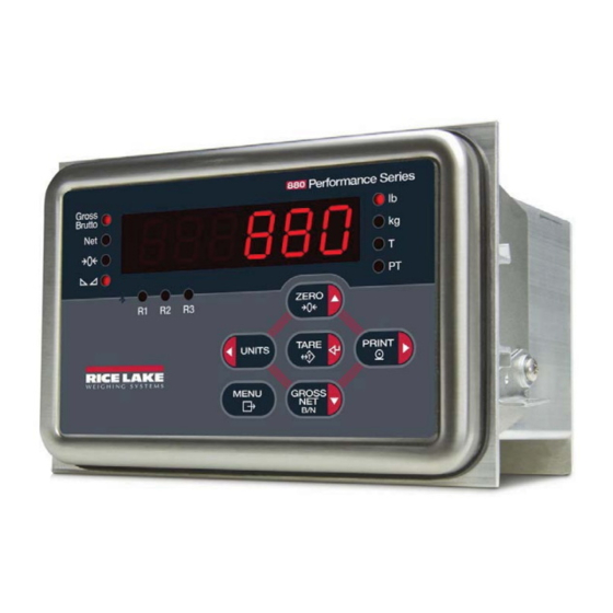
Operating Modes The three modes of operation for the 880 are described in the following sections. Weigh Mode In this mode, the indicator displays gross or net weights to indicate the type of weight value displayed and annunciators to indicate scale status. - Page 8 TARE PRINT UNITS MENU GROSS Figure 1-1. 880 Front Panel Display (Universal Model Shown) Function The Zero key sets the current gross weight to zero. ZERO Also used to navigate to different menus or to select another digit when editing a value.
- Page 9 Function The Clear key clears a numeric entry from the LCD. The Decimal Point key inserts a decimal point where necessary. The Numeric Keypad can be used to enter values. Values may also be entered by scrolling through values with the arrow keys. Table 1-1.
-
Page 10: Menu Structures And Parameter Descriptions
UNITS desired menu group appears on the display, then press to move down to the GROSS sub-menu or parameter to be edited. When moving through the menu parameters, the current selected value appears first on the display. 880 Operation Manual... -
Page 11: Editing Procedure For Numeric Values (880Plus Only)
Use the navigation keys to move the decimal point left or right. Press when done. TARE See the 880 Technical manual (PN 158387) for more information. Alphanumeric Entry Procedure Use the following scheme for alphanumeric entry when using the five button keypad. -
Page 12: Indicator Operations
When editing fractional numeric values, the decimal point must be positioned in accordance with the primary units formatting, otherwise the keyed number may be rejected by the software. Indicator Operations Basic 880 operations are summarized below. 1.6.1 Toggle Gross/Net Mode GROSS Press to toggle the display mode between gross and net. -
Page 13: Preset Tare (Keyed Tare)
1.6.6 Preset Tare (Keyed Tare) Tare mode must be set to keyed or both for the preset tare feature to function. TARE . 000000 1. With the scale empty and zero weight on the display, press will display with the focused digit flashing. 2. -
Page 14: Setpoints
Select the type by pressing to desired setting, then press to set the value. For complete list of choices see the 880 Technical manual (PN 158387) for more information. MENU When all settings have been made, press to return to weigh mode. - Page 15 Display or Edit Setpoint Value MENU 1. Press . Audit is displayed. until Setpts is displayed. 2. Press 3. Press and the first available setpoint number is displayed. 4. Press to toggle through each setpoint that is operator accessible. . Value is displayed. 5.
-
Page 16: Set Time And Date
5. While the accumulator value is displayed, press to print the value. The format of the print output can be configured using the accumulator print format. See the 880 Technical manual (PN 158387) for more information. 12 880 Operation Manual... -
Page 17: Clear The Accumulator
If there is not a tare in the system, the value displayed will be zero and the Gross and Net LED will be turned off. See the 880 Technical manual (PN 158387) for more information pertaining to the regulatory mode of operation. -
Page 18: Configuration
Configuration Methods The 880 indicator can be configured by using the front panel keys to navigate through a series of configuration menus or by sending commands or configuration data to the EDP port. Configuration using the menus is described in the 880 Technical manual (PN 158387). -
Page 19: Edp Command Configuration
2.1.2 EDP Command Configuration The EDP command set can be used to configure the 880 indicator using either a personal computer or terminal. Like Revolution, EDP command configuration sends commands to the indicator EDP port; unlike Revolution, EDP commands can be sent using any external device capable of sending ASCII characters over a serial connection. -
Page 20: Menu Structures And Parameter Descriptions
Menu Structures and Parameter Descriptions The following sections provide graphic representations of the 880 menu structures. In the actual menu structure, the settings you choose under each parameter are arranged horizontally. To save page space, menu choices are shown in vertical columns. The factory default setting appears at the top of each column and is bolded. -
Page 21: Scale Menu
2.2.3 Scale Menu ..SETUP ..SCALE SPLIT FORMAT ZTRKBN ZRANGE MOTBAN OVRLOA SSTIME DSPRAT GRADS 0-100 0-100 0-100 1-65536 1-80 FS+2% 10000 FS+ 1D 2RNG 1-100000 FS+ 9D 3RNG Figure 2-6 2INTVL 3INTVL SMPRAT DFSENS DFTHRH TAREFN PWRUPM ACCUM THRESH CALIBR... - Page 22 10000 weight weight weight 888880 888888 888888 8.88888 888880 888880 88.8888 8.88888 8.88888 888.888 88.8888 88.8888 8888.88 888.888 888.888 NONE 88888.8 8888.88 8888.88 If SPLIT = 2RNG, 3RNG, 2INTVL, or 3INTVL Figure 2-6. Format Menu Structure 18 880 Operation Manual...
- Page 23 Calibration Menu ..SETUP ..SCALE ..CALIBR WZERO WVAL WSPAN WLIN REZERO LAST TEMP Press Enter to Press Enter to recall Press Enter to Display and edit Previous A/D raw Previous A/D raw test weight value compensate for the last established temporarily zero the counts are shown.
-
Page 24: Feature Menu
-9999 bis +9999 Shown if LOCALE is ON ZERO GRSNET UNITS PRINT TARE UNLOCK UNLOCK UNLOCK UNLOCK UNLOCK LOCK LOCK LOCK LOCK LOCK MENU UNLOCK UNLOCK LOCK UNLOCK UNLOCK LOCK LOCK LOCK Figure 2-8. Feature Menu Structure 20 880 Operation Manual... - Page 25 Region Menu ..SETUP ..FEATUR REGION REGWOR DECFMT TIME DATE REGULA DFORMT D SEP NTEP GROSS CANADA BRUTTO COMMA MMDDY4 SLASH 000000 INDUST DDMMY4 DASH NONE Y4MMDD SEMI OIML Y4DDMM TFORMT T SEP MMDDY2 12 HOUR COLON XX.XXAM DDMMY2 See INDUST 24 HOUR...
-
Page 26: Ports Menu
..SETUP ..PORTS USBCOM ETHNET FLDBUS SWAP DVCNET PRFBUS Address Address NONE Figure 2-11 Figure 2-12 BYTE number number BOTH LOAD SAVE? ALL ? CFG ? CAL ? Figure 2-10. Ports Menu Structure 22 880 Operation Manual... - Page 27 Com and USBCOM Menu ..SETUP ..PORTS USBCOM TERMIN ECHO TRIGGE RESPNS EOLDLY PRNMSG SFMT 0-255 CR/LF format COMAND STRIND STRLFT Menu structure PROGIN if TRIGGE is set to STRIND or STRLFT. TRIGGE BAUD BITS STOP B TERMIN ECHO RESPNS...
-
Page 28: Ethernet Communications Menu
TIMOUT number number ALPHA/NUM number number CR/LF ECHO RESPNS ECHO RESPNS SFMT ALPHA/NUM Figure 2-12. Ethernet Communications Menu Structure 2.2.7 USB Host LOAD SAVE? ALL ? CFG ? CAL ? Figure 2-13. USB Host Menu Structure 24 880 Operation Manual... -
Page 29: Print Format Menu
2.2.8 Print Format Menu ..SETUP ..PFORMT GFMT NFMT ACCFMT SPFMT HDRFMT format PORT format USBCOM ETH-S ETH-C USBMEM Figure 2-14. Print Format Menu Structure See the 880 Technical Manual (158387) for port choice descriptions. Configuration 25... -
Page 30: Setpoint Menu
Same as SETPT1 See Figure 2-16 GROSS Menu Layout A -GROSS -NET %REL PAUSE See Figure 2-17 DELAY Menu Layout B WAITSS COUNTR See Figure 2-18 TIMER AUTJOG Menu Layout C CONCUR Figure 2-15. Setpoint Menu Structure 26 880 Operation Manual... - Page 31 Setpoint Menu – Layout A BRUTTO, NETTO, -BRUTTO, -NETTO, %REL VALUE TRIP BANDVAL HYSTER PREACT PREVAL number number number number HIGHER If PREACT LOWER is ON or LEARN If TRIP = If TRIP = LEARN INBAND INBAND HIGHER or OUTBAND or LOWER OUTBAN PREADJ...
- Page 32 Based on which DIGIO SLOT 0 INVERT are config as OUTPUT SLOT 1 SLOT1 – If RELAY option board is installed. SLOT 0 – If any DIGIO are configured as OUTPUT. Figure 2-18. Setpoint Menu Structure – Layout C 28 880 Operation Manual...
-
Page 33: Digital Input/Output Menu
2.2.10 Digital Input/Output Menu ..SETUP ..DIGIO SLOT 0 BIT 2-4 BIT 1 Same as SLOT 0 PRINT BIT 1 ZERO TARE UNITS DSPTAR BATRUN BATRST CLEAR NT/GRS BATSTR BATSTP DSPACC CLRCN BATPAS OUTPUT PROGIN Figure 2-19. Digital Input/Output Menu Structure 2.2.11 Analog Output Menu The ALGOUT menu is used only if the analog output option is installed. -
Page 34: Appendix
Appendix 3.1 Displayed Error Messages The 880 provides a number of front panel error messages to assist in problem diagnosis. Table 3-1 lists these messages and their meanings. Error Message Description Solution Over range Check for improper load cell ¯ ¯ ¯ ¯... -
Page 35: Specifications
3.2 Specifications Power Line Voltages Input Voltage – 100-240VAC, 9-36VDC Input Frequency – 47-63Hz Power Consumption AC: 15 watts DC: 20 watts Analog Specifications Full Scale Input Signal -45 mV to +45 mV Excitation Voltage 10 VDC ±, 8 x 350Ω or 16 x 700Ω load cells Sense Amplifier Differential amplifier with 4- and 6-wire sensing... - Page 36 File Number: E151461 Panel Mount Model File Number: E151461, Vol 2 The 880 DC indicator must be connected to a class 2 power source in accordance with the NEC (National Electrical Code) and local regulations. See equipment data plate for power requirements.
- Page 37 Notes Appendix 33...
- Page 38 Notes 34 880 Operation Manual...
- Page 40 Specifications subject to change without notice. Rice Lake Weighing Systems is an ISO 9001 registered company. 230 W. Coleman St. • Rice Lake, WI 54868 • USA U.S. 800-472-6703 • Canada/Mexico 800-321-6703 • International 715-234-9171 • Europe +31 (0)26 472 1319 www.ricelake.com...
Need help?
Do you have a question about the 880 and is the answer not in the manual?
Questions and answers