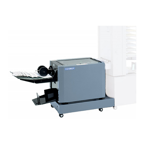
Duplo DBM-120 Installation Manual
Connecting kit
model: dc-6000s;dc-8000s 2;
dc-10000s
Hide thumbs
Also See for DBM-120:
- Instruction manual (47 pages) ,
- Maintenance manual (44 pages) ,
- Installation manual (12 pages)
Advertisement
Advertisement
Table of Contents

Subscribe to Our Youtube Channel
Summary of Contents for Duplo DBM-120
- Page 1 Duplo DBM-120 DC-6000S / 8000S 2 / 10000S Connecting Installation Manual Provided By http://www.MyBinding.com http://www.MyBindingBlog.com...
- Page 2 DBM-120 CONNECTING KIT (MODEL: DC-6000S/8000S 2/10000S) INSTALLATION MANUAL Specialized person only...
-
Page 3: Table Of Contents
Retain this Installation Manual for future reference as it will be needed for subsequent maintenance such as relocation. TABLE OF CONTENTS Standard Accessories ........1 Installing Procedure ........2 2-1. Releasing the DBM-120 Lock ....2 2-2. Checking the DBM-120 EPROM ..... 2 2-3. Setting the DBM-120 ....... 4 2-4. -
Page 4: Standard Accessories
1. STANDARD ACCESSORIES The following parts are enclosed in the connecting kit. Check that you have all of them before beginning installation. DBM-120 CONNECTING KIT (MODEL: DC-6000S/8000S 2/10000S) INSTALLATION MANUAL Specialized person only Name Qty. Name Qty. Communication cable Cable clamp Screw (MSKW4 ×... -
Page 5: Installing Procedure
2. INSTALLING PROCEDURE 2-1. Releasing the DBM-120 Lock Release the locks securing the bottom plate of the DBM-120 and movable unit DBM-120 together (2 each at the front and back). Fixing plate Loosen the two screws of the fixing plate, and move the fixing plate down and secure it. - Page 6 ROM version “11C-80033”. 11C8OO33 Check the EPROM version displayed in the display. If the version of the EPROM of the DBM-120 is 11C-80033 or more, it need not be replaced. If the version is 11C-80032 or less, replace the EPROM. NOTE : Be sure to replace the EPROM if the version is 11C-80032 or less, or the DBM-120 will not operate.
-
Page 7: Setting The Dbm-120
2. INSTALLING PROCEDURE 2-3. Setting the DBM-120 Enter the maintenance menu. q Press the (Escape) button once at the initial screen of the display on the control panel. w Turn the jog dial by three clicks towards the right to display “Number of Sheets”... - Page 8 Collator Suction NOTE : If the collator set at the control panel of the DBM-120 and the collator actually connected differ, the DBM-120 will not operate normally. To return to the initial screen Press twice the button.
-
Page 9: Checking The Suction Collator Eprom
DC-10000S → If the version is 96F-81999 or more, it need not be replaced. NOTE The DBM-120 will not operate normally with EPROMs of versions below the versions indicated above. Use the same EPROM versions for all towers connected. The EPROM is a service parts. -
Page 10: Collator
∗ This shows the DC-10000S. 2-6. Connecting the Suction Collator NOTE : Be sure to turn off the power of the DBM-120 and suction collator and disconnect the power plug from the outlet first before starting the work. Temporarily secure the connecting plate DBM-120 provided to the DBM-120 cabinet. - Page 11 Paper ejection rollers 8 to 12 mm (0.31" to 0.47") Adjust the height of the LU-HM exit so that DBM-120 the paper in-feed slot of the DBM-120 is 3 LU-HM to 7 mm (0.12" to 0.28") lower than the Guide LU-HM exit.
-
Page 12: Connecting The Communication Cable
2. INSTALLING PROCEDURE Turn on the power supply of the DBM-120, and set to the A3 size. Refer to “6-1. Basic Operation” in the instruction manual of the DBM-120 for details on setting the paper size. Adjust at the long holes of the connecting plate so that the A3 mark on the indication label of the DBM-120 faces the LU-HM exit jam sensor side facing up, and tighten the screws temporarily secured in step 2 to secure the connecting plate and LU-HM. - Page 13 Screw (MSKW4 × 8) t ........2 Connecting plate Cable clamps NOTE : Move the DBM-120 unit to and fro when changing the paper size. Move aside the power cord so that it does not touch the DBM-120 at this time. This ends the installation procedure.


Need help?
Do you have a question about the DBM-120 and is the answer not in the manual?
Questions and answers