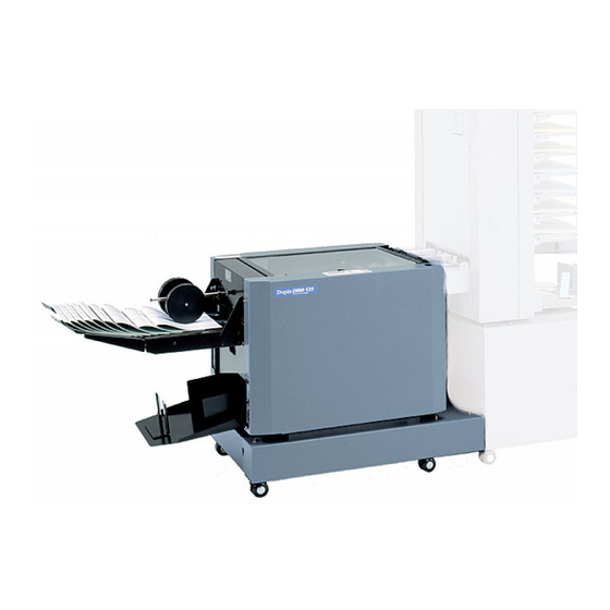
Duplo DBM-120 Maintenance Manual
Stapler folder
Hide thumbs
Also See for DBM-120:
- Instruction manual (47 pages) ,
- Installation manual (13 pages) ,
- Installation manual (12 pages)

Related Manuals for Duplo DBM-120


Summary of Contents for Duplo DBM-120
- Page 1 Duplo DBM-120 Stapler Folder Maintenance Manual Provided By http://www.MyBinding.com http://www.MyBindingBlog.com...
- Page 2 STAPLER FOLDER DBM-120 MAINTENANCE MANUAL...
-
Page 3: Table Of Contents
TABLE OF CONTENTS CHAPTER 1 MECHANISM 1. Outline of Each Mechanism and Adjustments ............ 1-2 2. Maintenance ........... 1-11 CHAPTER 2 ELECTRICAL COMPONENTS 1. Block Diagram of Structure and Outline of Each Block ............2-2 2. Errors and Causes .......... 2-10 3. - Page 4 CHAPTER 1 MECHANISM 1. Outline of Each Mechanism and Adjustments ............ 1-2 1-1. Conveyance Mechanism (Entrance) ..1-2 1-2. Back Jogger Mechanism ....... 1-2 1-3. Side Jogger Mechanism ......1-3 1-4. Stapler/Clincher Mechanism ....1-4 1-5. Folding Knife/Folding Roller Mechanism ..........1-8 1-6.
-
Page 5: Outline Of Each Mechanism And Adjustments
1. OUTLINE OF EACH MECHANISM AND ADJUSTMENTS 1-1. Conveyance Mechanism (Entrance) Paper is conveyed by the flat belt. Adjustments (1) Adjusting the tension of the timing belt Adjust the position of the pinch roller unit so that the belt slacks by 10 mm when a pressure of 1.96 N (200 gf) is applied. -
Page 6: Side Jogger Mechanism
1-3. Side Jogger Mechanism The timing belt moves forward and backward from the rotating movements of the stepping motor. The jog plate pushes in the paper. Adjustments (1) Fixing the STS belt and bracket With the bracket touches against the two sides, fix the plate and STS belt. Touch Touch 11C-1635X... -
Page 7: Stapler/Clincher Mechanism
1-4. Stapler/Clincher Mechanism The stapler unit staples the paper while the crank shaft makes one round by the DC motor, and at the same time, the cam drives the clincher to bend the staple flat. Adjustments (1) Adjusting the height of the clincher When the cam is at the top dead point, adjust so that the upper surface of the clinch plate and tip of the clincher are of the same level. - Page 8 (2) Adjusting the front and back positions of the stapler unit Adjust the position at which staples come out of the stapler unit to the groove of the clincher. q Set the stapler unit with the staple cartridge removed and clincher at the 140 (5" 1/2) position of the indication label.
- Page 9 (3) Adjusting the pushing amount of the stapler unit Set to the stapling position (bottom dead point) and check the pushing amount of the stapler unit by inserting the tool. q Remove the M3 screws, and remove the staple remaining detection sensor (upper side). Staple remaining detection sensor (Upper side) w Set the stapler unit with the staple cartridge removed and clincher at the 140 (5"...
- Page 10 (4) Adjusting the position of the stapler home 11C-2040X PH angle sensor When the rod is at the top dead point, adjust the PH angle to the position where it blocks the optical axis of the photointerrupter by 2 to 3 mm. Optical axis 11C-2036X (5) Adjusting the position of the stopper...
-
Page 11: Folding Knife/Folding Roller Mechanism
1-5. Folding Knife/Folding Roller Mechanism Adjustments (1) Adjusting the sliding part of the knife base 11C-3004X Knife Adjust the guide so that the knife base moves over 11C-3006X the sliding part smoothly without shaking. Knife base 92W-1047X Guide Screw Sliding part (2) Adjusting the height of the home sensor of the folding knife Touch the sensor bracket against the edge of the... -
Page 12: Folding Conveyance Mechanism
1-6. Folding Conveyance Mechanism The flat belts sandwich and convey the paper single-folded by the folding roller. Precautions on replacing the flat belt Replace taking note of the rotating direction of the flat belt. (Arrow at the back of the flat belt) Replace the flat belt in pairs. -
Page 13: Conveyance Mechanism (Exit)
1-8. Conveyance Mechanism (Exit) Paper is conveyed by the flat belt. Adjustments (1) Adjusting the standby position of the roller Adjust the angle of the angle so that the mylar and 98H-4347X roller become even. Roller 11C-6074X 952-1438X Mylar Angle (2) Adjusting the position of the solenoid With the roller touching the flat belt, adjust the 98H-4347X... -
Page 14: Maintenance
2. MAINTENANCE Clean the following parts Rubber roller Resin roller Flat belt Folding roller Index plate Photointerrupter Main unit Remote unit Switching power supply Oil the following parts (Equivalent to Nisseki Mitsubishi Co. Ld. FBK oil R028) Sintering bearing Link rotating fulcrum of the solenoid Grease the following parts (Equivalent to Dowconning Co. - Page 15 This page is a blank page.
- Page 16 CHAPTER 2 ELECTRICAL COMPONENTS 1. Block Diagram of Structure and Outline of 1-36. Saddle-stapling Paper Ejection Paper Each Block ............2-2 Switch ............ 2-8 1-1. MC Unit ..........2-5 1-37. Side-stapling Paper Ejection Paper 1-2. OP Unit (Control Panel) ......2-5 Switch ............
-
Page 17: Block Diagram Of Structure And Outline Of Each Block
1. BLOCK DIAGRAM OF STRUCTURE AND OUTLINE OF EACH BLOCK 1-2. OP unit (Control panel) 1-3. Staple motor 1-21. Side-stapling gate solenoid 1-4. Knife motor 1-22. Conveyance clutch 1-5. Folding conveyance motor 1-23. Total counter 1-6. Conveyance motor 1-24. Staple home sensor 1-7. - Page 18 1-23 1-14 1-34 1-31 1-21 1-24 1-32 1-19 1-18 1-12 1-33 1-10 1-11 1-42 1-40 1-30 1-43 1-22 1-44 1-41 11C-M12M0-0004-0...
- Page 19 1-16 1-15 1-27 1-36 1-28 1-26 1-25 1-29 1-37 1-13 1-35 1-17 11C-M12M0-0004-0...
-
Page 20: Mc Unit
1-1. MC Unit The MC unit controls the whole machine by the 8-bit microprocessor. It also incorporates a stepping motor, DC motor, and solenoid driving circuit. It has a built-in DC converter which generates +5 V with the DC +24 V power supply input. A DC +5 V power supply is used for ICs and sensors while a DC +24 V is used for driving the motor and solenoid. -
Page 21: Stopper Unit Motor
1-10. Stopper Unit Motor DC +24 V power supply stepping motor. Moves the stopper unit incorporating the stapling/folding stoppers. 1-11. Stopper Motor DC +24 V power supply stepping motor. Drives the stapling/folding stoppers. 1-12. Stopper Home Sensor Sensor for detecting the home positions of the stapling/folding stoppers. Uses a photointerrupter. 1-13. -
Page 22: Conveyance Clutch
1-22. Conveyance Clutch Electromagnetic clutch for transmitting the conveyance force to the stapling/folding stopper section. Uses a DC +24 V power. 1-23. Total Counter Electromagnetic counter. Uses a DC +24 V power. Counts up with each stapling/folding or folding operation. 1-24. -
Page 23: Stopper Unit Home Sensor
1-33. Stopper Unit Home Sensor Sensor for detecting the home position of the stopper unit. Uses a photointerrupter. 1-34. Side Jogger Home Sensor Sensor for detecting the home position of the side jogger. Uses a photointerrupter. 1-35. Staple Paper Switch Normal closed switch. -
Page 24: Main Power Switch
1-43. Main Power Switch Incorporated in the remote unit. Used to turn ON/OFF the power supply of the machine. 1-44. Power Supply Inlet Incorporated in the remote unit. Connected to the power cord. 1-45. Module Connector 1 Connector for communication with the machine connected. When performing communication from the upstream processing unit, insert an interface cable. -
Page 25: Errors And Causes
2. ERRORS AND CAUSES 2-1. When Paper Jams Occur The first line of the LCD on the control panel displays “Paper Jam”. The second line displays “In Paper Conveyer” (paper conveyer section), “In Stapler” (stapler section), or “In Folder” (folder section) according to where the paper has jammed. - Page 26 NOTE : The following causes may be suspected if jam codes are displayed even though no paper jam has actually occurred. The lever of the paper switch does not return There are paper bits or foreign objects jammed on the paper switch The paper switch is faulty The connection between the paper switch and MC unit is faulty The MC unit is faulty...
-
Page 27: Troubleshooting
2-2. Troubleshooting When a problem occurs, the first line of the message on the LCD of the control panel will display “Malfunction”. The second line will display the name of the problem. Details are provided below. Details of problems (1/2) Display in 2nd Line Description (First Half) - Page 28 Display in 2nd Line Description (First Half) (Second Half) Stapler Motor Home-Out Trouble The home sensor does not turn OFF (penetrating) within the specified time after the motor has turned ON. ------------------------------------------------------------------------------------------------------- Home-In Trouble The home sensor does not turn ON (blocking) within the specified time after the motor has turned ON.
- Page 29 Display in 2nd Line Description (First Half) (Second Half) ∗∗ Motor Home-In Trouble When the home sensor is OFF (penetrating), the motor turned ON for moving ∗∗ to the direction towards the home, but the ∗∗: Side Jog, home sensor does not turn ON (blocking) within the specified Back Jog, time.
- Page 30 Details of problems (2/2) Display in 2nd Line Description Motor MPU ∗ CRC Error Communication error between the stepping motor control microprocessor and main control microprocessor in the MC unit ∗: 1, 2, 3 ------------------------------------------------------------------------------------------- <Cause> Malfunction of the MC unit Motor MPU ∗...
-
Page 31: Other Condition Messages
2-3. Other Condition Messages The control panel also displays messages of other conditions of the machine such as when a door is opened, etc. The causes of such messages are shown below. In some cases, if the message and actual condition differ such as when “Top Cover Open”... -
Page 32: Maintenance Mode
3. MAINTENANCE MODE Display Stop button Start button Power ON indicator Lights up when the stapler folder is turned ON. Clear Escape button button Jog dial/Enter button Function button 3-1. Entering the Maintenance Mode Press the escape button once on the initial screen of the control panel. Turn the jog dial by three clicks towards the right, “Number of Sheets”... -
Page 33: Sensor Check Mode
3-4. Sensor Check Mode When the sensor check mode is selected from the maintenance menu, “Sensor Check” will be displayed. Turn the jog dial to display the name of the sensor to be checked. The name can be checked as shown in the following examples. (Example 1) To check the back jogger paper sensor Pushing down the switch lever sets the display to “on”. -
Page 34: Precautions On Replacing The Mc Unit
4. PRECAUTIONS ON REPLACING THE MC UNIT Fine adjustment data and customized sizes are registered in the EEPROM (nonvolatile memory) on the MC unit (board). Therefore previous data will be lost when the MC unit is replaced. Note down the fine adjustment data and customized sizes prior to replacement and input them after replacement. -
Page 35: Precautions On Replacing Fuses
5. PRECAUTIONS ON REPLACING FUSES CAUTION : For continued protection against risk of fire, replace only with same type and rating of fuse. Fuse type and rating: UL, IEC127 Fuse T 6.3 A Board display: FUSE 1 2-20 11C-M12M0-0004-0... -
Page 36: Lcd Map
6. LCD MAP 6-1. LCD Map (Normal Menu) NOTE Turning the jog dial switches the display within the same hierarchy. Pressing it enters the hierarchy below. If no hierarchy exists below, turning the jog dial selects an item or sets a value. Pressing it confirms the selected item or value set. - Page 37 Custom 2 Size L= 364 W= 257 Length L= 364 Select Length L= 364 ∗ Width W= 257 Select Width W= 257 ∗ Custom 3 Size L= 364 W= 257 Length L= 364 Select Length L= 364 ∗ Width W= 257 Select Width W= 257 ∗...
- Page 38 Other Setting Staple Sensor Stpl. Sen. on/off on off ∗ Tone Tone on/off on off ∗ LCD Setting Shift Speed Normal Select Shift Sp. Fast Normal Slow Very Slow ∗ Blink Speed Normal Select Blink Sp. Fast Normal Slow Very Slow ∗ mm/In Setting Meter Select mm/In...
-
Page 39: Lcd Map (Maintenance Mode)
6-2. LCD Map (Maintenance Mode) NOTE : In the sensor check mode, the sensor state will be displayed as “on” or “off”. Maintenance Menu (Initial screen) Select M. Mode ROM Version MC ROM Version xxx-nnnnn SPM ROM Version xxx-nnnnn OP ROM Version xxx-nnnnn IF ROM Version xxx-nnnnn... - Page 40 Sensor Check Stp. Gate Hm on Sensor Check M. Move Hm on Sensor Check M. Move Index on Sensor Check Staple Hm on Sensor Check Staple Index on Sensor Check Knife Hm on Sensor Check Knife Index on Sensor Check Feed Index on Sensor Check F.
- Page 41 Motor Test Stp. Gate Mot. Solenoid Test Fold Colo Sol. Solenoid Test NOTE) Displayed but no operations performed. Staple Colo Sol. Solenoid Test NOTE) Displayed but no operations performed. P. In Sol. Language Japanese Select Language Japanese English Select Paper Ref Side Select Paper Ref Center Side...
-
Page 42: Overall Schematic Diagram
7. OVERALL SCHEMATIC DIAGRAM OP UNIT SWITCHING POWER SUPPLY RM UNIT 99J-8015 11C-8021 11C-8013 MC UNIT 204 PURPLE PURPLE REM SW-A 11C-8007 BLUE 201 WHITE 205 BLACK REMOTE POWER SWITCH GRAY 001 BROWN AC (N) AC (L) REM SW-C 054-10258 BLUE 002 BROWN 202 BLACK... -
Page 43: Wiring Diagram
8. WIRING DIAGRAM Details of D Details of A Brass screw M4 with SW 3303 Motor bracket Details of bottom plate section Details of I 11C-4030 OCB-1000 BJU bundled wire unit Switch Bundled wire unit 5 054-10259 11C-8305 11C-8311 3305 SKB-1M Motor Angle F... - Page 44 11C-M12M0...
Need help?
Do you have a question about the DBM-120 and is the answer not in the manual?
Questions and answers